Scalable voip mobility intedration and deployment- P27 pdf
Bạn đang xem bản rút gọn của tài liệu. Xem và tải ngay bản đầy đủ của tài liệu tại đây (275.37 KB, 10 trang )
260 Chapter 6
www.newnespress.com
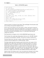
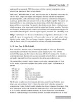
RADIUS Server
WLAN Controller
Access Points
Mobility Domain
Master Key (MSK)
Master Key (MSK)
PMK-R0
PMK-R1
PTK
PMK-R1
PMK-R0 is derived here, but not transmitted
PTK
R0 Key Holder
R1 Key Holder
PTK Holder
a) With a wireless controller architecture, locating where the 802.11r key holders can be rather simple. The mapping is, in fact, almost the same as for WPA2, with
the PTK (connection key) holder being the access point, and the PMK holders all being in the controller. On a handoff to a new access point, that access point only
needs to request a new PTK from the controller, which will produce a new PMK-R1 along the way, using the original PMK-R0. The main thing to remember is that there
is only one PMK-R0 for the entire mobility domain.
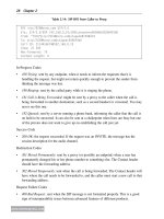
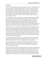
RADIUS Server
Access Points
Mobility Domain
Master Key (MSK)
Master Key (MSK)
PMK-R0
PMK-R1
PTK
PMK-R1
PMK-R0 is derived here,
but not transmitted
PTK
R0 Key Holder
R1 Key Holder
PTK Holder
a) With a standalone access point architecture, the mapping is quite different. There is no centralized PMK-R0 holder. Instead, the first access point that the client
performs 802.1X becomes the R0 Key Holder. When the client moves to another access point, the new access point needs to discover which original access point
is the R0 Key Holder, and then request a PMK-R1 from it. The new access point will then generate the PTKs as needed, from its local store. In this way, each access
point still has a PMK and a PTK, just as with WPA2, but there may be a higher-order PMK holder elsewhere in the network if the cliient has handed off.
Figure 6.8: Ways of Embedding 802.11r in Wi-Fi
Voice Mobility over Wi-Fi 261
www.newnespress.com
802.11k has many potential uses beyond voice, but because voice network depend on the
efficient functioning of the underlying technology, it is worth looking into 802.11k here.
The reader is warned, however, that the material here can become a little dense, and you
may wish to skip around to get a better sense of how all of these new capabilities fit
together.
6.2.6.1 The Capabilities of 802.11k
802.11k contains a long list of features, as it is more a framework and a collection of
independent uses of that framework than it is a solution to one specific problem. Many of
these features come with variants, based on the willingness of vendors to implement the
features. The way that the access point and client can determine which subset of 802.11k
the devices may support is through the exchange of an RRM Extended Capability
information element.
Table 6.11 gives the complete list of capabilities that can be expressed. This extensive list is
overwhelming, belying the fact that 802.11k is made of multiple methods of performing
roughly the same thing. That does not meant that there is no usefulness within the standard,
but rather that interoperability among vendors is more important than ever. The following
sections will expand on the features more likely to apply to a voice mobility network with
Wi-Fi as one of the legs.
6.2.6.2 Requests and Reports
Not every capability within 802.11k is a request and report, but most of it is. The idea of
the request and report structure came originally from 802.11h, which is the amendment
concerning performing radar detection for DFS bands, first in Europe and now applicable to
the United States and Canada as well. In the context of DFS, the goal is to request or
require stations to scan in order to determine the presence of radar. 802.11k has broadened
out the purpose of the mechanism, allowing for a broad number of properties to be
measured and reported.
A request for measurement is generally requested for in a Radio Measurement Action frame,
generically described in Table 6.12. The dialog token specifies which of the possibly
multiple outstanding requests a response matches up to, and is specified by the requester
and copied by the responder. The number of repetitions specifies how many times the report
is to be produced from new information and sent to the responder, with a value of 65,535
(all bits set) specifying to continue forever, until explicitly cancelled.
The contents of each Measurement Report element are given in Table 6.13. The
measurement token is a unique number of this specific measurement, to identify it if
multiple measurements are processing in the background. (They serve a different purpose
from the dialog tokens, and the two numbers are not related.) The measurement request
262 Chapter 6
www.newnespress.com
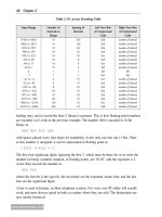
Table 6.11: The 802.11k RRM extended capability information element
Link
Measurement
Neighbor
Report
Parallel
Measurements
Repeated
Measurements
Beacon
Passive
Beacon
Active
Beacon
Table
Beacon
Reporting
Conditions
…
Bit: 0 1 2 3 4 5 6 7
…
Frame
Measurement
Channel
Load
Noise
Histogram
Statistics
Measurement
LCI
Measurement
LCI
Azimuth
Transmit
Stream
Triggered
Transmit
Stream
…
Bit: 8 9 10 11 12 13 14 15
…
AP
Channel
RRM
MIB
Operating Channel
Max Measurement
Duration
Non-operating
Channel Max
Measurement
Duration
Measurement
Pilot
Measurement
Pilot
Information
Neighbor
Report TSF
Offset
RCPI
…
Bit: 16 17 18–20 21–23 24–26 27 28 29
…
RSNI BSS Average Access Delay BSS Available Admission
Capacity
Antenna Information Reserved
Bit: 30 31 32 33 34–39
Voice Mobility over Wi-Fi 263
www.newnespress.com
Table 6.12: 802.11k Radio measurement request action frame
Category Action Dialog Token Number of
Repetitions
Measurement
Request Element
1 byte 1 byte 1 byte 2 bytes
n different copies
Table 6.13: Measurement request element format
Element ID Length Measurement
Token
Measurement
Request Mode
Measurement
Type
Measurement
Request
1 byte 1 byte 1 byte 1 byte 1 byte
variable
Table 6.14: 802.11k Radio measurement report action frame
Category Action Dialog Token Measurement
Report Element
1 byte 1 byte 1 byte
n different copies
mode specifies how the measurement is to be made. The Parallel bit (bit 0) states that this
measurement is to run in parallel with the next measurement request within the same frame.
The Enable bit (bit 1), Request bit (bit 2), and Report bit (bit 3) are used in concert to
determine whether the sender is requesting a new background (or autonomous) report series
to begin or end with this request, or whether the request is to run right away. The Duration
Mandatory bit (bit 4) specifies that the measurement is to run for exactly a certain amount
of time, specified later in the Measurement Request itself.
The notion of autonomous or background reporting exists to allow the requester to have the
other device send reports as needed. A further refinement allows the requester to specify
specific triggers, which the receiver uses to determine just when to send the autonomous
reports. In this way, the request protocol can be used to set up some sort of background
reporting agreement. How each report works is specified with the reports.
The response to a request comes in the format shown in Table 6.14, with the contained
Measurement Report shown in Table 6.15. The measurement report mode specifies the type
of report, and can be value 2 to indicate that the reporter is incapable of generating this sort
of report, or the value 4 to indicate that the reporter refuses to generate this sort of report,
probably given an unspecified decision that the reporting work is too burdensome for the
client at the time.
One can see that there is a large number of moving parts to this apparatus. The use for this
complexity will hopefully become clearer as we progress.
264 Chapter 6
www.newnespress.com
6.2.6.3 Beacon Reports
The first useful mechanism for 802.11k, especially as it applies to voice, is the beacon
report. The beacon report is a report from the client, to the access point, about the entries
within its scanning table. From the discussion on scanning in Section 6.2.2, one can imagine
that learning about the contents of the scanning table can have some positive specific uses.
The beacon report request comes in three variants: active reporting, passive reporting, and
beacon table reporting. These map directly to the scanning types: an active report is one in
which the client was demanded to perform an active scan first; a passive report is one
in which the client was demanded to perform a passive scan first; and a beacon table
report is where the client is only required to give what it currently has in its scanning table,
no matter how stale.
Table 6.16: Beacon request format
Regulatory
Class
Channel Randomization
Interval
Measurement
Duration
Measurement
Mode
BSSID SSID Reporting
Detail
AP
Channel
Report
1 byte 1 byte 2 bytes 2 bytes 1 byte 6 bytes
(optional) (optional) (optional)
Table 6.15: Measurement report element format
Element ID Length Measurement
Token
Measurement
Report Mode
Measurement
Type
Measurement
Report
1 byte 1 byte 1 byte 1 byte 1 byte
variable
Table 6.16 specifies the contents of the beacon request. The regulatory class and channel
together specify which channel the client is to scan or report on. (Regulatory class is needed
with the channel, because some channel numbers are reused in different bands.) The value
of zero for the channel means to report on all channels in the band; the value of 255 means
to report on all channels listed in the AP Channel Report. The randomization interval and
measurement duration are used to specify whether the report should start now or after a
delay, and how long the scan should take. The measurement mode specifies whether the
request is for a passive scan (0), active scan (1), or beacon table (2). The BSSID is used to
limit the request to produce the entry for just the given BSSID; this restriction is ignored if
the BSSID given is all zeros. Furthermore, the optional SSID limits the scanning for SSIDs
that match only, thus allowing the requesting access point to ignore other SSIDs. Finally,
the requester can specify just what it gets back about each entry. The entry is not returned
as arbitrary information; rather, a subset of the fields in each access point’s beacon or probe
response frame is returned, based on the contents of the reporting detail. The reporting
Voice Mobility over Wi-Fi 265
www.newnespress.com
detail can be for nothing extra (0), or for requested parts of the beacon, using an added IE
that appears at the end of the request and would be inappropriate to go into that level of
detail here. (A good wireless protocol analyzer will be able to satisfy any curiosity you may
have, if a device is using this protocol.)
The client that receives a request may choose to perform the request, or reject it for being
too busy. If the client accepts the request, it must perform the actions and report on them.
Now, there is no requirement that the client modify its real scanning table, the one it uses to
make handoff decisions on, or that it report back the contents of that table to the access
point. It is allowed to keep a separate table just for the purposes of 802.11k. However, the
hope behind the amendment is that the scanning and beacon table processes are related.
Table 6.17: Beacon response format
Regulatory
Class
Channel Measurement
Start Time
Measurement
Duration
Reported
Frame
Information
RCPI RSNI
…
1 byte 1 byte 8 bytes 2 bytes 1 byte 1 byte 1 byte
…
BSSID Antenna ID Parent TSF Frame Body
6 bytes 1 byte 4 byes
variable
Table 6.17 shows the structure of the report. Each report provides information on exactly
one BSSID. A Beacon Report fr-ame, a type of Management Report frame, will have
multiple Management Report information elements, with one element containing one
beacon report, to allow for reports to be sent back on multiple access points. The channel
specifies what channel the access point was on. The measurement start time specifies when
this measurement began, and the duration reports how long the measurement took. The
reported frame information is set to zero. The RCPI provides a measure of the signal
strength of the access point; the RSNI provides the signal-to-noise ratio for the same frame.
The BSSID field contains the BSSID of the access point. The antenna ID field specifies
which antenna the receiver heard the access point on, and is not terribly useful. The parent
TSF field specifies the lowest four bytes of the timestamp clock on the client when it
precisely heard the beginning of the beacon. Finally, the frame body contains all of the
requested and fixed field bits of the access point.
Considering the tremendous size of the requests and responses, especially when there
is a high amount of density in the environment, one might wonder what the purpose of
such a beacon report really is. The goal is to allow the access point to assign idle clients
266 Chapter 6
www.newnespress.com
with the task of informing it what its neighboring access points are, for use in the neighbor
report.
6.2.6.4 Neighbor Reports
The neighbor report is requested for by a client from the access point, and specifies a list of
neighboring access points. A client would request a neighbor report in order to supplement
its scanning list, most likely to avoid having to stay off channel for a potentially long period
of time. The information in the neighbor report comes from no particular source, however,
and clients are not expected to replace their scanning table with the limited information
returned in the neighbor report, or even to augment it in any significant way.
Together with the beacon report mechanism, however, one can picture an architecture where
clients do request neighbor reports to learn about off-channel access points, and where
access points do assign idle clients with the task of keeping them up to date.
Table 6.18 specifies the Neighbor Report Request Action frame. This frame is substantially
simpler than the one used for beacon requests, because the client is not allowed to change
the access point’s behavior or to require it to do work. Instead, the client can simply ask for
a neighbor report list, and can specify an optional SSID to limit the results down to the
given SSID, rather than see results for every SSID.
Table 6.19: 802.11k Neighbor report response action frame
Category Action Dialog Token Neighbor Report
Elements
1 byte 1 byte 1 byte
multiple
Table 6.18: 802.11k Neighbor report request action frame
Category Action Dialog Token SSID
1 byte 1 byte 1 byte
(optional)
The format of the neighbor report element is shown in Table 6.20. The BSSID is that of the
access point. The BSS Info field provides information as to whether the neighbor supports
the same security as the current access point, can participate in opportunistic key caching
(Section 6.2.4) with this access point, or supports a subset of 802.11 capabilities. The
channel and radio type of the neighbor is reported. Additionally, if the access point knows
the timestamp clock of the neighbor, the country of the neighbor, the RRM capabilities of
The access point will respond right away with a Neighbor Report Response Action frame,
as shown in Table 6.19. This response includes a number of Neighbor Report elements,
each element corresponding to one neighbor.
Voice Mobility over Wi-Fi 267
www.newnespress.com
the neighbor, or how many other BSSIDs the neighbor supports, these can be communicated
in the last four optional information subelements.
Table 6.20: Neighbor report element
Element
ID
Length BSSID BSS
Info
Regulatory
Class
Channel PHY
Type
TSF Country RRM
Capabi-
lities
Multiple
BSSID
1 byte 1 byte 6 bytes 4 bytes 1 byte 1 byte 1 byte
(opt.) (opt.) (opt.) (optional)
Table 6.21: Link measurement request frame
Category Action Dialog Token Transmit
Power Used
Maximum
Power
1 byte 1 byte 1 byte 1 byte 1 byte
Again, this is a somewhat involved protocol, and the meaning of most of what you see here
will not necessarily become required knowledge, as a good protocol analyzer will shed light
on what the protocol is communicating. But the intent is clear: the neighbor report is
designed to provide a way for the client to find a neighbor that it could very well hand off
to, without itself having to scan. In a perfect world, this can reduce scanning times, and it
still remains to be seen whether 802.11k will be successful in reducing times. Unfortunately,
some part of the process cannot be eliminated—DFS bands, for example, always require a
passive scan of the channel, whether the client is told about the access point’s presence on
that channel or not. However, more information can be better than less, and the neighbor
report mechanism aims to provide it.
Now, we can see that the neighbor report can be filled in from information gotten by a
beacon report.
6.2.6.5 Link Measurement and Power Reporting
It is not possible for a client or access point to guess what power the other is using.
Especially for systems that engage in dynamic transmit power control (see Section 6.1.3), if
the client or access point wants to make a decision on the basis of the power level at which
the other device is transmitting, it needs to find this information out explicitly.
To accomplish this, 802.11k provides for a method for requesting a link measurement. A
link measurement is an exchange where the requester tells the power level it is sending at,
and the reporter returns with what power level and SNR it saw that frame received at, thus
letting the requester know its link margin to the other device. Table 6.21 shows the contents
of the Link Measurement Request frame.
268 Chapter 6
www.newnespress.com
The responder puts together an immediate response formatted as specified in Table 6.22.
The TCP Report element, given in Table 6.23, specifies the power that the responder is
sending at. Its transmit power field is that of the link measurement response, and the link
margin field is the expected link margin as measured in a possibly proprietary way by the
responder. The receive and transmit antenna IDs are to help determine which antenna is
being used in complex, sectorized solutions. The RCPI reports the signal strength of the
originalLinkMeasurementrequestattheresponder,andtheRSNIreportsthesignal-to-
noise ratio.
Table 6.24: Traffic stream request
Randomization
Interval
Measurement
Duration
Peer Address Traffic ID Bin 0 Range Triggered
Reporting
2 bytes 2 bytes 6 bytes 1 byte 1 byte
(optional)
Table 6.22: Link measurement response frame
Category Action Dialog
Token
TPC
Report
Element
Receive
Antenna
ID
Transmit
Antenna
ID
RCPI RSNI
1 byte 1 byte 1 byte 1 byte 1 byte 1 byte 1 byte 1 byte
Table 6.23: TPC report element
Element ID Length Transmit Power Link Margin
1 byte 1 byte 1 byte 1 byte
With this much information available, no device lack knowledge of the transmit power or
link margin of the other.
6.2.6.6 Traffic Stream Metrics
802.11k also allows for one device to ask the other about the quality of the admission
control flows that it has. This is useful for inferring the voice quality of the link, and thus
allowing either side to take action to improve performance if something is going wrong.
Table 6.24 shows the information that is placed in the measurement request for these
metrics. The peer address is the address of the device whose performance wishes to be
measured. The traffic ID is the TID of the admitted stream that the requester would like to
find out about. The Bin 0 Range field is used to specify the properties of the histogram that
is returned. Finally, if a triggered reporting element is given, the requester can specify that
Voice Mobility over Wi-Fi 269
www.newnespress.com
the reporter send a report whenever conditions cross certain thresholds. The sorts of
thresholds which can be used include reporting because of excessive average errors (lost
packets), and consecutive errors.
…
Discarded
Frame
Count
Failed
Frame
Count
Multiple
Retry
Count
CF Polls
Lost
Count
Average
Queue
Delay
Average
Transmit
Delay
…
4 bytes 4 bytes 4 bytes 4 bytes 4 bytes 4 bytes
…
Bin 0 Range Bin 0 Bin 1 Bin 2 Bin 3 Bin 4 Bin 5
1 byte 4 bytes 4 bytes 4 bytes 4 bytes 4 bytes 4 bytes
The report format is given in Table 6.25. This report includes both exact counts and a
histogram of the nature of the errors. The transmitted frame count specifies the number of
frames sent successfully for the flow. The discarded frame count specifies the number of
frames that could not be delivered and were thrown away without any retransmissions
having been knowingly delivered. The failed frame count specifies how many frames were
lost, just like the discarded count, but excluding frames that timed out because they were in
a buffer for too long. The multiple retry count specifies the number of frames that took
more than one try to be successfully delivered. The CF Polls lost field can be ignored, as
CF Polling belongs to a part of the standard not used in WMM. The average queue delay is
the amount of time packets tend to be delayed until they start transmitting on the air. The
average transmit delay is the amount of time packets tend to be delayed until they are
successfully completed, including retransmissions. The histogram measures delay, and is
divided up into five bins, where each bin measures a range of values double that of the
previous bin, starting at Bin 1. The Bin 0 Range specifies the amount of time the delay
value for Bin 0 covers. For example, if Bin 0 Range is equal to 10, then Bin 0 covers
delays from 0 to 10.24ms. That would make Bin 1 cover the range from 10.24ms to
20.48ms, and Bin 2 would cover the range from 20.48ms to 40.96ms, and so on.
With this information, each side can measure the loss rates of the other, as well as the delay
profile.
6.2.6.7 Other Features of 802.11k
802.11k includes a plethora of other features, many of which are not likely to be as useful
for voice mobility deployments.
802.11k includes a provision for reporting on the noise levels that a client sees. It also
includes a provision for reporting on the activity of each device in the air, based on frame
counts. A peculiar mechanism known as measurement pilot frames exist, which serve as
frequent, miniature versions of beacons. This could have been useful for aiding in the