Scalable voip mobility intedration and deployment- P26 potx
Bạn đang xem bản rút gọn của tài liệu. Xem và tải ngay bản đầy đủ của tài liệu tại đây (170.91 KB, 10 trang )
250 Chapter 6
www.newnespress.com
3. At this point, if the new access point is on a different channel, the client will change
the channel of its receiver.
4. If the new channel is a DFS channel, the client is required to wait until it receives a
beacon frame from the access point, unless it has recently heard one as a part of a
passive scanning procedure.
5. The client will send an Authentication message to the new access point, establishing
the beginnings of a relationship with this new access point, but not yet enabling
data services.
6. The access point will respond with its own Authentication message, accepting the
client. A rejection can occur if load balancing is enabled, and the access point
decides that it is oversubscribed, or if key state tables in the access point are full.
7. The client will send a Reassociation Request message to the access point, requesting
data services.
8. The access point will send a Reassociation Response message to the access point. If
the message has a status code for success, the client is now associated with and
connected to this access point, and only this access point. Controller-based wireless
architectures will usually ensure this by immediately destroying any connection that
may have been left over if step 2 has not been performed. The access point may
reject the association if it is oversubscribed, or if the additional services the client
requests (mostly security or quality-of-service) in the Reassociation Request will not
be supported.
At this point, the client is associated and data services are available. Usually, the access
point or controller behind it will send a broadcast frame, spoofed to appear as if it were sent
by the client, to the connected Ethernet switch, informing it of the client’s presence on that
particular link and not on any one that may have been used previously.
If no security is employed, skip ahead to the admission control mechanisms, towards the
endofthelist.IfPSKsecurityisemployed,skipaheadtothefour-wayhandshake.
Otherwise, if 802.1X and RADIUS authentication is employed (WPA/WPA2 Enterprise),
we’ll continue immediately next. For any security mechanisms, you may wish to flip to
Section 5.6 for more details on the mechanisms.
9. The access point and client can only exchange EAP messages at this point. The
client may solicit the EAP exchange with an optional EAP Start message.
10. The access point will request the client to log in with an EAP Request Identity
message.
11. Depending on the EAP method required by the RADIUS server on the network, the
clientandaccesspointwillcontinuetoexchangeanumberofdataframes,allEAPOL.
Voice Mobility over Wi-Fi 251
www.newnespress.com
12. The access point relays the RADIUS server’s EAP Success or EAP Failure message.
If this is a failure, the access point will also likely send a Deauthentication or
Disassociation message to the client, to kick it off of the access point.
Atthispoint,theclientandaccesspointhaveagreedonthepairwisemasterkey(PMK),
based on the key material generated during the RADIUS exchange and sent to the access
point when the authentication process concluded. But, as Section 5.6.1.2 showed, the access
pointandclientstillneedtogenerateaper-connection,pairwisetransientkey(PTK),which
willbeusedtodotheactualencryption.Pre-sharedkey(PSK)networksskippedthelisted
EAPexchanges,andusethePSKasthemasterkey.
13. The access point send the first message in the RSN (802.11i) four-way handshake.
ThisisanEAPOLKeyframe.
14. The client sends the second message in the four-way handshake.
15. The access point sends the third message in the four-way handshake.
16. The client sends the fourth message in the four-way handshake.
At this point, all data services are enabled, and the client and access point can exchange
data frames. However, if a call is in progress, and WMM Admission Control is enabled,
the client is required to request the voice resources before it can send or receive a single
voice packet with priority. Until this point, both sides may either buffer the packets or send
the voice packets as best-effort. Section 6.1.1.2 has the details on WMM Admission
Control.
17. The client sends the access point an ADDTS Request Action frame, with a TSPEC
that specifies the over-the-air resources that both the upstream and downstream part
of the voice call will occupy.
18. The access point weighs whether it has enough resources to accept or deny the
request. It sends an ADDTS Response Action frame with the results.
19. If the request was successful, the client and access point will be sending voice
traffic and the call successfully handed off. On the other hand, if the request fails,
the client will disconnect from the access point with a Disassociation message,
because, although it is allowed to remain on the access point, it can’t send or
receive any voice traffic.
Hopefully, everything went well and the handoff completed. On the other hand, if any of
the processes failed, the connection is broken. The old connection was abandoned early
on—in step 8 for sure and step 2 for more charitable clients. In order to not drop the phone
call, the phone will need to restart the process from the beginning with another access
point—perhaps the original access point it just left, if none is available.
252 Chapter 6
www.newnespress.com
You will notice that the client has a lot of work to do to make the handoff successful, and
there are many places where the procedure can go wrong. Even if every request were to be
accepted, any loss of some of the messages can cause long timeouts, often up to a second,
as each side waits to make sure that no messages are passing each other by.
If nothing at all is done to optimize this transition, the handoff mechanics can take an
additional second or two, on top of the second or so taken by the scanning process before
the handoff decision was made. In the worst case, the 802.1X communication can take a
number of seconds.
Part of the issue is that the mechanisms are nearly the same for a handoff as they are for
when the client initially connects. This lack of memory within the network within basic
Wi-Fi prevents any optimizations and requires a fresh start each time.
6.2.4 Reducing Security Handoff Overhead with Opportunistic Key Caching
The good news is that the 802.1X mechanisms can be taken out of the picture for handoffs,
for wireless architectures with a controller (or large number of radios in one access point).
This mechanism, available today for many vendors, is known as opportunistic key caching
(OKC).Thenamecomesfromthemainconceptunderlyingthetechnology.Onceaclient
performstheauthenticationwiththeRADIUSserver,andhasaPMK,thereisnoreasonfor
ittohavetonegotiateanewonejusttohandoffandcreateanewPTKjustforthataccess
point.Theterm“opportunistic”isusedbecausethemechanismwasdesignedtobeasimple
extensionof802.11i,andtheclientisnotmadeawarethatOKCisenabled.Ifitworks,it
works. If not, no problems arise except the increased time required for doing the handshake.
ThemainprotocolforOKCisidenticaltotheordinarykeycachingmentionedinSection
5.6.2.3. The only difference is that whereas ordinary key caching requires that the client is
returning to an access point where it had already performed 802.1X, opportunistic key
cachingrequiresonlythatthenewaccesspointsomehowhaveaccesstothePMK,even
though it was created on a different access point.
Howcanthiswork?ThePMK,ifyourecall,doesnothaveanyinformationuniquetothe
wireless network within it. It is a function purely of the EAP protocol in use between the
wireline RADIUS server and the wireless client. There is no intrinsic reason that the same
PMKcannotbeusedfordifferentaccesspoints,aslongasthefollowingtworestrictions
areheldto:thePMKmustneverbetransmittedasplaintextorusingweakencryption,and
thePMKmustnothaveexpired.
Inpractice,opportunistickeycachingimplementationsnevermovearoundthePMK.
Instead, these implementations take advantage of the architecture of the WPA2 protocol and
how it interacts with 802.1X. 802.1X doesn’t know about clients and access points. Instead,
it uses a different language, in which the role of the user is held by a supplicant, and the
Voice Mobility over Wi-Fi 253
www.newnespress.com
role of the network is held by an authenticator. These terms and roles were described in
Section 5.6.2, when 802.1X was introduced. The mapping of the supplicant to real devices
is clear: the supplicant is a part of the client. The authenticator, on the other hand, has
flexibility built in. For standalone access point architectures, the authenticator is a part of
the access point. For controller-based architectures, however, the authenticator is almost
always in the controller.
Nowwegetasenseforthescaleofopportunistickeycaching.ThePMKwasoriginally
created in the authenticator, and most opportunistic key caching architectures leave the
PMKinsidetheauthenticator,nevertocomeout.Forcontroller-basedarchitectures,the
controllergeneratesthePTKwithintheauthenticator,andthendistributesittothe
encryption engine, which may be located locally in the controller or in the access points.
Withopportunistickeycaching,then,theonlychangeistoallowaclientwithaPMKto
associatetoanewaccesspoint,andtousethePMKforthenewconnectionasifithad
been negotiated on that access point.
There is no addition of protocols or state changes in opportunistic key caching, which
explains why it is so prevalent within network implementations. The only changes are to
clients,whohavetocreateanewPMKID,basedontheoriginalPMK,whentheyassociate
toanewaccesspoint,andtotheauthenticator,whichneedstolookpastthataPMKIDwas
notcreatedforthePMK,createthenewone,andthencontinueasifnothingunusualhad
happened.
You should look for wireless clients and network infrastructure that supports opportunistic
keycachingwhenrollingoutavoicemobilitynetwork.OKChasbeengenerallyembraced
by the industry, though there are a few notable exceptions, and is generally used as the
solution to the 802.1X overhead.
6.2.5 An Alternative Handoff Optimization: 802.11r
As good as opportunistic key caching sounds, it does have its flaws. The major flaw is that
the client has no way of knowing whether a new access point it is associating to has the
PMKalready.Thisisnotamajoraw,inthattheopportunisticnatureofthekeycaching
doesn’t require the client to make the correct guess. However, in areas where access points
from multiple authenticators overlap, such as at the border area between two controllers’
domains, it is possible for the client to be unable to take advantage of the optimizations.
For this reason, as well as some detailed interest in having a key caching mechanism that is
specified in the 802.11 standard—opportunistic key caching is a well-known mechanism,
but neither IEEE nor the Wi-Fi Alliance officially recognize it nor test for interoperability or
performance of the mechanisms—the IEEE created an effort to produce a standard version.
This standard version is known by the amendment 802.11r.
254 Chapter 6
www.newnespress.com
802.11r,entitled“FastBSSTransition,”isfundamentallyamoreelaborated-uponversionof
opportunistic key caching. The general goal and concept is the same: eliminate the overhead
of802.1XbyallowingmultipleaccesspointstousethesamePMKtohavetheirownPTKs
created. The difference is that where opportunistic key caching specifies nothing about how
this happens, 802.11r specifies some structure so that there can be a better sense of what is
happening.
However, 802.11r is more ambitious. In addition to standardizing key caching, 802.11r
made two optimizations. The first optimization is to allow the original Authentication and
Reassociation messages be used to piggyback the four-way handshake, eliminating the need
for those extra frames. WMM Admission Control is piggybacked as well, allowing the
elimination of the ADDTS protocol for handoffs. The second optimization is to allow the
client to start the first part of the handoff before the handoff actually occurs, providing a
semblance of make-before-break behavior into Wi-Fi.
6.2.5.1 802.11r Key Caching
Let’srstlookatthekeycachingchanges.WPA2hasaverysimplekey hierarchy, or a
nestingofkeys.The802.1XexchangecreatesthePMK,andthePMKisusedtocreatea
uniquePTKforeachassociationofthatclient.802.11rexpandsthatkeyhierarchytoallow
forintermediatestepsandprovidewaysfortheclienttoknowwhichPMKisshared
between two access points.
The key hierarchy for 802.11r is more complicated. There is the original master key from
the RADIUS authentication, followed by a PMK-R0, a PMK-R1
,andnallybythePTK.
Let’sstartwiththePMK-R0.Thisistherstlevelofthehierarchy,andisstoredina
central authenticator that is to be shared across the entire mobility domain, which is the
advertisedsetofaccesspointsthatcansharekeystate.ThePMK-R0isderivedusingthe
same master key that was generated with 802.1X, but also includes the SSID and the
client’sEthernetaddress,aswellassomeotheridentiers.ThisPMK-R0isforeverconned
within the mobility domain, and remains in the central location where the RADIUS server
is accessed from. (For controller-based architectures, this is always within the controller.)
This holder is named the R0 key holder
(R0KH).
Whenanaccesspointisintroducedintothemobilitydomain,acorrespondingPMK-R1is
derivedbytheR0keyholder.ThePMK-R1addstothePMK-R0theEthernetaddressof
the access point or the controller—wherever the group keys are generated from. This entity
is named the R1 key holder
(R1KH).
WhenaclientassociateswithaspecicBSS,theR1keyholdercreatesthePTK.ThisPTK
servestheidenticalfunctionasthePTKfromWPA2,and,infact,plugsdirectlyintothe
WPA2encryptioninthesamewayasthePTKfromtheoriginal802.11ifour-way
handshake.
Voice Mobility over Wi-Fi 255
www.newnespress.com
6.2.5.2 802.11r Transitions
Stepping back, we can see what this means for clients. Every access point that belongs to
the same controller (R0 key holder) can belong to the same mobility domain. The mobility
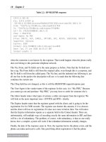
domain is advertised in the beacons, within the Mobility Domain IE, shown in Table 6.7.
Table 6.7: Mobility domain information element
Element ID Length Mobility Domain ID FT Capabilities and Policy
1 byte 1 byte 2 bytes 1 byte
Table 6.8: Authentication request/response frame body
Algorithm
Number
Authentication
Sequence
RSN IE Mobility
Domain IE
Fast BSS
Transition IE
1 byte 1 byte
variable variable variable
The Mobility Domain ID is a two-byte field, chosen by the network administrator to
uniquely identify the mobility domain, and to distinguish it from other mobility domains
that may be in the area. The FT Capabilities and Policy field specifies two bits. The first bit,
when set, enables over-the-DS transitions, which will be described shortly. The second bit,
when set, enables the use of pre-authentication resource reservations.
First, let’s look at the changes to the transition, for a completely over-the-air scenario. 802.11r
eliminates the frames that carried the four-way handshake, WMM AC resource requests, and
the 802.1X exchange for a handoff. The process for handoff thus changes from the steps
mentioned in Section 6.2.3 to the following, starting from that section’s step 5.
1. The client will send an Authentication message to the new access point, establishing
the beginnings of a relationship with this new access point, but not yet enabling data
services. This Authentication message is called an Authentication Request, and has
the structure shown in Table 6.8.
The Algorithm Number specifies equals 2 to use 802.11r. The RSN IE contains a
similar RSN IE to the Association Request for the original WPA2, except that one
PMKIDwillbegiven(justaswithopportunistickeycaching)butwiththeIDforthe
PMK-R0,andthekeymanagementsuitewillbegivenas00:0F:AC,3,meaningtouse
802.11r for the key derivation, rather than WPA2. The Mobility Domain IE matches
the one in the beacon. The Fast BSS Transition IE contains the client’s nonce, and thus
establishes a similar purpose as the first message in the 802.11i four-way handshake.
2. The access point, if it will accept the client, sends an Authentication Response
message. This Authentication message has the same structure as the Authentication
256 Chapter 6
www.newnespress.com
Request, except that the contents of the Fast BSS Transition IE are different. That IE
now contains the authenticator’s nonce, as well as repeats the client’s nonce. This
corresponds to the second message in the Four-Way handshake. At this point, the
802.11“Authentication”processisdone,but802.11risonlyhalfwaythrough.
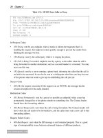
3. The client sends the access point a Reassociation Request message. This message has
all of the same fields as a normal Reassociation Request message, but also includes
the fields given in Table 6.9.
Table 6.9: Additional 802.11r fields for the Reassociation Request
RSN IE Mobility
Domain IE
Fast BSS
Transition IE
RIC
Descriptor IE
TSPEC …
variable variable variable variable variable
Here,theRSNIE’sPMKIDhasnowchangedtothatforPMK-R1,signifyingthat
this phase of the communication is now for the R1 key holder, and does not need to
involve R0 at this point. Furthermore, the Fast BSS Transition IE holds a MIC, or
secure hash, of the information elements added to the frame for 802.11r, thus
protecting the admission control requests from being forged or modified. The RIC
Descriptor IE states that one or more TSPECs are following, and that these TSPEC
information elements, which would ordinarily be a part of the ADDTS Request for
WMM Admission Control, are actually related to this transaction. Note that the
access point will choose one and only one of the multiple possible TSPECs given, as
each one is considered an alternative. In this way, the protocol of requests and
responses for TSPECs have been embedded in the Reassociation Request. This
message serves as message three of the four-way handshake.
4. The access point, if it accepts the client and the client has not failed the security
handshake, will send a Reassociation Response. The Reassociation Response carries
the usual fields, but also the same fields as in the previous Reassociation Request.
The RIC Descriptor IE from the request is returned, but with the status code within
properly set to inform the client of whether the request was accepted. On an accepted
resource request, the TSPEC that corresponds to the accepted request is returned. On
a failed request—which is still a part of a valid, successful Reassociation Request—a
TSPEC that might still work can be returned by the access point, to give the client an
option to submit an ADDTS with something that might succeed.
At this point, the client is associated, data is flowing, and the admission control request has
been either accepted or rejected. This only took four frames, and so the over-the-air
overhead has been dramatically reduced.
We can notice, however, that the first two frames of the exchange do not change where the
client is associated or how its traffic flows. They affect only the establishment of the
Voice Mobility over Wi-Fi 257
www.newnespress.com
security keys. Because of this, there is one more change that can be made, and this one can
ease the transition burden even more. Instead of the first two Authentication frames going
over the air, on the channel of the new access point, the client may have the option of
sending the contents of those frames to the current access point. This is allowed only if the
current access point states that it supports this feature in the FT Capabilities field. This type
of transition is called an over-the-DS transition. Over-the-DS transitions, named because
of the term distribution service (DS) referring to the nebulous wireline interconnection
between access points that, for standalone access point systems, is normally only a switched
Ethernet network, requires that the current access point be able to forward the messages
intended to the new access point. The added contents of the Authentication frames specified
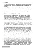
in the steps, starting from the RSN IE, are, instead, placed into an FT Action frame. The FT
Action frame has the format given in Table 6.10.
Table 6.10: FT action request/response frame body
Category Action Client
Address
Target
BSSID
RSN IE Mobility
Domain
IE
Fast BSS
Transition
IE
1 byte 1 byte 6 bytes 6 bytes
variable variable variable
The main difference between the Authentication frames and these Action frames, besides
the obvious one that the Action frames go to and from the current access point, is that the
Action frames contain the BSSID of the access point that the client wishes to hand off to. In
a mobility domain, the current access point will invoke some sort of unspecified mechanism
to get the message to the target access point, with exactly the same effects as if the message
had been sent directly to the target access point over the air. The previous list of steps reads
the same, if one just substitutes FT for Authentication and remembers that the frames are
sent to the current access point for those FT messages.
This sort of handoff is not a part of a make-before-break scheme, because there is no
commitment on the part of the client to make the transition when performed over the air or
the DS, and the data path is unambiguously owned by only one of the two access points.
6.2.5.3 Preauthentication Resource Allocation
802.11r allows for one more mode. Preauthentication resource allocation allows a client to
request resources on the new access point before leaving the old one. These resources are
requested by inserting two additional steps into the handoff, right after the Authentication/
FT Response.
These two steps, known as Authentication/FT Confirm and Authentication/FT
Acknowledgement, serve a somewhat similar purpose for resource reservation as the
258 Chapter 6
www.newnespress.com
Reassociation steps do. Essentially, the resource reservation part of the protocol is moved
forward, from the Reassociation messages to the new Confirm and Acknowledgement
messages. In this manner, the resources can be requested before the client makes the
transition, thus allowing the client to have more confidence that the resources will be
available before the transition.
An important part of the protocol is that the target access point is not required to
specifically allocate the resources that were a part of the accepted resource requests, and can
specifically deny the resource request when the client finishes the protocol with the
Reassociation Request, by rejecting the Reassociation. This flexibility exists to allow the
network to avoid certain greedy client behavior, where a client who wishes to hand off may
feel compelled to allocate resources for a second and third backup, thus hogging valuable
airtime without using it. The network, however, is allowed to take these essentially
provisional resource allocations, known as accepted rather than active resources, into
account when admitting or denying other clients.
Even with this mechanism, the handoff scheme is still one of break-before-make, as the
client is forbidden from using over-the-air data resources on two access points
simultaneously.
6.2.5.4 802.11r in Wireless Architectures
With a better understanding of the mechanisms employed in 802.11r, we can now look back
and answer the question of how this fits in across the variety of different architectures.
Because 802.11r has such a strong focus on a central authority, one might ask the question
of whether 802.11r requires a controller or can still be used for standalone access points.
Themappingtocontrollersisratherobvious.ThecontrollerneedstobetheR0KeyHolder,
andcommunicatesdirectlywiththeRADIUSserver,justaswithWPA2.TheR1Key
Holder doesn’t need to be located elsewhere, so it can be present on the controller as well,
usuallyinthesamemodule.Thisway,thetwolevelsofPMKholderscollapse,andwork
justaswiththeonePMKholderwithopportunistickeycaching.Whentheclienthandsoff
toasecondaccesspoint,thataccesspointrequeststhePTKfromthecontroller,which
generatesanewPMK-R1alongtheway,andstoresitinternallyifneededforlateruse.
Figure 6.8(a) shows one such setup. Minor alterations can be encountered, such as having
thePTKholderinthecontrollerforarchitectureswhoencrypttheirpacketscentrally.
So, how can this possibly map to a standalone access point model? Figure 6.8(b) shows one
method.ThemajorchangeisfortheremovalofanyonecentralizedPMKholder.Instead,
access points are both R0 and R1 key holders, but with the R1 key holders being different
access points from the one R0 key holder. When a client performs 802.1X for the first time,
thataccesspointbecomestheR0keyholder.Alongtheway,itgeneratesaPMK-R1anda
PTK.Butwhentheclienthandsoff,thenewaccesspointwillalsobecomeanR1key
Voice Mobility over Wi-Fi 259
www.newnespress.com
holder. The challenge in the architecture is for the system to have some sort of protocol
where the new access point can find out which other access point is the R0 key holder.
Oncethatisfound,thenewaccesspointrequestsaPMK-R1fromtheoldaccesspoint,
generatesaPTK,andstartsworking.TheidentityoftheR0keyholderdoesnotchange,
until the key expires or 802.1X is performed again. In this way, there are many R1 key
holders to each R0 key holder, and every access point can be an R0 key holder.
So, the good news is that standalone architectures can also participate in the 802.11r
protocol.
One final note about key exchanges. There is no standard in 802.11i, 802.11r, or WPA2 that
speciesjusthowthesePMKsandPTKsgetmovedaround.Everyvendorisallowedtouse
its own proprietary protocol, and they do. The only requirement is that whatever protocol is
used to move keys around provide for privacy and integrity. Controller-based architectures
already have these protocols, and so there should be no concern. For standalone access
points, a protocol will have to be created. You may have heard of 802.11F, the Inter-Access
Point Protocol (IAPP), in previous years. This withdrawn recommendation—it was not even
a standard—had tried to describe some earlier methods for communication. But it was not
adequate for more modern technologies, and the controller-based architectures had lead to
its being abandoned. Therefore, whatever protocol is created will likely be proprietary or
lightly used.
An issue also arises about 802.11r mobility domains across vendors. Mobility domains do
not extend across access points from two different vendors, even if both vendors support
802.11r. Because the key exchange protocols are vendor-specific, there is no way to connect
the access points of multiple vendors together into one mobility domain. This is not likely
to change, as there is quite a bit more to managing the security state of a client than
swapping keys, and so there would not be a one-size-fits-all protocol.
6.2.6 Network Assistance with 802.11k
In Section 6.2.1, we considered the difference between network assistance and network
control. Here, we will go through the details of the technologies that allow network
assistance to happen.
802.11k,labeled“RadioResourceMeasurement”(similarlynamedasradioresource
management [RRM], but actually distinct), is a collection of protocols designed to improve
the flow and exchange of information between the client and the access point. The basic
mechanism of 802.11k is designed around the concept of reports. These reports are
requested by one side of the conversation and furnished by the other. Many of the reports
require time to produce, mostly because they require the reporter to engage in some sort of
scanning behavior.