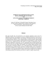
PRIME MOVERS FOR MOTOR VEHICLES docx
Bạn đang xem bản rút gọn của tài liệu. Xem và tải ngay bản đầy đủ của tài liệu tại đây (998.61 KB, 20 trang )
22
PRIME MOVERS FOR MOTOR
VEHICLES
The motion of all vehicles requires the expenditure of a certain quantity of me-
chanical energy, and in motor vehicles the system that supplies such energy (in
most cases an internal combustion engine) is on board. The lack of an adequate
prime mover is the main reason that mechanical vehicles could be built only
at the end of the industrial revolution, and enter mass production only in the
Twentieth Century, in spite of attempts dating back to ancient times.
For a mechanical vehicle to be built, a prime mover able to move not only
itself, but the vehicle structure and payload as well, was needed. Remembering
that the power needed to move the mass m at the speed V on a level surface
with coefficient of friction (sliding or rolling) f is equal to P = mgf V ,itiseasy
to conclude that the minimum value of the power/mass ratio of a prime mover
able to move itself is
P
m
=
gfV
ηα
, (22.1)
where α is the ratio between the mass of the engine and the total mass of the
vehicle and η is the total efficiency of the mechanism which transfers the power
and propels the vehicle.
Prime movers with an adequate power/mass ratio and transmission devices
with a power rating and an efficiency high enough to allow the motion of the
vehicle were not practical until the Nineteenth Century.
The engine must obtain the energy required for motion from an energy
source that is usually on board the vehicle. Rail vehicles often receive such energy
from outside, but the only road vehicles in which this occurs are trolleybusses.
In most cases, the energy is stored as the chemical energy of a fuel, but
it can be stored in the form of electrochemical energy (electrical batteries) or,
G. Genta, L. Morello, The Automotive Chassis, Volume 2: System Design, 165
Mechanical Engineering Series,
c
Springer Science+Business Media B.V. 2009
166 22. PRIME MOVERS FOR MOTOR VEHICLES
TABLE 22.1. Onboard energy storage. Energy density e/m, power density P/m and
general characteristics (data for electrochemical energy refer to lead-acid batteries).
Energy stored Chemical Electrochemical Elastic Kinetic
e/m [Wh/kg] 10,000 – 12,000 10–40 2–10 6–20
P/m [W/kg] Engine dependent 10 – 100 High Very high
Efficiency 0.2 – 0.3 0.6 – 0.85 0.7 – 0.9 0.7 – 0.95
Reversibility None Possible
Pollution Inthesiteof In the site of generation
utilization
Dependence on Almost complete The primary source can be different
liquid hydrocarbons
even if few attempts in this direction have been made, and even fewer vehicles
of this type have a practical use, as kinetic energy (flywheels) or elastic energy
(springs).
These forms of energy storage are compared in Table 22.1.
When two or more different types of energy are stored or supplied to a vehicle
that can work either with energy supplied from the outside or with energy stored
on board, and if the two modes of operation are used independently, the vehicle
is said to be bimodal. A trolleybus with batteries that allow it to go on a part of
its route where there is no power distribution is an example of a bimodal vehicle.
Vehicles with two or more methods of energy storage, in which one is used
not only to supply energy but also to store energy coming from one of the other
sources, are said to be hybrid. An example is a bus with an internal combustion
engine and batteries, in which the electric energy is also used to transform the
energy from the engine with greater efficiency and to recover braking energy.
It is also possible to have a bimodal hybrid vehicle if, in the previous exam-
ple, the energy to charge the batteries is supplied not only by the thermal engine
but also by the mains.
In vehicles there are huge quantities of energy that may be recovered. The-
oretically, all energy not dissipated (by aerodynamic drag and rolling resistance,
losses in the transmission and energy conversion) can be recovered.
If the kinetic energy or the gravitational potential energy of the vehicle is
recovered when slowing down or travelling downhill, regenerative braking occurs.
When the only form of energy storage on board is chemical energy, regen-
erative braking is not possible, while it may be implemented in the other cases
of Table 22.1. Energy recovery can, however, be only partial, not only due to
the intrinsic losses of all energy transformations, but also because of the peculiar
characteristics of braking.
The power involved in braking is hardly manageable by the device that has
to convert the energy taken from the vehicle into usable energy, except in the
case of slowing down with limited deceleration. Usually, to allow regenerative
braking, there must be two braking systems, with the traction motors (in the
case of electric vehicles) providing regenerative braking when slowing down or
travelling downhill, while a conventional braking system performs, in a non-
regenerative way, emergency or sudden decelerations
22.1 Vehicular engines 167
22.1 VEHICULAR ENGINES
The storage of energy in a liquid, less frequently gaseous, form of fuel has so
many advantages that this form of energy storage has supplanted all others
since the beginning of the Twentieth Century. The advantages of easy resupply
(recharging) and above all the very high energy density are overwhelming.
The chemical energy of the fuel (gasoline, diesel fuel, but also liquefied pe-
troleum gas (LPG), methane, alcohol, methylic or ethylic, etc.) is converted into
mechanical energy by a thermal engine. In spite of the low conversion efficiency
that characterizes all thermal engines, the actually available energy density is
about 30 ÷ 50 times greater than that of other energy storage devices. The
power density is also very high.
The first self-propelled road vehicles were built at the end of the Eighteenth
and above all at the beginning of the Nineteenth Century owing to the develop-
ment of thermal engines, in this case reciprocating steam engines. However, while
steam engines were adequate for ships and railway engines, their power/weight
ratio was too low for road vehicles. This issue, together with other technical and
non-technical factors, made steam coaches a commercial failure.
Only at the end of the Nineteenth Century did the development of recipro-
cating internal combustion engines allow the diffusion of motor vehicles.
As road vehicles began to spread, three competing types of engine were
available: steam engines, that in the interim had undergone drastic improve-
ments to become adapted to lightweight vehicles, the new internal combustion
engines, and DC electric motors combined with recently developed lead acid ac-
cumulators. For a time it looked as though the electric motor would become the
most common alternative, owing to its reliability, cleanliness, quietness and ease
of control. The various types of engine were balanced in performance, as shown
by the fact that the first car able to overcome the 100 km/h barrier in 1898 was
an electric vehicle.
However, then as today, the main drawback of the electric vehicle, its un-
satisfactory range, prevented its diffusion.
The reciprocating internal combustion engine become the main source of
power for all road vehicles, and has remained so since the first decades of the
Twentiethth Century.
In the 1960s, after the great success of turbojet and turboprop engines in
aeronautics, which would quickly almost completely replace reciprocating engines
in aircraft and helicopters, several attempts to introduce gas turbines in motor
vehicles were made. They were unsuccessful, primarily because of the strong fuel
consumption at idle.
At the same time, attempts to reintroduce the steam engine were also made,
primarily for reducing pollution and for the scarcity, then more supposed than ac-
tual, of fuels suitable for reciprocating engines. Even if steam engines were much
different from those of the previous century, the results were not satisfactory.
A further attempt to innovate, although less radical, was the introduction
of rotary internal combustion engines. Some vehicles with this innovative engine
168 22. PRIME MOVERS FOR MOTOR VEHICLES
were mass produced and had a limited commercial success, but this attempt was
likewise another failure.
It is likely that the greatest advantage of the reciprocating automotive engine
is a century of uninterrupted development, leading to performance, low cost and
reliability that could not be imagined one century ago.
Practically, every attempt to substitute a different propulsion device to solve
one of its many problems was answered with industry innovations that solved,
in an equally (or more) satisfactory way, the same problems.
The issues that fuel today’s drive to replace the internal combustion en-
gine with a prime mover of a different kind remain its dependence on liquid
hydrocarbons as fuel and the emission of pollutants and greenhouse gases.
The dependence on fuels derived from oil is characteristic of the whole eco-
nomic system, particularly in Europe and even more in Italy. Even if electric
vehicles became widespread or hydrogen took over as fuel, this problem would
remain essentially unchanged if the primary energy used to produce electric en-
ergy or hydrogen came from the combustion of oil derivatives. More precisely,
the problem would become worse, owing to lower overall energy efficiency (from
well to wheel, as is usually said).
Only a massive use of nuclear energy, possibly with some contribution from
renewable sources including hydrocarbons derived from biomasses, can radically
solve this problem.
Environmental problems due to pollutants like carbon monoxide, nitrogen
oxides, particulates, etc., all substances not necessarily produced by combustion,
have already been tackled with success and modern internal combustion engines
are much cleaner than older ones. This trend is bound to continue in the future.
Carbon dioxide, on the contrary, is the result of the type of fuel used and
can be reduced only by using fuels with lower carbon content, like methane,
and only completely eliminated by using hydrogen. However, the production of
hydrogen must use a primary source that does not produce carbon dioxide, like
nuclear energy.
Hydrogen can be used both in internal combustion engines and in fuel cells.
Fuel cells are electrochemical devices able to directly convert the energy of a
fuel-oxidizer pair into electric energy, without a combustion process taking place.
Since in this transformation there is no intermediate stage of thermal energy, the
efficiency can be, theoretically, higher than that of any thermal engine, even if
it is limited by losses of various kinds.
The reactions occurring in fuel cells are electrochemical reactions of the
kind typical of batteries. The choice of fuel is severely limited, since the use
of molecules that may be easily ionized is mandatory. Hydrogen is the most
common choice, even if methane is an interesting alternative, while the oxidizer
must be, in vehicular applications, atmospheric oxygen. The energy density of
fuel cells using liquid fuels like methanol or formic acid is too low for vehicular
applications.
The problems linked with the use of hydrogen as a fuel primarily relate to
its low volume energy density (its mass energy density is, on the contrary, quite
22.2 Internal combustion engines 169
high) and to the subsequent need to use pressurized tanks, cryogenic storage
at 20 K, or to resort to technologies like those based on metal hydrides. There
are also problems involved in its supply network. The technological problems are
being solved, since hydrogen is used in experimental vehicles as a fuel for internal
combustion engines, and in many countries there are already a number of supply
points. Safety does not seem to be a problem, since hydrogen is not much more
dangerous than a highly flammable and volatile liquid such as gasoline.
Hydrogen may also be stored on board as methanol or methane, from which
hydrogen is then obtained by chemical dissociation. This solution has the draw-
back of causing poisoning of the fuel cell catalyst if impurities due to this process
remain in the hydrogen.
At present there are many types of fuel cells, based on different types of
membranes and catalysts. They operate at different temperatures (from less
than 100
◦
C to more than 900
◦
C, the latter being unsuitable for vehicular use),
and each has its advantages and drawbacks. The technology developed in the
aerospace field (fuel cells were developed in the 1960s for the Apollo programme
andarenowusedontheSpace Shuttle) cannot be used in road vehicles. Many
problems are still to be solved, from cost to reliability, with added problems linked
to their use under the conditions of much variable load and reduced maintenance
that are typical of motor vehicles.
Until fuel cells suitable for vehicular use are available, the only way to
use electric motors is by employing accumulators. Their worst drawback is the
impossibility of obtaining high energy density and power density at the same
time. This is particularly true for lead-acid accumulators, whose energy density
decreases fast with increasing power density, that is, with increasing current.
Also, the duration and the efficiency of batteries decrease with increasing
power density. The field of batteries for vehicular propulsion has seen much re-
search activity, and the possibility of building electric vehicles with performance
not much different from that of vehicles with internal combustion engines, espe-
cially in terms of range, may yet emerge.
The possibility of using different forms of energy accumulators in a sin-
gle vehicle in a hybrid configuration is particularly interesting. There are many
experimental vehicles of this kind and some of them have been mass produced.
22.2 INTERNAL COMBUSTION ENGINES
As stated in the previous section, most road vehicles are powered by reciprocating
internal combustion engines. The performance of an internal combustion engine
is usually summarized in a single map plotted in a plane whose axes are the
rotational speed Ω
e
and either the power P
e
or the engine torque M
e
(Fig. 22.2).
Often the former is reported in rpm, the power in kW and the torque in Nm.
If a plot of the power as a function of speed is used, the plot is limited
by the curve P
e
(Ω
e
) expressing the maximum power the engine can supply as
170 22. PRIME MOVERS FOR MOTOR VEHICLES
a function of the speed. Such a curve is typical of any particular engine and
must be obtained experimentally. However, when building a simple model of the
vehicle, it is possible to approximate it with a polynomial, usually with terms
up to the third power,
P
e
=
3
i=0
P
i
Ω
i
e
. (22.2)
The values of coefficients P
i
can easily be obtained from experimental test-
ing. In the literature it is possible to find some values of the coefficients which
can be used as a first rough approximation. M.D. Artamonov et al.
1
suggest the
values
P
0
=0,P
3
= −
P
max
Ω
3
max
for all types of internal combustion engines and
P
1
=
P
max
Ω
max
,P
2
=
P
max
Ω
2
max
,
for spark ignition engines,
P
1
=0.6
P
max
Ω
max
,P
2
=1.4
P
max
Ω
2
max
for indirect injection diesel engines and
P
1
=0.87
P
max
Ω
max
,P
2
=1.13
P
max
Ω
2
max
for direct injection diesel engines.
In these formulae Ω
max
is the speed at which the power reaches its maximum
value P
max
.
The driving torque of the engine is simply
M
e
=
P
e
Ω
e
, (22.3)
or, if the cubic polynomial is used and coefficient P
0
vanishes,
M
e
=
3
i=1
P
i
Ω
i−1
e
. (22.4)
At present, internal combustion engines for vehicular use are controlled by
systems of increasing complexity and their performance is increasingly dependent
on the control logic used. The power and torque maps are, then, not unique for
a certain engine but may be changed simply by modifying the programming of
1
M.D. Artamonov et al. Motor vehicles, fundamentals and design, Mir, Moscow, 1976.
22.2 Internal combustion engines 171
the electronic control unit (ECU). If the above mentioned equations have always
been just a rough approximation, today the situation is even more complex from
this point of view, and in some cases the equations may supply results much
different from those actually observed.
If experimental results on a similar engine are available, it is possible to
obtain the maximum power curve from the power curve of that engine.
Remark 22.1 The practice of correcting engine performance in a way propor-
tional to the displacement is not correct, even if it is acceptable and often used
for small changes of capacity. A scaling parameter that may be more correct is
the area of the piston multiplied by the number of cylinders, that is, the ratio
between capacity and stroke.
Themeaneffectivepressurep
me
, i.e., the ratio between the work performed
in a complete cycle and the capacity of the engine, is often used instead of the
torque. In four-stroke engines it is defined as
p
me
=
4πM
e
V
, (22.5)
where V is the total capacity of the engine.
All points below the maximum power curve are possible working points for
the engine, when it operates with the throttle partially open.
Remark 22.2 Since the engine is seldom used at full throttle, usually only when
maximum acceleration is required, the conditions of greatest statistical signifi-
cance are those at much reduced throttle.
A diagram of the specific fuel consumption of a direct injection diesel engine
with a capacity of about 2 liters is shown in Fig. 22.1; on the same plot, the circles
show the points at which the engine operates on the driving cycle used in Europe
for computing fuel consumption for a car with a reference mass of 1600 kg.
The percentages shown close to the circles refer to the time the engine is
used in the conditions related to their centers, with reference to the total time
the engine is producing power (the time at idle is then not accounted for); the
center of the circles represents the average of all utilization points in a rectangle
with sides of 500 rpm on the speed axis and one bar on the p
me
axis.
The curves below the one related to the maximum mean effective pressure
in the plot of Fig. 22.1 are those characterized by various values of the specific
fuel consumption q. The correct S.I. units for the specific fuel consumption, the
ratio between the mass fuel consumption (i.e., the mass of fuel consumed in
the unit time) and the power supplied, is kg/J, i.e. s
2
/m
2
, while the common
practical units are still g/HPh or g/kWh. If the thermal value of the fuel is equal
to 4.4 × 10
7
J/kg, it follows that
172 22. PRIME MOVERS FOR MOTOR VEHICLES
FIGURE 22.1. Map of a direct injection diesel internal combustion engine of about 2
liters capacity, with constant specific fuel consumption curves. The circles show the
points where the engine operates on the driving cycle used in Europe for computing
fuel consumption with a car with a reference mass of 1600 kg. The consumption of this
engine at idle is about 0.62 l/h.
q =
2.272 × 10
−8
η
e
kg/J =
60.16
η
e
g/HPh =
81.79
η
e
g/kWh ,
where η
e
is the efficiency of the engine.
This map allows the fuel consumption of the engine to be stated in various
working conditions: at far left is the minimum speed at which the engine works
regularly; at far right is the maximum speed. The speed axis shows conditions at
idle, where the mean effective pressure (p
me
) vanishes together with the efficiency
and the specific fuel consumption is infinite.
The map can be represented in a different way, plotting power on the ordi-
nates and using the efficiency η
e
of total energy conversion, from chemical energy
of the fuel to mechanical energy at the shaft, as a parameter.
A plot of this type is shown in Fig. 22.2.
22.2 Internal combustion engines 173
FIGURE 22.2. Map of a spark ignition internal combustion engine, with constant effi-
ciency curves.
Remark 22.3 The efficiency of a spark ignition engine reaches its maximum in
conditions close to full throttle and at a speed close to the one where the torque
is at its maximum. The efficiency decreases quickly as power is reduced at a fixed
speed. This decrease is less severe in diesel engines.
Efficiency and specific fuel consumption are linked by the relationship
q =
1
Hη
e
(22.6)
where H is the thermal value of the fuel.
Example 22.1 Compute the coefficients of a cubic polynomial approximating
the power versus speed curve of the engine of the vehicle in Appendix E.1. Com-
pare the curve so obtained with the experimental one and that obtained from the
coefficients suggested by Artamonov. Plot on the same chart the engine torque
and the specific fuel consumption. By taking from the plot points spaced by 250
rpm and using a standard least squares procedure, it follows that
P = −10, 628 + 0, 1506Ω − 9, 5436 × 10
−5
Ω
2
− 5, 0521 × 10
−8
Ω
3
,
where Ω is expressed in rad/s and P in kW. Using Artamonov’s coefficients for
a spark ignition engine, the equation becomes
P =0, 7024Ω + 1, 290 ×10
−4
Ω
2
− 2, 369 × 10
−7
Ω
3
.
The two curves are plotted in Fig. 22.3. Both expressions approximate the ex-
perimental curve well, even if the coefficients are quite different.
174 22. PRIME MOVERS FOR MOTOR VEHICLES
FIGURE 22.3. Engine power curve for the car of Appendix E.1. (1) Experimental
curve, (2) third-power least square fit, (3) cubic polynomial with coefficients computed
as suggested by Artamonov et al. The torque and the specific fuel consumption are also
reported as functions of speed.
Two more examples of engine maps for two spark ignition engines of about
2 l capacity are reported in Figures 22.4 and 22.5. The first refers to an indirect
injection engine (in the intake manifold), while the second one is for a direct
injection (in the combustion chamber) engine. The latter is similar to the diesel
engine shown earlier.
Remark 22.4 When the fuel consumption is needed in points different from
those shown in the plot, it is advisable not to interpolate in the map of specific fuel
consumption, but on that of efficiency. The consumption changes in a strongly
nonlinear way with both speed and mean effective pressure, and tends to infinity
when the p
me
tends to zero. The efficiency, on the contrary, tends to zero, when
the p
me
tends to zero.
22.3 ELECTRIC VEHICLES
Batteries and electric motors are the most common alternative to internal com-
bustion engines. As already stated, the performance obtainable is lower than that
typical of vehicles with internal combustion engines, especially in terms of range,
but also in terms of operating costs and vehicle availability. Studies on batteries
for vehicular use are very active, and it is a common opinion that only through
electric vehicles will some of the problems caused by the use of motor vehicles in
urban areas be solved. The performance of some of the batteries suggested in-
stead of the more common lead-acid batteries are reported in Table 22.2. Future
progress seems to be linked more to the possibility of mass producing accumula-
tors with sufficient performance at costs compatible with vehicular use than to
an increase of performance.
22.3 Electric vehicles 175
FIGURE 22.4. Map of the specific fuel consumption of an indirect injection spark
ignition engine of about 2 liters capacity. The consumption of this engine at idle is
about 0.92 l/h.
The advantages of electric vehicles are linked primarily to the possibility
of moving the pollution from where the vehicle is used to where the power is
generated, taking advantage of the better pollution control of power stations
versus small engines. Another advantage is the possibility of regenerative braking.
The performance of electric drives is, however, decreased by losses in both the
engine and the batteries, and above all by the difficulties that batteries have
in accepting the high power bursts occurring in braking. The disadvantages are
also well known: The reduced range and duration of batteries and their high
mass. However, even today, the performance of electric vehicles is sufficient for
urban use.
From the point of view of energy the advantages of battery powered electric
vehicles (BEV) are still in doubt: When the primary source is a fossil fuel, in
spite of the greater efficiency of the primary conversion and regenerative braking,
the overall consumption is comparable to that of internal combustion engines.
The very fact that the thermo-mechanical conversion occurs far from the vehicle
makes it impossible to use waste heat for heating, and this makes the energy
balance worse.
176 22. PRIME MOVERS FOR MOTOR VEHICLES
FIGURE 22.5. Map of the specific fuel consumption of a direct injection spark ignition
engine of about 2 liters capacity. The consumption of this engine at idle is about 0.90
l/h.
TABLE 22.2. Main characteristics of some battery types for automotive use (M.J.
Riezenman, The great battery barrier, IEEE Spectrum, Nov. 1992). a): Constant current
3 hours discharge. b): Cycles with 80% discharge depth. c): 100% discharge depth in
urban cycle. d): 80% discharge
Type E/m
a
P/m
b
Efficiency Life
c
[Wh/kg] [W/kg] [cycles]
Sodium-sulphur 81 152 91 % 592
Sodium-sulphur 79 90 88 % 795
Lithium-sulphides 66 64 81 % 163
d
Zinc-bromine 79 40 75 % 334
Nickel-zinc 67 105 77 % 114
Nickel-metal hydrides 54 186 80 % 333
Nickel-metal hydrides 57 209 74 % 108
Nickel-metal hydrides 55 152 80 % 380
Nickel-iron 51 99 58 % 918
22.3 Electric vehicles 177
FIGURE 22.6. Map of the efficiency of an induction AC motor with a nominal power
of 35 kW.
The traditional configuration is based on direct current (DC) or alternating
current (AC) motors connected to the wheels through a transmission of more or
less conventional type. Since the electric motor can start under load, there is no
need for a clutch and usually no need for a gearbox with various transmission
ratios; only a reduction gear and a differential are necessary. The motor is con-
trolled with power electronic devices (choppers) whose efficiency is at present
extremely high.
Instead of a DC motor (with brushes) it is possible to use an AC motor,
controlled by an inverter.
The map of the efficiency of an induction AC motor with a nominal power
of 35 kW is shown in Fig. 22.6.
Recently permanent magnet synchronous brushless motors with related con-
trol electronics have also been used in vehicular applications. The efficiency and
control are generally better, and the cost is transferred from the motor to the
power electronics.
As an alternative to the traditional architecture, with the motor operating
the wheels through a mechanical transmission, it is possible to put two or more
motors directly in the wheels. This is a configuration suggested and tried sev-
eral times in the past with limited success except for special vehicles, and it is
one that seems to be ready for large scale application today. Traditional CC or
AC motors require a mechanical transmission in any case, since they supply an
insufficient torque and operate at a speed that is higher than that of the wheels.
At present, high torque motors (torque motors, both with internal and external
rotor) are available; these can be connected directly to the wheels without in-
terposing a reduction gear. Apart from the advantage, which may be important
in some applications, of allowing an arbitrarily large steering angle, even up to
360
◦
, putting the motor in the wheels without using a reduction gear leads to
high efficiency, low noise and a large degree of freedom in placing the various
subsystems of the vehicle.
178 22. PRIME MOVERS FOR MOTOR VEHICLES
The motor control system can perform the electronic differential function,
distributing the torque to the wheels of an axle, and may do so by simulating all
the functions of limited slip (or in general of controlled) differentials. However,
to put the motors in the wheels increases the unsprung mass, even if in recent
applications such mass increase is not large, and may not be detrimental to
comfort. The motors may also be located close to the wheels but fixed to the
body, and connected to the wheels using transmission shafts. The reduction of the
unsprung mass is compensated by reintroducing transmission shafts and above
all joints, which work with a relative displacement of the two parts.
22.4 HYBRID VEHICLES
While the only accumulators able to store all the energy required for motion
are electrochemical, the quantity of energy to be accumulated in the secondary
accumulators of hybrid systems is lower, and this may allow devices of other
types to be used. The drawbacks of electrochemical batteries become also less
severe.
Elastic energy can be stored in a solid or in a gas. In the first case, the
energy density e/m of the device is
e
m
= α
1
K
σ
2
ρE
, (22.7)
where α
1
and K are coefficients linked to the ratio of the mass of the energy
storage elements and that of the whole device, and to the shape of the storage
element and the stress distribution, with σ the maximum stress in the energy
storing element and E the Young’s modulus of the material.
Material with very high strength (spring steel) or low stiffness (elastomers)
must be used. The latter are particularly well suited, since some of them may be
stretched up to 500% with a good fatigue life and limited energy losses.
The use of a compressed gas, while considered for fixed installations, has
several disadvantages for vehicular uses, due to its lower efficiency, the high mass
of the container of pressurized fluid, and burst danger. Hydraulic accumulators,
in which the energy is stored in the walls of an elastomeric vessel full of fluid, have
been suggested and tested in connection with hydraulic motors and pumps. The
pressure of the oil, however, is controlled by the characteristics of the elastomeric
material independent of driving or braking (in case of regenerative braking)
torque. Reversible variable displacement motors, which are quite complex and
costly, are then required.
Energy can be stored in the form of kinetic energy in a flywheel. The energy
density of a kinetic energy accumulator can be expressed as
e
m
= α
1
α
2
K
σ
ρ
, (22.8)
22.4 Hybrid vehicles 179
where α
1
, α
2
and K are coefficients linked with the ratio of the mass of the fly-
wheel and that of the whole system, to the depth of discharge actually performed
and to the shape and the stress distribution in the flywheel. σ is the maximum
stress in the energy storing element and ρ is the density of the material.
Apart from some applications, like the city busses built by Oerlikon in the
1950s and actually used in public service, flywheels are now considered for use
only in hybrid systems. Their potentially high power density makes them very
suitable for supplying short bursts of power for acceleration or for storing braking
energy.
Nor is the problem of designing an adequate transmission trivial: the veloc-
ity of the vehicle must be variable at the will of the driver down to a full stop,
while the angular velocity of the flywheel is proportional to the square root of
the energy it contains. The flywheel reaches its maximum speed after recover-
ing all the energy of the vehicle, when the latter stops. This demands complex
continuous transmissions that may offset the advantages of this solution
Some possible schemes for hybrid vehicles are the following (Fig. 22.7):
a) internal combustion engine − electric accumulator,
b) internal combustion engine − elastic accumulator,
c) internal combustion engine − flywheel,
d) electric accumulator − flywheel,
e) internal combustion engine − electric accumulator − flywheel.
The first three systems are similar, at least in principle. The thermal engine
supplies the average power, working in conditions that may be optimized in terms
of efficiency or pollution. A trade-off between these requirements can be made.
FIGURE 22.7. Some possible schemes of hybrid vehicles B, batteries; C, control unit;
EG, electric generator; F, flywheel; HA, hydraulic accumulator; HM, hydraulic mo-
tor; ICE, internal combustion engine; MG electric motor/generator; MT, mechanical
transmission; P, pump; W wheels.
180 22. PRIME MOVERS FOR MOTOR VEHICLES
When the duty cycle includes frequent accelerations and braking, the advan-
tages of disconnecting the instantaneous power requirements from the working
conditions of the thermal engine, and of making regenerative braking possible,
are large. The possibility of using a far smaller engine allows one to keep mass
and cost within the limits of conventional systems or even to obtain mass and
cost savings.
The solutions (a) above in Fig. 22.7 are based on an internal combustion
engine and electric batteries. The Prius built by Toyota is an example of a hybrid
vehicle of this type (see below).
Remark 22.5 Hybrid vehicles with internal combustion engine and batteries
appear the worst alternative in theory, since electric accumulators work exactly
in the way which should be avoided, being called to supply high power for short
periods; nevertheless this is the only system used in practice today.
Solution (a
1
) is the most interesting, since the presence of an axle controlled
by a thermal engine and one controlled by electric motors allows side advantages,
like fully controlled 4WD and an active differential on the electric axle, as effec-
tive as a VDC system, to be obtained.
Solution (b) may be used in hydrostatic transmissions; owing to the cost of
the latter, it is mainly considered for large city buses.
Solution (c) allows the use of a mechanical transmission, although the re-
quirement of an efficient CVT with a wide range of transmission ratios is not
easy to meet. The very high efficiency and power density of flywheels can be
exploited.
Solution (d) is very interesting, since the flywheel manages the power peaks
occurring during acceleration and regenerative braking, allowing the use of bat-
teries with low power density, thus increasing the efficiency, and hence the range,
of the vehicle, and the life cycle of the batteries.
Solution (e) combines the advantages of (a) and (d): The batteries work in
optimal conditions, and hence a smaller mass of batteries than in (a) is required.
The presence of the batteries allows a far larger engine-off range than in (c), to
cope with conditions in which the use of an internal combustion engine is not
allowed (here it behaves like a zero-emission vehicle), while the latter allows a
practically unlimited range outside these conditions.
In actual use, as already stated, the configurations considered for applica-
tions are those based on an internal combustion engine plus electrical batteries
only, labelled as (a) in the figure.
The other solutions are more suitable for particular types of vehicles, like
city busses, heavy industrial vehicles, working machines and military vehicles.
Vehicles with electric transmission (electric generator connected to the en-
gine and electric motor driving the wheels) without any energy storage system
are sometimes defined as hybrid. This configuration has been used for decades
in diesel electric systems, and much used in rail transportation. The lack of
22.4 Hybrid vehicles 181
a storage device makes it impossible to perform regenerative braking. Often a
solution of this type is called a Fake Hybrid (FH).
True hybrid vehicles are subdivided into parallel hybrids (PH, Fig. 22.7a1)
and series hybrids (SH, Fig. 22.7a2).
In series hybrids, at least a part of the energy generated by the thermal
engine is transformed into electric energy and used to recharge the batteries, or
stored in the designated way.
In parallel hybrids, the electric energy (or the accumulated energy) does
not interact with the internal combustion engine, but comes only from recovered
energy.
Remark 22.6 The difference between the two types of hybrids does not depend
so much on the configuration shown in Fig. 22.7, but mostly on the strategy of
the controller.
The advantage of parallel architecture is its simple layout and the possibility
of being offered as an option on a conventional vehicle. A traditional rear wheel
drive vehicle may be transformed into a parallel hybrid just by adding an electric
motor operating the front wheels and a battery, along with the necessary control
system.
Another possible advantage of parallel hybrid systems is the higher efficiency
with which the power flowing through mechanical transmission is transferred to
the wheels.
Another distinction is between weak hybrids (WH) and strong hybrids (SH).
In weak hybrids the vehicle usually works with the thermal engine, while
the electric motor is used to increase performance, when needed, and above all
to restart the engine, also working as a generator for regenerative braking. The
internal combustion engine is thus switched off when the vehicle stops even for
a short time, or supplies only a very small amount of power (restart systems).
The layout of Fig. 22.7a3 is that of a conventional vehicle with starter motor
and generator integrated in a single unit and an oversized battery.
In the case of strong hybrids, the capacity of the battery is such as to
allow both a non-negligible power increase and a certain engine off range. The
instant needs of the vehicle can therefore be completely uncoupled from the
power supplied by the engine, to the point that it is even possible to avoid a
gearbox.
Finally, there are Plug-capable Hybrid Electric Vehicles (PHEV) that use a
battery that can be recharged from an external source, so that the vehicle can
operate like a true Battery Electric Vehicle (BEV) as well. It is possible to speak
of a weak version, where the engine-off operation is limited to low speed and
short range, and a strong version that may operate in engine-off mode at higher
speed with a larger range.
The possibilities offered by the various hybrid layouts are summarized in
Table 22.3
182 22. PRIME MOVERS FOR MOTOR VEHICLES
TABLE 22.3. From conventional to hybrid and electric vehicles.
Type Regenerative Battery Rechargeable Primary el. Indep. of
braking operation traction fossil fuels
Normal - FH – – – – –
PH(W) X – – – –
PH(S) X X – – –
PHEV(W) X X X – –
PHEV(S) X X X X –
BEV X X X X X
FIGURE 22.8. Layout of the hybrid power system of the Toyota Prius; ICE: thermal
engine, C: automatic clutch, G: generator, EM: driving electric motor, PG: planetary
gear, Ch: chain driving the final gear at the differential D.
One of the few hybrid vehicles that went beyond the research phase and
entered the market at a reasonable price is the Toyota Prius. Its hybrid system
is sketched in Fig. 22.8.
In the figure, ICE is the thermal engine, C is an automatic clutch, G a
generator, EM a traction electric motor, PG a planetary gear, Ch a chain con-
trolling the gear ratio of the final drive of the differential D. Note that there is
no gearbox between the thermal engine and the transmission to the wheels
2
.
2
M. Duoba et al., In-situ mapping and Analysis of the Toyota Prius HEV Engine, SAE
Paper 2000-01-3096
22.4 Hybrid vehicles 183
If τ
o
is the gear ratio on the planetary gear when the carrier is fixed (here
the carrier is connected to the thermal engine), it follows that
τ
o
= −
n
a
n
s
, (22.9)
where n
a
and n
s
are the number of teeth of the crown and the sun ; the sign is
minus since, when the carrier is fixed, the crown and the sun rotate in opposite
directions.
The simple equation
−
1
τ
o
Ω
G
+Ω
EM
=(1−
1
τ
o
)Ω
ICE
, (22.10)
where the angular velocities of the various elements are Ω
G
,Ω
EM
and Ω
ICE
,
can be written.
In the same way, by indicating with M
G
, M
EM
and M
ICE
the torques acting
on the same elements, it is possible to write
M
T
− M
EM
= M
ICE
− M
G
,
(M
T
− M
EM
)Ω
EM
= M
ICE
Ω
ICE
− M
G
Ω
G
.
(22.11)
These equations have been obtained by stating the equilibrium for rotation
of the gears and the conservation of the power that goes through it. M
T
is the
available torque on the gear wheel driving the chain Ch. By eliminating one of
the three equations, it follows that
M
G
= M
ICE
1
τ
o
− 1
, (22.12)
M
T
= M
EM
− τ
o
M
G
. (22.13)
This system works both as a parallel and a series hybrid.
The angular velocity of the thermal engine adapts to that of the vehicle by
changing the speed of the generator, following Eq. (22.10), something that can
occur only by subtracting a torque, through the generator, following Eq. (22.12).
By doing this, some power from the thermal engine charges the battery, as in
the series layout.
At low speed, a part of the power needed for motion is supplied by the
electric motor, which takes it from the battery. Finally, at a very low speed only
the electric motor operates, as in parallel layouts. This also occurs when the
speed of the thermal engine can adapt itself to that of the vehicle, without the
generator subtracting any power.
When the vehicle slows down, the available kinetic energy is recovered.
This method allows the working range of the thermal engine to be restricted
to that where minimum fuel consumption is obtained, for a given power require-
ment. It is also possible to stop the engine when the vehicle stops and to restart it
easily at a speed greater than those at which conventional starter motors operate,
owing to the generator that is now used as a motor.
184 22. PRIME MOVERS FOR MOTOR VEHICLES
The batteries are never recharged from outside the vehicle.
The fuel consumption, obtained using a gasoline engine (Atkinson cycle),
is similar to that of a diesel vehicle with similar performance; CO
2
emissions
are lower, due to the lower quantity of carbon contained in the same volume
of gasoline; other emissions are much lower, due to the reduced working of the
engine in variable conditions owing to the more constant use of the thermal
engine made possible by the hybrid layout.