Model-Based Design for Embedded Systems- P61 ppsx
Bạn đang xem bản rút gọn của tài liệu. Xem và tải ngay bản đầy đủ của tài liệu tại đây (522.48 KB, 10 trang )
Nicolescu/Model-Based Design for Embedded Systems 67842_C018 Finals Page 586 2009-10-1
586 Model-Based Design for Embedded Systems
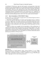
Radio
transceiver
Wakeup
radio
Low-level
packet handling
Energy supply
management
Node power
management
SoC/SiP
Sensor
interfaces
MAC
layer(s)
Oscillators
wakeup timers
Microcontroller
Upper layer
protocols
Security
functions
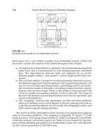
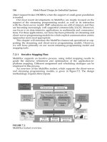
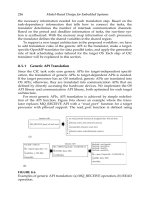
FIGURE 18.1
A node of a sensor network serving as an example of an E-AMS architecture.
step-by-step leads to an implementation. In this approach, it is crucial to
obtain very early feedback on the impact of nonideal properties onto overall
system performance, which requires considering interaction of HW/SW and
AMS subsystems.
In the SW engineering community, extreme programming [17] uses a
stepwise approach that starts with code fragments that are successively
“refined” by SW engineers. Refinement of SW systems has been known for
a long time (e.g., [15]). However, the SW-oriented approaches are restricted
to pure SW systems and do not deal with specific problems in the design of
E-AMS systems. In the realm of formal “property refinement” of embedded
systems, a (formal) property that is present and proved in a system spec-
ification is maintained by proved design steps (e.g., [16]). In this chapter,
we describe a design refinement approach for E-AMS systems. Similar to
extreme programming, and in the same vein of “property refinement,” it is
an incremental approach. Compared to extreme programming, however, it
is more specifically tailored to E-AMS system design, whereas compared to
property refinement we do not intend to provide a formal proof.
18.1.1 Previous Work
SystemC [1] supports the refinement of HW/SW systems down to RTL
by providing a discrete-event (DE) simulation framework. Design refine-
ment of HW/SW systems starts with a functional, untimed specification that
Nicolescu/Model-Based Design for Embedded Systems 67842_C018 Finals Page 587 2009-10-1
Design Refinement of Embedded Mixed-Signal Systems 587
is successively augmented with timing information, power consumption,
and more accurate modeling of communication and simulation of poten-
tial HW/SW architectures. However, the properties of E-AMS systems are
much more diverse than only timing, performance, and power consump-
tion. A key issue is the accuracy that is determined by noise, sampling fre-
quencies, quantization, and very complex, nonlinear dependencies between
subsystems: Often, accuracy of the AMS part is improved by digital signal
processing (DSP) software in the HW/SW part. SystemC offers neither an
appropriate methodology for refinement of E-AMS nor support for the mod-
eling and simulation of analog, continuous-time systems.
Support for modeling and simulation of E-AMS systems is offered
by tools such as Simulink
R
[3] and Ptolemy II [4]. While their support
for system-level design also facilitates capturing continuous-time behavior,
these tools lack appropriate support for the design of HW/SW (sub)systems
at the architecture level in a manner that, for example, SystemC does.
Hardware description languages (HDLs) dedicated to the design of AMS
systems such as VHDL-AMS [5] and Verilog-AMS [6] target the design of
mixed-signal subsystems close to implementation level such as analog/dig-
ital (A/D) converters, but modeling HW/SW systems based on HDLs is
cumbersome. To support HW/SW system design, cosimulation solution
frameworks mix SystemC and Verilog/VHDL-AMS. However, although the
resulting heterogeneous framework allows designers the modeling of mixed
HW/SW and AMS architectures, it does not support interactive evaluation
of different potential architectures in a seamless design refinement flow.
18.1.2 Design Refinement of E-AMS Systems with OSCI
AMS Extensions
An earlier work by the open SystemC initiative (OSCI) [12] presented an
AMS extension that augments SystemC with the ability to model and sim-
ulate AMS subsystems at functional and architectural level [7,8]. Further-
more, this work specifically intends to support design refinement of E-AMS.
Design refinement of E-AMS starts with a functional description that is used
as an “executable specification.” In “architecture exploration,” properties of
different subsystems such as
• Noise, distortions, and limitation effects
• Quantization and sampling frequencies
• Partitioning of (A/D/SW)
are added to the functional specification. The impact of these properties on
the overall system performance (accuracy, power consumption, etc.) is deter-
mined by modeling and simulation.
In this chapter, we assume that the reader is familiar with SystemC 2.0.
We first present a brief overview of the SystemC AMS extensions. A more
detailed overview of the AMS extensions is provided in [9,12]. Then, we
Nicolescu/Model-Based Design for Embedded Systems 67842_C018 Finals Page 588 2009-10-1
588 Model-Based Design for Embedded Systems
describe typical use cases of SystemC AMS extensions to focus on architec-
ture exploration and to classify different levels of refinement and refinement
activities.
18.2 OSCI SystemC-AMS Extensions
The SystemC AMS extensions provide support for signal flow, data flow, and
electrical networks, as shown in Figure 18.2. Electrical networks and signal-
flow models use a linear differential and algebraicequation (DAE) solver that
solves the equation system and that is synchronized with the SystemC ker-
nel. The use of a linear DAE solver restricts networks and signal-flow com-
ponents to linear models in order to provide high simulation performance.
Data-flow simulation is accelerated using a static schedule that is computed
before simulation starts. This schedule is activated in discrete time steps,
where synchronization with the SystemC kernel introduces timed semantics.
It is therefore called “timed” data flow (TDF).
The SystemC AMS extensions define new language constructs identified
by the prefix sca_. They are declared in dedicated namespaces sca_tdf
(TDF), sca_eln (electrical linear networks (ELN)), and sca_lsf (linear
signal flow (LSF)) according to the underlying semantics. By using names-
paces, similar primitives as in SystemC are defined to denote ports, inter-
faces, signals, and modules. For example, a TDF input port is an object of
class sca_tdf::sca_in<type>.
LSF and linear electrical networks (LEN) are specified by instantiating
components of the AMS extensions library such as resistors, capacitors, and
SystemC
methodology-
specific
elements
transaction
level
modeling,
cycle bit
accurate
modeling
Application
written by the end user
AMS methodology-specific elements
elements for AMS design refinement, etc
–
Linear signal
flow (LSF)
modules
ports
signals
Electrical linear
networks (ELN)
modules
terminals
nodes
Linear DAE solver
Synchronization layer
SystemC language and C/C++ language
User-defined
AMS extensions
modules, ports
signals
(e_g_aditional
solvers/
simulators)
Timed data
flow (TDF)
modules
ports
signals
Scheduler
etc_
FIGURE 18.2
AMS extensions for the SystemC language standard.
Nicolescu/Model-Based Design for Embedded Systems 67842_C018 Finals Page 589 2009-10-1
Design Refinement of Embedded Mixed-Signal Systems 589
(controlled) current sources for LEN or integrators and adders for LSF. TDF
requires some new syntactic elements and is crucial for understanding the
SystemC AMS extensions. In the following, we will concentrate on TDF
models.
TDF models consist of TDF modules that are connected via TDF signals
using TDF ports. Connected TDF modules form a contiguous graph structure
called TDF cluster. Clusters must not have cycles without delays, and each
TDF signal must have one source. A cluster is activated in discrete time steps.
The behavior of a TDF module is specified by overloading the predefined
methods set_attributes(), initialize(),andprocessing():
• The method set_attributes() is used to specify attributes such as
rates, delays, and time steps of TDF ports and modules.
• The method initialize() is used to specify initial conditions. It is
executed once before the simulation starts.
• The method processing() describes time–domain behavior of the
module. It is executed with each activation of the TDF module during
the simulation.
It is expected that there is at least one definition of the time step value and,
in the case of cycles, one definition of a delay value per cycle. TDF ports are
single-rate by default. It is the task of the elaboration phase to compute and
propagate consistent values for the time steps to all TDF ports and modules.
Before simulation, the scheduler determines a schedule that defines the order
of activation of the TDF modules, taking into account the rates, delays, and
time steps. During simulation, the processing() methods are executed
at discrete time steps. Example 18.1 shows the TDF model of a mixer. The
processing() method will be executed every 1μs.
SCA_TDF_MODULE(mixer) // TDF primitive module definition
{
sca_tdf::sca_in<double> rf_in, lo_in; // TDF in ports
sca_tdf::sca_out<double> if_out; // TDF out ports
void set_attributes()
{
set_timestep(1.0, SC_US); // time between activations
}
void processing() // executed at each activation
{
if_out.write( rf_in.read()
*
lo_in.read() );
}
SCA_CTOR(mixer) {}
};
Example 18.1 TDF model of a mixer. Predefined converter ports
(sca_tdf::
sc_out or sca_tdf::sc_in)
can establish a connection to a SystemC DE
channel, for instance,
sc_signal
<
T
>, to read or write values during the first
Nicolescu/Model-Based Design for Embedded Systems 67842_C018 Finals Page 590 2009-10-1
590 Model-Based Design for Embedded Systems
delta cycle of the current SystemC time step. Example 18.2 illustrates the use of
such a converter port in a TDF module modeling a simple A/D converter with an
output port to which a SystemC DE channel can be bound. This A/D converter also
scales the input values based on a given input range to fit the range of the output
data type, while clipping the inputs out of range.
SCA_TDF_MODULE(ad_converter) // simple AD converter
{
sca_tdf::sca_in<double> in_tdf; // TDF port
sca_tdf::sc_out<sc_dt::sc_uint<12> > out_de;
// converter port to DE domain
double in_range_min, in_range_max; // expected range of
input values
double scaleFactor; // scaling factor due to input range
void processing()
{
double val;
if(in_tdf.read() > in_range_max) val = pow(2,12)-1;
// clip if
else if(in_tdf.read() < in_range_min) val = 0;
// necessary
else val = (in_tdf.read() - in_range_min)
*
scaleFactor;
// scale otherwise
out_de.write( static_cast<sc_dt::sc_uint<12> >(val) );
{
ad_converter(sc_module_name n, double _in_range_min,
double _in_range_max)
{
in_range_min = _in_range_min;
in_range_max = _in_range_max;
scaleFactor = (pow(2,12)-1)/(in_range_max - in_range_min);
{
};
Example 18.2 TDF model of a simple A/D converter using a converter port. The
SystemC AMS simulation kernel uses its own simulation time t
TDF
that usually
differs from the SystemC simulation time t
DE
. If a pure TDF model is used in a
simulation, the SystemC AMS simulation kernel blocks the DE kernel, and so the DE
simulation time does not proceed at all. That is, in general we have t
TDF
≥t
DE
.Ina
mixedTDF-DEmodel,interconnectedbyconverterports,thereisof coursetheneedfor
synchronization.Ifthereis anaccesstoaconverterportwithintheprocessing() method
of a TDF module, the SystemC AMS simulation kernel interrupts the execution of
the static schedule of TDF modules and yields control to the SystemC DE simulation
kernel, such that the DE part of the model can now execute, effectively proceeding t
DE
until it is equal to t
TDF
. Now, the DE modules reading from signals driven by TDF
Nicolescu/Model-Based Design for Embedded Systems 67842_C018 Finals Page 591 2009-10-1
Design Refinement of Embedded Mixed-Signal Systems 591
26 ms 32 ms
26
Token
v
alid at
t
DE
t
TDF
t
TDF
Synchronization
Timestep =6 ms
TDF-module M
1
Rate 3 Rate 2
t
DE
28 30 32 34 36 38 40 42 26
p
2
p
1
29 32 35 38 41 msms
20 ms 38 ms 20 ms
38 ms
38 ms 26 ms 32 ms 38 ms
FIGURE 18.3
Synchronization between t
TDF
↔ t
DE
.
modules can read their new values at the correct time, and TDF modules reading from
signals driven by DE modules can read their correct current values.
Figure 18.3 shows an example using a TDF module M
1
with input rate 3,
output rate 2, and a time step of 6 ms. The data tokens consumed are on the
left-hand axis, and those produced are on the right-hand axis. The numbers
below the tokens denote the time (in ms) at which the respective token is
valid. The time spans above the tokens indicate the values of t
TDF
when the
respective tokens are consumed and produced, respectively. The time spans
below indicate the according values for t
DE
. At the beginning of the exam-
ple, t
TDF
> t
DE
already holds until t
TDF
= 38 ms. Then the SystemC-AMS sim-
ulation kernel initiates synchronization, for example because M
1
contains a
converter port that it accesses at this time or because another TDF module
within the same TDF cluster accesses its converter port.
It has to be underlined that SystemC AMS extensions are recently avail-
able as beta version and are under public review. This means that language
features may change. In the current draft standard, for example, name spaces
are introduced and the keywords are slightly changed.
18.3 Design Refinement of Embedded Analog/Digital
Systems
To increase design productivity, it is not sufficient to just use the AMS exten-
sions in the same way as, for example, VHDL-AMS was used. The most
important thing is to use the new language in a design methodology that
enables designers to fully take advantage of the new features of SystemC
AMS extension.
18.3.1 Use Cases of SystemC AMS Extensions
System AMS extensions are extensively applicable to all design issues of
E-AMS systems at the architecture level: executable specification, architecture
Nicolescu/Model-Based Design for Embedded Systems 67842_C018 Finals Page 592 2009-10-1
592 Model-Based Design for Embedded Systems
exploration, virtual prototyping, and integration validation as discussed
in [12]. For executable specification, a functional model is used that most
notably uses the TDF model of computation and (continuous-time) transfer
functions that are embedded in single TDF nodes. For architecture explo-
ration, for each node of the executable specification an implementation (ana-
log, digital HW, DSP + SW) is assumed and evaluated using modeling and
simulation. Virtual prototyping allows SW developers to develop and ana-
lyze software that, for instance, compensates nonideal properties of the ana-
log parts. After implementation, integration validation provides confidence
in the functional correctness of each designed component in the context of
the overall system.
Figure 18.5 depicts an example of a simple executable specification cap-
tured by using the TDF MoC by a signal processing chain using functional
blocks. For architecture exploration, partitions of the TDF model are mapped
to components from different implementation domain (analog, DSP-SW)
at the architecture level. To analyze a different architecture, filter 1 in
Figure 18.5 can, for example, be shifted from the analog domain to a DSP
implementation.
18.3.2 Design Refinement Methodology
The intent of the design refinement methodology is to “successively” aug-
ment and integrate properties of an implementation into a functional model,
and to instantaneously analyze their impact by modeling and simulation.
We assume that the refinement starts with a functional model given as an
executable specification using the TDF model of computation and embedded
continuous transfer functions as shown by Figure 18.4.
LNA Mixer Filter
DSP
algorithm
Functional
model in TDF
Architecture
model in
DE, ELN
AMS
(ELN)
DSP
(DE)
ADC/DAC
FIGURE 18.4
An architecture exploration by mapping a functional model to architecture-
level processors, and repartitioning of an E-AMS system by moving a com-
ponent from the analog domain to a DSP implementation.
Nicolescu/Model-Based Design for Embedded Systems 67842_C018 Finals Page 593 2009-10-1
Design Refinement of Embedded Mixed-Signal Systems 593
In order to incrementally transform this functional model into models
that allows designers evaluation of different architectures, we use the fol-
lowing refinement activities:
• Refinement of computation replaces algorithms, models, and data types
of the functional model by algorithms, models, and data types that
more accurately match the intended architecture. However, the model
of computation and the overall structure of the executable specifica-
tion remain unchanged. For example, refinement of computation can
add noise and distortions to a mixer. A model is called a “compu-
tation accurate model,” if it yields similar results as the implementa-
tion, where similar results means that the expected properties of the
implementation and the properties of the computation-accurate model
are—within tolerances—similar. The purpose of the refinement of
computation is to analyze the impact of nonideal behavior of an archi-
tecture using a simple functional model.
• Refinement of structure (repartitioning) maps partitions of the functional
model to components at architecture level that can realize the same
(or similar in the same sense as above) behavior using other methods,
operating principles, or models of computation (MoC). For example,
refinement of structure can map a continuous-time transfer function to
a DSP method implemented using a DSP processor. We furthermore
distinguish between
Top-down refinement by creative design of new structures.
Bottom-up refinement by integration (reuse) of existing models,
code fragments, and designs.
After application of all steps of refinement to a model, we refer to it
as a “structure accurate model.” The purpose of the refinement of the
structure is to introduce the architecture’s structure and the architec-
ture’s MoC in all components.
• Refinement of interfaces replaces functional means for modeling com-
munication (e.g., an interface specification) and synchronization with
physical models of communication and synchronization (e.g., a pin-
accurate bus or electrical nodes). We call the result of (full) refinement
of interfaces an “interface-accurate or pin-accurate model.” The pur-
pose of refinement of interfaces is to enable circuit level design which
is based on pin-accurate models, and to enable the validation of system
integration.
Because we consider an incremental methodology, refinement activities that
only refine a partition of a system are supported as well. If only a subset
of all refinement activities has been performed, we call the model partially
(computation/structure/interface) accurate.
Although many refinement activities can be performed in an independent
manner, there is a “natural” or “logical” order to the refinement activities:
Nicolescu/Model-Based Design for Embedded Systems 67842_C018 Finals Page 594 2009-10-1
594 Model-Based Design for Embedded Systems
First algorithms, (functional) models and methods should be defined by a
refinement of computation—this to consider the expected or estimated inac-
curacies from analog parts by a refinement of computation. This step is done
first because the impact of noise and inaccuracies in AMS systems is often
mission-critical. Usually a refinement of structure is implicitly introduced by
defining (DSP) methods and (functional) models because this assumes ana-
log or digital implementations, but without distinguishing between HW or
SW implementations.
Second, the algorithms must be mapped to processors by refinement of
structure. This most notably adds accuracy of timing, provides more accurate
computation results compared with the “implementation level,” and pro-
vides more accurate information on the use of other resources (e.g., power
and CPU time). The changed operation principle often includes the specifi-
cation of new methods. This is especially the case if we refine a block from
the TDF MoC to a pure digital implementation. In this case, we also have to
provide new methods for communication and synchronization that ensure
the function of the block to be executed in the same order as before.
Finally, the interfaces of the components are refined. This is usually the
final step, because it does not contribute to the functional behavior but
significantly decreases the simulation performance. Nevertheless, interface-
accurate models are necessary as a starting point for ASIC/FPGA design, for
integration verification, and for virtual prototyping.
It is important to note that for integration validation and virtual prototyp-
ing the models should be computation accurate and only be interface accu-
rate where needed in order to obtain high simulation performance.
Figure 18.5 shows a typical schedule of the use cases and refinement
activities. A major example is that the refinement activities and use cases
can be overlapping in time: ASIC/FPGA/SW design of a single component
can start after refinement of structure, but before all interfaces are completely
defined, and integration validation can start immediately when an interface-
accurate model becomes available.
Refinement of
computation
Refinement of
structure
Refinement
of
interfaces
Integration
validation
ASIC/FPGA/SW
design
Architecture level
Functional level (executable specification)
Design time
Abstraction
FIGURE 18.5
Use cases and refinement activities.
Nicolescu/Model-Based Design for Embedded Systems 67842_C018 Finals Page 595 2009-10-1
Design Refinement of Embedded Mixed-Signal Systems 595
18.3.3 Methodology-Specific Support in SystemC AMS Extensions
While many modeling languages and tools can be used to specify the mod-
els necessary for design refinement as described above, the corresponding
effort required by the designer may vary significantly. In the following we
identify means to efficiently perform the refinement activities. SystemC AMS
extensions already offer some support for refinement that are likely to make
it easier for designers to follow a seamless flow as described in this chapter:
Refinement of computation uses the functional model from the exe-
cutable specification. Therefore, the required changes can be made in the
processing() section of the TDF modules. For example, the noise of an
assumed analog implementation of a mixer can be modeled and analyzed
by adding just a single line of code to a mixer modeled as multiplier in the
executable specification:
void processing() // Mixer refined with distortions
and noise
{
double rf = in1.read();
double lo = in2.read();
double rf_dist = (alpha - gamma
*
rf
*
rf )
*
rf;
// added line
double mix_dist = rf_dist
*
lo;
if_out.write( mix_dist + my_noise() );
}
This “refinement of computation” basically yields similar behavior as the
original model, and allows a designer to very quickly evaluate the impact
of noise and distortions in a mixer to, for example, the bit error rate of a
transceiver system while taking advantage of the simulation performance of
a functional model.
Refinement of structure/repartitioning activities most notably change the
model of computation in which a component is used. This unfortunately
requires some effort from the designer. The SystemC AMS extension sup-
ports this by providing name spaces for all MoCs in which the same iden-
tifiers are used for the modeling infrastructure such as ports, signals, etc.
Although a complete reuse of models in another MoC is not possible because
this requires translating the semantics, for example, from a DAE to a discrete
model, at least ports, signals, and other basic, rather syntactic parts can be
maintained, and changes are restricted to the lines that really are important
to express the semantics. Often a reuse of existing models of components
is possible—no design really proceeds in a strict top-down manner. There-
fore, the case of “bottom-up refinement of structure” is quite often. In this
case, an existing structure (e.g., a circuit level implementation) is integrated
into a functional or architecture level model. SystemC AMS supports these
refinement activities by a wide range of converters between the available
MoC. Where possible, converter ports are provided (TDF). When MoC do

