High Level Synthesis: from Algorithm to Digital Circuit- P19 ppsx
Bạn đang xem bản rút gọn của tài liệu. Xem và tải ngay bản đầy đủ của tài liệu tại đây (400.76 KB, 10 trang )
168 P. Coussy et al.
0
500
1000
1500
2000
2500
3000
3500
4000
4500
5000
110100
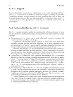
Throughput (Mbps)
Number of logic elements
Fig. 9.18 Logic size for different throughputs
9.5 Conclusion and Perspectives
In this chapter, we presented GAUT [1], which is an academic and open source high-
level synthesis tool dedicated to digital signal processing applications. We described
the different tasks that compose the datapath synthesis flow: compilation, operator
characterization, operation clustering, resource allocation, operation scheduling and
binding. Memory and communication interface synthesis has also been described in
this chapter.
Current work targets the area optimization of the architecture generated by
GAUT through an approach based on iterative refinement. The integration of Con-
trol and Data Flow Graph CDFG model to be used as internal representation is
also in progress. The loop transformations will be addressed during the compilation
step thanks to the features provided by the last versions of the gcc/g++ compiler.
An approach to map data in memories will be proposed to limit the access con-
flicts. Automatic algorithm transformation will be addressed through Taylor Expan-
sion Diagram. Multi-clock domain synthesis is also currently considered. Starting
from an algorithmic specification and design constraints a Globally Asynchronous
Locally Synchronous GALS architecture will be automatically synthesized. This
will allow to design high-performance and low-power architectures.
Acknowledgments Authors would like to acknowledge all the GAUT contributors and
more specifically Caaliph Andriamisaina, Emmanuel Casseau, Gwenol´e Corre, Christophe Jego,
Emmanuel Juin, Bertrand Legal, Ghizlane Lhairech and Kods Trabelsi.
References
1. />2. B. Ramakrishna Rau, “Iterative modulo scheduling: an algorithm for software pipelining
loops”, In Proceedings of the 27th annual international symposium on Microarchitecture,
pp. 63–74, November 30–December 02, 1994, San Jose, CA, United States
9 GAUT: A High-Level Synthesis Tool for DSP Applications 169
3. C. Chavet, C. Andriamisaina, P. Coussy, E. Casseau, E. Juin, P. Urard and E. Martin, “A design
flow dedicated to multi-mode architectures for DSP applications”, In Proceedings of the IEEE
International Conference on Computer Aided Design ICCAD, 2007
4.
5. www.mentor.com
6. www.systemc.org
7.
8. Z. Galil, “Efficient algorithms for finding maximum matching in graphs”, ACM Computing
Survey, Vol. 18, No. 1, pp. 23–38, 1986
9. S. Mahlke, R. Ravindran, M. Schlansker, R. Schreiber and T. Sherwood, “Bitwidth cognizant
architecture synthesis of custom hardware accelerators”, IEEE Transactions on Computer-
Aided Design of Circuits and Systems, Vol. 20, No. 11, pp. 1355–1371, 2001
10. C. Andriamisaina, B. Le Gal and E. Casseau, “Bit-width optimizations for high-level synthesis
of digital signal processing systems”, In SiPS’06, IEEE 2006 Workshop on Signal Processing
Systems, Banff, Canada, October 2006
11. J. Cong, Y. Fan, G. Han, Y. Lin, J. Xu, Z. Zhang and X. Cheng, “Bitwidth-aware schedul-
ing and binding in high-level synthesis”, In Proceedings of ASPDAC, Computer Science
Department, UCLA and Computer Science and Technology Department, Peking University,
2005
12. N. Herve et al., “Data wordlength optimization for FPGA synthesis”, In IEEE Workshop on
Signal Processing Systems Design and Implementation, pp. 623–628, 2005
13. A. Baganne, J L. Philippe and E. Martin, “A formal technique for hardware interface design”,
IEEE Transactions on Circuits and Systems, Vol. 45, No. 5, 1998
14. P. Panda et al., “Data and memory optimization techniques far embedded systems”, Transac-
tions on Design Automation of Electronic Systems, Vol. 6, No. 2, pp. 149–206, 2001
15. F. Catthoor, K. Danckaert, C. Kulkami and T. Omns, “Data Transfer and Storage (DTS)
architecture issues and exploration in multimedia processors”, Marcel Dekker, New York,
2000
16. G. Corre, E. Senn, P. Bornel, N. Julien and E. Martin, “Memory accesses management dur-
ing high level synthesis”, In Proceedings of International Conference on Hardware/Software
Codesign and System Synthesis, CODES+ISSS, 2004, pp. 42–47, 2004
17. P. Bomel, E. Martin and E. Boutillon, “Synchronization processor synthesis for latency insen-
sitive systems”, In Proceedings of the Conference on Design, Automation and Test in Europe,
Vol. 2, pp. 896–897, 2005
18. P. Coussy, E. Casseau, P. Bomel, A. Baganne and E. Martin, “A formal method for hardware
IP design and integration under I/O and timing constraints”, ACM Transactions on Embedded
Computing Systems, Vol. 5, No. 1, pp. 29–53, 2005
19. L. P. Carloni, K. L. McMillan and A. L. Sangiovanni-Vincentelli, “Theory of latency-
insensitive design,” IEEE Transactions on Computer Aided Design of Integrated Circuits and
Systems, Vol. 20, No. 9, p. 18, 2001
20. International Technology Roadmap for Semiconductors ITRS, 2005 editions
21. L. P. Carloni and A. L. Sangiovanni-Vincentelli, “Coping with latency in SoC design,” IEEE
Micro, Special Issue on Systems on Chip, Vol. 22, No. 5, p. 12, 2002
22. M. Singh and M. Theobald, “Generalized latency-insensitive systems for single-clock and
multi-clock architectures,” In Proceedings of the Design Automation and Test in Europe
Conference (DATE’04), Paris, February 2004
23. M. R. Casu and L. Macchiarulo, “A New Approach to Latency Insensitive Design,” In
Proceedings of the Design and Automation Conference (DAC’04), San Diego, June 2004
24. Sundance Mu1ti-Processor Technology,
25. A. J. Viterbi, “Error bounds for convolutional codes and an asymptotically optimum decoding
algorithm”, IEEE Transactions on Information Theory, Vol. IT-13, pp. 260–269, 1967
Chapter 10
User Guided High Level Synthesis
Ivan Aug´eandFr´ed´eric P´etrot
Abstract The User Guided Synthesis approach targets the generation of coproces-
sor under timing and resource constraints. Unlike other approaches that discover
the architecture through a specific interpretation of the source code, this approach
requires that the user guides the synthesis by specifying a draft of its data-path archi-
tecture. By providing this information, the user can get nearly the expected design
in one shot instead of obtaining an acceptable design after an iterative process. Of
course, providing a data-path draft limits its use to circuit designers.
The approach requires three inputs: The first input is the description of the algo-
rithm to be hardwired. It is purely functional, and does not contain any statement or
pragma indicating cycle boundaries. The second input is a draft of the data-path on
which the algorithm is to be executed. The third one is the target frequency of the
generated hardware.
The synthesis method is organized in two main tasks. The first task, called
Coarse Grain Scheduling, targets the generation of a fully functional data-path.
Using the functional input and the draft of the data-path (DDP), that basically is
a directed graph whose nodes are functional or memorization operators and whose
arcs indicate the authorized data-flow among the nodes, this task generates two
outputs:
• The first one is a RT level synthesizable description of the final coprocessor data-
path, by mapping the instructions of the functional description on the DDP.
• The second one is a coarse grain finite state machine in which each operator
takes a constant amount of time to execute. It describes the flow of control with-
out knowledge of the exact timing of the operators, but exhibits the parallelism
among the instruction flow.
The data-path is synthesized, placed and routed with back-end tools. After that, the
timings such as propagation, set-up and hold-times, are extracted and the second
task, called Fine Grain Scheduling, takes place. It basically performs the retiming
of the Coarse Grain finite state machine taking into account the target frequency and
the fine timings of the data-path implementation.
P. Coussy and A. Morawiec (eds.) High-Level Synthesis.
c
Springer Science + Business Media B.V. 2008
171
172 I. Aug´eandF.P´etrot
Compared to the classical High Level Synthesis approaches, the User Guided
Synthesis induces new algorithmic problems. For Coarse Grain Scheduling, it con-
sists of finding whether an arithmetic and logic expression of the algorithmic input
can be mapped on the given draft data-path or not, and when several mappings are
found, to choose the one that maximizes the parallelism and minimizes the added
resources. So the Coarse Grain Scheduling can be seen as a classical compiler, the
differences being firstly that the target instruction set is not hardwired in the com-
piler but described fully or partially in the draft data-path, and secondly that a small
amount of hardware can be added by the tools to optimize speed.
For Fine Grain Scheduling, it consists of reorganizing the finite state machine to
ensure that the data-path commands are synchronized with the execution delays
of the operators they control. The fine grain scheduling also poses interesting
algorithmic problems, both in optimization and in scheduling.
Keywords: Behavioral synthesis, FSM retiming, Design space exploration,
Scheduling, Resource binding, Compilation
10.1 Introduction
10.1.1 Enhanced Y Chart
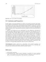
The Y chart representation proposed by Gajski [10] can not accurately represent the
recent synthesis and high level synthesis tools. So we have enhanced it as shown
Fig. 10.1. In the enhanced Y chart, a control flow level is inserted between the sys-
tem and data flow levels. It corresponds to the coprocessor synthesis and allows
to distinguish co-design from high level synthesis. In the structural view, a copro-
cessor is usually a data-path controlled by a FSM. There are two possible types of
description in the behavioral view. The synchronized description is more or less a
Register Transfer Language where cycle boundaries are explicitly set by the lan-
guage. The non-synchronized description is based on imperative languages such as
C, PASCAL, and in this type of description, the cycle boundaries are not given.
As shown in the Fig. 10.1, High Level Synthesis consists of making a structural
description of a circuit from a non-synchronized description of a coprocessor. A
usual approach [6,14, 24] is to generate the synchronized description of the copro-
cessor (plain arrow in Fig. 10.1) and to submit it to a CAD frameworks having an
efficient RTL synthesis tool.
10.1.2 UGH Overview
The multiple arrows noted 1.a,1.b and 1.c on the Fig. 10.2a describe the User
Guided High level synthesis tool (UGH). It starts from a non-synchronized descrip-
tion of an algorithm and generates a structural description of the coprocessor (arrow
10 User Guided High Level Synthesis 173
co−design
High level synthesis
RTL synthesis
data−path synthesis
FSM synthesis
logic synthesis
circuit synthesis
LOGIC
CIRCUIT
transistors
logic cells
transistors
fonctions
cells
processor
algorithm
system
processors
bus, memories
macro−cells
Physical View
Data−Flow
SYSTEM
Levels of behavioral viewLevels of structural view
control FSM
data path,
ALUs, registers,
memories
control FSM
arithmetic data path
boolean data path
Control Flow
synchronized langage
non−synchronized langage
Fig. 10.1 Enhanced Y chart
ALUs, memories,
data path,
FSM
operators
Moore FSM
functional or sequential
description
non−synchronized
Structural view Behavioral view
11.a
1.a
1.b
1.c
ALUs, memories,
data path,
FSM
operators
Moore FSM
functional or sequential
description
description
non−
synchronized
synchronized
Structural view Behavioral view
11.a
1.a
2
1.b
1.c
SGCfotrahcY)bHGUfotrahcY)a
ALUs, memories,
data path,
FSM
operators
Moore FSM
functional or sequential
synchronized
non−
description
Structural view Behavioral view
c) Y chart of FGS
Fig. 10.2 Y charts of UGH tools
174 I. Aug´eandF.P´etrot
Fig. 10.3 User view
C description
Draft Data−Path
frequency
physical circui
t
library
standard cell
library
macro cell
synthesis
tool
UGH
1.a on the Fig. 10.2a) composed of a data-path controlled by a finite state machine.
The data-path consists of an interconnection of macro-cells that are described in
data flow (arrow 1.b). The finite state machine is described behaviorally (arrow 1.c).
For describing a coprocessor, as illustrated on Fig. 10.3, the user inputs of UGH
are the non-synchronized description in C language, the synthesis constraints (Draft
Data Path or DDP) and the target frequency of the coprocessor. UGH produces the
coprocessor circuit running at the given frequency with the help of a logic and FSM
synthesis framework and a standard cell library. The main features of UGH reside in:
Macro-cell library. UGH synthesis process is based on a macro-cell library con-
taining both functional cells such as and, adder, ALU, multiplier, andsequential
ones such as DFF, input/output ports, RAMs, register files, A macro-cell is
generic, the parameters being the bit size and various others ones depending on
its type. For instance, for a DFF a parameter indicates if it has a synchronous reset,
for a RAM parameters indicate whether there is a single address port for read and
write or not.
A macro-cell is a complex object with different views. The functional view
describes the operation, or the operations for multi-operation cells such as ALU
(plus,minus,logicand, )orregister(write,read,set, ),thecellperforms.The
synthesis view is used to generate the synthesizable VHDL description of a specific
instance of the generic macro-cell. The scheduling view is a time modelization of
the macro cell. As opposed to most current High Level Synthesis tools that use a
propagation delay, it accurately and generically describes the timing behavior of the
macro-cell. For the functional macro-cells, these rules are based on the minimum
and maximum propagation times between every output ports and the input ports.
For the sequential macro-cells, the rules are more complex and take into account
propagation, setup and hold times.
Every C operator has at least a macro-cell implementing it, but some specific
macro-cells such as input/output operations or special shift operations (see 10.3.3.1)
can be explicitly invoked using a procedure call in the C description.
Design space exploration. Design space exploration is a crucial problem of high
level synthesis. The HLS tools usually propose an iterative approach to explore
the design space. The user runs the synthesis, the result being the FSM graph and
various cross-reference tables (between states and source statements, between cells
10 User Guided High Level Synthesis 175
andsourcestatements, ).Then,usingpragmainthesourcefile,theusercanforce
“specific” allocations. He runs again the HLS synthesis to get the new results and
so on until he obtains the expected design. This iterative approach is difficult to
use primarily because: (1) For large designs the time between iterations is too long.
(2) The tables are difficult to interpret. The analysis of the results to set judicious
pragmas requires to rebuild the data-path from the cross-reference tables, and this
is a very long and tedious work. (3) This latter work must be done again at each
iteration, because it is not obvious to predict the effect of a change in a pragma. So
the iterative approach is not suited to large designs.
The UGH approach, on the contrary, allows to guide the tool towards the solution
in a single step. It is however only aimed at VLSI designers. The designer does not
have to change his working habits. He provides a data-path and a FSM, the only
difference is that for UGH only a draft of the data-path is needed (see Fig. 10.7
and Sect. 10.3.1) and that the FSM (see Fig. 10.6) is a C program. So designers can
obtain designs very close to the one they would have by RTL flows, but can easily
explore many solutions.
Input frequency. A circuit is most often a piece of a larger system with speci-
fications that determine its running frequency. Most of the HLS tools let the logic
synthesis adapt their RTL outputs to the frequency. This approach neither ensures
that the circuit can be generated (logic synthesis tools may not respect the clock
frequency) nor ensures that the generated circuit is functional at the given clock fre-
quency and even at any frequency if the circuit mixes short and long combinational
paths. Furthermore, this approach generates very large circuits when the logic syn-
thesis tools enter into speculative computation techniques. Taking an opposite view,
UGH adapts the synthesizable description to the given frequency to guarantee that
logic synthesis will be able to produce the circuit and that the circuit will run at the
required frequency.
Input/output. Our point of view is that the synthesis of the communications of
the coprocessor with the external world is not the purpose of the high level synthesis
process. As the imperative languages do, UGH defines input and output primitives
mapped to the macro-cells presented in Fig. 10.4a. These macro-cells implement
Output FIFO
Input FIFO
SROK
SWOK
SDOUTi
SWRITEi
SDINi
SREADi
Processor
SROK
READ
SROK
SWO
K
WRITE
SWOK
weivgniludehcS)btnenopmoC)a
Fig. 10.4 Input/output macro-cells
176 I. Aug´eandF.P´etrot
basic asynchronous communication. From the coprocessor side, the data read action
from a FIFO is shown Fig. 10.4b. In the READ state, the coprocessor asserts the
SREAD signal and loads the SDIN signals’ data into an internal register. If SROK
is not asserted, it means the SDIN signals’ data are not significant and the state
must be run again. Otherwise the value loaded from SDIN is significant, and the
producer pops it. The writing action is similar to the reading action. The read and
write primitives are blocking. As shown Fig.10.4a, if the flow of data is bursty, the
designer can use hardware FIFO to smooth the transfers.
10.2 User Guided HLS Flow
The synthesis process, presented in the Fig. 10.5, is split into three main steps: The
Coarse Grain Scheduling (CGS) generates a data-path and a finite state machine
from the C program and the DDP. This finite state machine does not take the
propagation delays into account. It is more a finite control step machine which
maximizes the parallelism that is possible on the data-path, and we call it CG-
FSM.
Then the mapping is performed. Firstly, the generation of the physical data-path
is delegated to classical back-end tools (logic synthesis, place and route) using a
target cell library. Secondly, the temporal characteristics of the physical data-path
are extracted. At this point, the data-path of the circuit is available.
Finally, the Fine Grain Scheduling (FGS) retimes for the given frequency the
finite control step machine, taking accurately into account the annotated timing
delays of the data-path, and produces the finite state machine of the circuit.
VHDL
Data−Path
Draft
Data−Path
UGH−FGS
Annotations
Timing
Synthesis +
Caracterization
VHDL
Data−Path
Cell
Library
Behavioral
SystemC
subset
accurate
SystemC
Model
Cycle
Depends on the
back−end
synthesis tool
VHDL
CG−FSM
VHDL
FG−FSM
CKUGH−CGS
UGH−MAPPING
Fig. 10.5 User guided high level synthesis flow
10 User Guided High Level Synthesis 177
10.3 Coarse Grain Scheduling
The arrow 1 in the Y chart of the Fig. 10.2b represents CGS. It is similar to the UGH
arrow but the generated circuit is probably not functional.
CGS can also produce a synchronized description functionally and temporally
equivalent to the former (arrow 2 on the Fig. 10.2b). This output is similar to those
generated by usual high level synthesis tools and delegates the main work to a RTL
synthesis tool.
10.3.1 Inputs
The first input (see Fig. 10.6), is the behavior of the coprocessor given as a C pro-
gram. Most C constructs are allowed, but pointers, recursive functions and the use
of standard functions (e.g., printf, strcat, ) is forbidden. Furthermore, all vari-
ables must be either global or static unless their assignments can be inlined in the
statements that read them. The basic C types, char, short, int, long and their
unsigned version are extended with intN and uintN,whereN is an integer in
range 1–128 which defines the bit-size of the type.
The entry point is the ugh_main function. The ugh
inChannelN and
ugh
outChannelN types define communication ports compatible with the hard-
ware FIFO components. The ugh_read and ugh_write functions generate the
state and arcs shown in Fig. 10.4b.
The second input (see Fig. 10.7a) is a simplified structural description of the
target data-path called Draft Data-Path (DDP). The DDP is a directed graph
(Fig. 10.7b) whose nodes are functional or memorization operators and whose arcs
indicate the authorized data-flow between the nodes. For instance, the 2 arcs that
point to the a input of the Subst node indicate that in the final data-path the bits of
this input can be driven by: (a) constants, (b) bits of the q port of the x register, (c)
bits of the q port of the y register, (d) any bit-wise combination of the former cases.
Furthermore, the DDP does not express the bit size of the operators associated to
the nodes, nor the bit size of the arcs. Notice that specifying the arcs is optional as
explained in Sect. 10.3.3.2.
#include <ugh.h>
/* communication channels */
ugh_inChannel32 instream;
ugh_outChannel32 outstream;
/* registers */
uint32 x,y;
/* behavior */
void ugh_main()
{
while (1) {
ugh_read(instream,&x);
ugh_read(instream,&y);
while (x!=y) {
if (x<y) y = y - x ;
else x = x - y ;
}
ugh_read(outstream,&x);
}
}
Fig. 10.6 UGH-C for Euclid’s GCD algorithm
178 I. Aug´eandF.P´etrot
x.d = subst.s, instream;
subst.b = x.q, y.q;
subst.a = x.q, y.q;
outstream = x.q;
SUB subst;
DFF x, y;
{
}
MODEL GCD(IN instream;
OUT outstream)
(a) (c)(b)
y.d = subst.s, instream;
instream
z
i0
i1
d
i1
i0
qdz
i0
i1
z
i1
i0
a
s
b
z
qz
co
M2
M1
M3
M4
subst
sel_m1
we_ra sel_m4
inf
zero
sel_m3we_rbsel_m2ck
din
y
x
dout
s
y
qd
x
d
q
subst
z
co
a
b
outstream
Fig. 10.7 Draft Data-Path of the GCD example
The C input and the DDP are interdependent. A global or static variable (respec-
tively: array) of the C input must correspond to a register (respectively: register file
or static RAM) of the DDP having the same name. For each statement of the C
input there must be at least a sub-graph of the directed graph that can execute the
statement.
10.3.2 CGS Overview
The Coarse Grain Scheduling uses the C input and the draft data-path to produce
firstly the circuit data-path and secondly a coarse grain finite state machine (CG-
FSM).
CGS starts with a consistency check. Enough registers must have been instanti-
ated to store all the non-trivial variables. Each statement of the C description must
correspond to at least one sub-graph of the DDP.
Then the binding takes place: Each node of the DDP corresponds to a macro-cell
of the data-path. Its bit size is deduced from the bit size of the C variables, the input
connectors of the cells are connected to output connectors either directly or using a
multiplexer when inputs are driven by different sources. The resulting data-path of
the GCD example is shown in Fig. 10.7c.
Finally the CG-FSM is elaborated, where coarse grain means that the operations
are only partially ordered like in soft scheduling [26]. This FSM is built using the
following timing constraints: multipliers need 2 cycles, adders and subtracters need
1 cycle, and all other functional cells have negligible propagation times.
10.3.3 Features and Algorithms
10.3.3.1 C Synthesis Rules
The Table 10.1 summarizes the computation of the size of the physical operators
bound to a C operator. A C operator is used either in an assignment, such as