ADOBE INDESIGN CS2 REVEALED- P19 ppt
Bạn đang xem bản rút gọn của tài liệu. Xem và tải ngay bản đầy đủ của tài liệu tại đây (600.11 KB, 15 trang )
INDESIGN 7-12 Creating Graphics
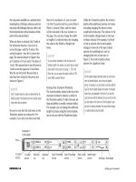
FIGURE 14
Viewing the results of altering the path with the Convert Direction Point Tool
4. Click the Convert Direction Point Tool ,
then drag the direction line from point 9 to
position the path properly between points 9
and 10.
As shown in Figure 14, the Convert Direction
Point Tool allows you to alter the path
between points 9 and 10 without affecting
the path between points 8 and 9.
5. Click the Pen Tool , click point 10 to
reconnect to the path, then click point 11.
6. Position the Pen Tool pointer over point 12,
then click and drag a direction line to the
yellow star above and slightly to the left of it.
The direction line does not point toward the
next point—point 13.
7. Click point 12 with the Pen Tool pointer.
Clicking a point with the Pen Tool pointer
removes the direction line.
8. Position the Pen Tool pointer over point 13, then
click and drag a direction line to the yellow star.
(continued)
Lesson 1 Use the Pen Tool INDESIGN 7-13
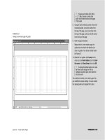
FIGURE 15
Viewing the finished drawing
9. Position the Pen Tool pointer over point 14,
then click and drag a direction line to the
yellow star.
10.Using the same skills used in Steps 6
through 9, create points 15 through 18.
11.Click the starting anchor point (on the pur-
ple star) to close the path.
12.Click the Swap Fill and Stroke button in
the Toolbox, fit the page in the window, then
hide Layer 1 in the Layers palette.
13.Save your work, compare your page to
Figure 15, then close Halloween Witch.
You finished drawing a closed path. You used the
Convert Direction Point Tool to change direction
while drawing.
LESSON 2
What You’ll Do
INDESIGN 7-14 Creating Graphics
Reshaping Frames
The Toolbox offers a number of tools for
creating basic shapes. The graphics frame
tools include the Rectangle, Polygon, and
Ellipse; you can also use the regular
Rectangle, Polygon, and Ellipse tools. The
objects that you create with any of these
tools can be modified using the Direct
Selection Tool or the Pen Tool.
When you select an object, the appearance
of the object will differ depending on
which of the two selection tools is selected
in the Toolbox. Figure 16 shows the
appearance of the same object when the
Selection Tool and the Direct Selection
Tool are active in the Toolbox.
When the Selection Tool is selected, you’ll
see the object’s bounding box. The bound-
ing box includes eight handles, which you
can manipulate to change the object’s size.
When you click the Direct Selection Tool,
the object’s bounding box disappears and is
replaced by its path. You can select and
move anchor points or path segments along
the path. Figure 17 shows a rectangle
In this lesson, you will use the Pen Tool to
reshape frames and create stroke effects,
including dashed line patterns.
▼
RESHAPE FRAMES AND
APPLY STROKE EFFECTS
Using the rectangle tools
The Toolbox contains two tools for creating rectangles: the Rectangle Frame Tool and
the Rectangle Tool. What is the difference, you may ask? The surprising answer is
that there really is no difference. Both create rectangular shaped objects. Both can be
filled and stroked with color. Both can contain a placed graphic. About the only dis-
tinction between the two is that the Rectangle Frame Tool is considered one of the
graphics frames tools and is used for placing graphics in, whereas the Rectangle Tool
creates rectangles that are meant to be used as simple illustrations. However, as
stated above, both can be filled and stroked, and both can contain placed graphics.
FIGURE 17
A reshaped rectangle
FIGURE 18
A reshaped rectangle with the Selection Tool activated
FIGURE 19
A rectangle reshaped with three added anchor points
Lesson 2 Reshape Frames and Apply Stroke Effects INDESIGN 7-15
reshaped by using the Direct Selection Tool.
Figure 18 shows that, when the Selection
Tool is activated, the reshaped object is once
again positioned within its bounding box.
When an object is selected, clicking the Pen
Tool has the same effect as clicking the
Direct Selection Tool—the eight handles
disappear and are replaced by anchor points.
Just as with any other path, you can use the
Pen Tool to add or delete anchor points to
give you further control for reshaping an
object. Figure 19 shows the same object
reshaped with three added anchor points.
Remember, when the Direct Selection Tool
or the Pen Tool is active in the Toolbox, any
selected object is essentially a path, com-
posed of anchor points and path segments,
and able to be manipulated like any other
path. This means that, using the Direct
Selection Tool or the Pen Tool, the basic
objects that you create with the shape
tools—rectangles, ellipses, and polygons—
can be reshaped into anything that your
imagination can dream up!
FIGURE 16
Viewing a selected object
Bounding
box handles
Anchor
points
Appearance of
selected object
when Selection
Tool is active
Appearance of
selected object
when Direct
Selection Tool is
active
Anchor points
may be moved
independently
Bounding box
Three
added
anchor
points
Center point
Using the new Convert Shape command
Once you create a frame, you are always free to change its basic shape using the
Convert Shape command, which is new to InDesign CS2. For example, if you create a
circular frame and want to change it to a rectangular frame, there’s no need to delete
the circular frame and redraw a rectangle. Instead, simply select the circular frame, go
to the Object menu, then use the Convert Shape menu item to select the Rectangle
command. The new rectangle will appear in the same position on the page that the
circle occupied. Experiment with this cool new feature—it can come in very handy.
INDESIGN 7-16 Creating Graphics
Defining Strokes
Color that you apply to a path is called a
stroke. Once you’ve applied a stroke to a
path, you can manipulate characteristics of
the stroke using the Stroke palette. There,
you can adjust the weight or thickness of
the stroke. You have options for changing
the design of the stroke, such as making it
a dotted line instead of a solid line. You can
format the stroke as a dashed stroke, and
you can apply end shapes to the stroke,
such as arrowheads and tail feathers.
Defining Joins and Caps
Once you’ve applied a stroke to a path, you
should decide upon joins and caps for the
path. Make a note of this, because your
choice for joins and caps can have a subtle
but effective impact on your illustration.
However, these are attributes that many
designers forget about or just plain
ignore—to the detriment of their work.
Joins define the appearance of a corner
point when a path has a stroke applied to
it. There are three types of joins: miter,
round, and bevel. The miter join, which
produces pointed corners, is the default.
The round join produces rounded corners,
and the bevel join produces squared cor-
ners. Figure 20 shows examples of all three
joins.
Sometimes, it is hard to see which type of
join is being used. The greater the weight
of the stroke, the more apparent the join
will be.
Caps define the appearance of end points
when a stroke is added to a path. The
Stroke palette offers three types of caps:
butt, round, and projecting. Butt caps
produce squared ends and round caps pro-
duce rounded ends. Generally, round caps
are more appealing to the eye. The pro-
jecting cap applies a squared edge that
extends the anchor point at a distance
that is one-half the weight of the stroke.
With a projecting cap, the weight of the
stroke is equal in all directions around the
line. The projecting cap is useful when
you align two anchor points at a right
angle, as shown in Figure 21.
Joins and caps are subtle features, but they
are effective. Note the different appear-
ances of the three heads in Figure 22. Note
the round caps vs. the bluntness of the butt
caps, especially visible on the character’s
nose. Note, too, the corners of the charac-
ter’s mouth, which are sharp with miter
joins, rounded with round joins, and blunt
with bevel joins.
FIGURE 20
Three types of joins
FIGURE 21
Viewing projecting caps
FIGURE 22
Viewing different effects with different joins and caps
Miter join
Round join
Bevel join
Anchor
points align
Stroke "projects"
beyond anchor
point
Strokes
"project" to
create right
angle
Miter join
Round join
Bevel join
Butt cap
Round cap
Lesson 2 Reshape Frames and Apply Stroke Effects INDESIGN 7-17
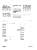
Defining the Miter Limit
The miter limit determines when a miter
join will be squared off to a beveled edge.
The miter is the length of the point, from
the inside to the outside, as shown in
Figure 23. The length of the miter is not
the same as the stroke weight. When two
stroked paths are at an acute angle, the
length of the miter will greatly exceed the
weight of the stroke, which results in an
extreme point that can be very distracting.
The default miter limit is 4, which means
that when the length of the miter reaches
4 times the stroke weight, it will automati-
cally be squared off to a beveled edge.
Generally, you will find the default miter
limit satisfactory, but be conscious of it
when you draw objects with acute angles,
such as stars or triangles.
Creating a Dashed Stroke
Dashed strokes, which are created and
formatted using the Stroke palette, are
strokes that consist of a series of dashes
and gaps. You define the dash sequence for
a dashed stroke by entering the lengths of
the dashes and the gaps between them in
the dash and gap text boxes in the Stroke
palette. You can create a maximum of three
different sized dashes separated by three
different sized gaps. The pattern you estab-
lish will be repeated across the length of
the stroke. Figure 24 shows a dashed
stroke and its formatting in the Stroke
palette.
FIGURE 23
Understanding miters and miter limits
FIGURE 24
Formatting a dashed stroke
Dashes
have
butt
caps
12 pt
gaps
24 pt
dash
6 pt
dash
Point reduced to
a beveled edge
Measurement
of miter
INDESIGN 7-18 Creating Graphics
Reshape a frame using the
Direct Selection Tool and
Pen Tool
1. Open ID 7-2.indd, then save it as Halloween
Invitation.
2. Click the Selection Tool , click the
Orange Clouds.tif graphic, copy it, click Edit
on the menu bar, then click Paste in Place.
A duplicate frame and graphic is placed
directly in front of the original.
3. Place Blue clouds.tif, from the location
where your Chapter 7 Data Files are stored,
in the new frame.
4. Click the Direct Selection Tool .
5. Drag the top-right corner point toward the
center so that it is in approximately the loca-
tion shown in Figure 25.
6. Click Edit on the menu bar, then click
Undo Move.
7. Click the Pen Tool , then add an anchor
point on the top path of the frame, where it
intersects with the burgundy guide.
8. Add an anchor point on the right path of
the frame, where it intersects with the
burgundy guide.
Your page should resemble Figure 26.
9. Position the Pen Tool pointer over the top-
right corner point.
The Pen Tool pointer becomes the Delete
Anchor Point Tool .
10.Click the top-right corner point to delete it.
Your screen should resemble Figure 27.
You used the Pen Tool to reshape a graphics frame.
FIGURE 25
Moving the top-right corner point independently
FIGURE 26
Viewing two added anchor points
FIGURE 27
Viewing the results of deleting an anchor point
Added anchor points
Lesson 2 Reshape Frames and Apply Stroke Effects INDESIGN 7-19
FIGURE 28
Creating a rectangle
FIGURE 29
Viewing the results of deleting the added anchor point
FIGURE 30
Viewing the path
Path positioned
on margin guides
Clicking the Default
Fill and Stroke
button changes the
stroke color to black
End point
End point
Reshape a frame into an
open path
1. Verify that None is selected for both the fill
and stroke colors in the Toolbox, click the
Rectangle Tool , then create a rectangle
that snaps to the inside of the four margin
guides, as shown in Figure 28.
2. Click the Pen Tool , then add an anchor
point anywhere on the left segment of
the frame.
3. With the new anchor point still selected,
click Edit on the menu bar, then click Cut.
As shown in Figure 29, when the anchor
point is cut, the two segments connected to
it are also deleted.
4. Click the Default Fill and Stroke button
in the Toolbox.
5. Click Window on the menu bar, then click
Stroke.
6. Click the Weight list arrow in the Stroke
palette, then click 4 pt.
7. Place the Pen Tool pointer on the top path of
the frame, where it intersects with the blue
guide; then, when it changes automatically
to the Add Anchor Point Tool pointer, click to
add an anchor point.
8. Add an anchor point on the right path of
the frame, where it intersects with the
blue guide.
9. Click the Delete Anchor Point Tool , then
click the top-right anchor point.
Your screen should resemble Figure 30.
You created a simple rectangle, then reshaped it
into an open path.
INDESIGN 7-20 Creating Graphics
Use the Stroke palette to add
end shapes to a path
1. Click the Preview Mode button in the
Toolbox, click the Selection Tool , then
click the black-stroked path.
TIP All objects, even open paths, are
selected within a rectangular bounding box.
2. Click the Start list arrow in the Stroke
palette, then click CircleSolid.
TIP Click the Stroke palette list arrow, then
click Show Options, if necessary.
3. Click the End list arrow, click CircleSolid,
then compare your page to Figure 31.
4. Click the Normal View Mode button ,
click the Pen Tool , then position
it over the location where the diagonal sec-
tion of the black path intersects with the yel-
low guide.
5. When you see the Pen Tool pointer change to
the Add Anchor Point Tool pointer , click.
6. Add another anchor point where the black path
intersects with the horizontal burgundy guide.
7. Add a third new anchor point approximately
halfway between the two new anchor points.
8. Deselect all, click the Direct Selection Tool ,
select only the anchor point you added in Step 7,
click Edit on the menu bar, then click Cut.
Your page should resemble Figure 32.
9. Deselect all, click the Selection Tool ,
click the top black path, click the Pen Tool
, float the pointer over the anchor point
where the top black path intersects with the
yellow guide, then stop when a diagonal line
appears beside the Pen Tool pointer.
(continued)
FIGURE 31
Viewing end shapes
FIGURE 32
Viewing end shapes on two paths
CircleSolid
end shapes
Lesson 2 Reshape Frames and Apply Stroke Effects INDESIGN 7-21
FIGURE 33
Adding a triangle end shape to an extended path
FIGURE 34
Formatting a dashed stroke
FIGURE 35
Viewing dashed strokes
Path extended
down with triangle
end shape applied
Round caps
on dashes
The diagonal line indicates that the Pen Tool
is being used to reconnect to the path.
10.Click the Pen Tool pointer on the anchor
point, press and hold [Shift], then click where
the yellow guide intersects with the blue guide.
11.In the Stroke palette, click the Start list
arrow, then click Triangle.
Your page should resemble Figure 33.
12.Click the Selection Tool , select the bot-
tom black path, click the End list arrow, then
click Triangle.
You added end shapes to a path, split the path,
then noted that the end shapes were applied to the
two new paths.
Create a dashed stroke
1. Click View on the menu bar, point to Grids
and Guides, then click Hide Guides.
2. Click the Selection Tool if necessary,
then select both black paths.
3. Click the Type list arrow in the Stroke
palette, then click Dashed.
4. Type 14, 8, 3, and 8 in the dash and gap text
boxes in the Stroke palette, as shown in
Figure 34.
5. Click the Round Cap button in the
Stroke palette, deselect all, then compare
your page to Figure 35.
You used the Stroke palette to format a path with a
dashed stroke using round caps.
Dash and
gap sizes
LESSON 3
What You’ll Do
INDESIGN 7-22 Creating Graphics
Creating Polygons
The Toolbox offers the Polygon Tool and
the Polygon Frame Tool for creating multi-
sided objects, such as triangles, pentagons,
hexagons, etc. You can place graphics into
objects you create with either tool.
To determine how many sides you want
your polygon to be, double-click the tool to
open the Polygon Settings dialog box, as
shown in Figure 36. If, for example, you
enter 5 in the Number of Sides text box and
then click OK, when you click and drag with
the Polygon Tool selected, you will create a
pentagon. Press and hold [Shift] when drag-
ging to create a perfect pentagon with all
5 sides of equal length.
The Star Inset setting allows you to use the
Polygon Tool or the Polygon Frame Tool to
create star shapes. The greater the Star
Inset percentage, the more acute and longer
the points of the star will be, as shown in
Figure 37. The number entered in the
Number of Sides text box determines the
number of points on the star.
Creating Compound Paths
Imagine you were going to use the Pen Tool
to trace the outline of a doughnut. You
would draw an outer circle for the doughnut
itself, then an inner circle to define the
doughnut hole. Then, you would want to
format the two paths so that the inner
circle “cuts a hole” in the outer circle.
In this lesson, you will work with polygons
and use them to create compound paths
and anchored objects.
▼
FIGURE 36
Polygon Settings dialog box
FIGURE 37
Comparing different star inset percentages
40% star inset
70% star inset
WORK WITH POLYGONS
AND COMPOUND PATHS
Lesson 3 Work with Polygons and Compound Paths INDESIGN 7-23
You create compound paths when you want
to use one object to cut a hole in another
object. In the above example, you would select
both circles and then apply the Compound
Path command. Figure 38 shows an example
of the result. Note that you can see the blue
square through the hole in the gold circle.
Once compounded, the two paths create
one object.
Compound paths are not only used for the
practical purpose of creating a hole. When you
work with odd or overlapping shapes, the
Compound Path command can produce results
that are visually interesting and can be used as
design elements, as shown in Figure 39.
Using Polygons as Anchored
Objects
Anchored objects are objects that you
create and use as text characters within a
block of text. Figure 40 shows a red star
used as an anchored object to make a block
of text appear more eye-catching.
Anchored objects, called inline frames in
Indesign CS, flow with the text as though it
were a text character. For example, when you
edit the text, the anchored object will flow
forward or backward with the rest of the text.
Anchored objects can be used for practical
purposes. For example, if you were design-
ing a form that required check boxes, you
could create a simple rectangle and then
use it as an anchored object wherever you
needed a check box to appear.
FIGURE 38
Identifying two paths compounded as a single path
FIGURE 39
Using compound paths to design interesting graphics
FIGURE 40
Viewing anchored objects
“Hole” in the circle
Two paths that make
up a compound path
Anchored object
A “hole” is created where
the letter overlaps the circle
INDESIGN 7-24 Creating Graphics
Create polygons, circles,
and lines
1. In the Toolbox, set the fill color to black and
the stroke color to None, then double-click
the Polygon Tool in the Toolbox.
TIP The Polygon Tool may be hidden beneath
the Rectangle Tool, or the Ellipse Tool.
2. Type 8 in the Number of Sides text box, type
70 in the Star Inset text box, then click OK.
3. Drag anywhere on the page to create a poly-
gon of any size.
4. In the Transform palette, verify that the cen-
ter reference point on the proxy is selected,
type 1.25 in both the Width and Height text
boxes, press [Enter] (Win) or [return] (Mac),
then position the polygon in the top-right
corner of the page, as shown in Figure 41.
5. Deselect the polygon, change the fill color in
the Toolbox to yellow, click the Ellipse Tool
, then position the pointer at the center
of the black star polygon.
6. Press and hold [Shift][Alt] (Win) or
[Shift][option] (Mac), then drag a circle
approximately the size shown in Figure 42.
TIP Pressing and holding [Alt] (Win) or
[option] (Mac) allows you to draw a circle
from its center. Pressing and holding [Shift]
constrains the shape to a perfect circle.
7. Click the Selection Tool , click the
pasteboard to deselect all, click the Swap
Fill & Stroke button in the Toolbox,
click the Stroke button to activate it, then
change the weight in the Stroke palette to
4 pt and the type to Solid.
(continued)
FIGURE 41
Positioning the polygon
FIGURE 42
Drawing the circle
Lesson 3 Work with Polygons and Compound Paths INDESIGN 7-25
FIGURE 43
Drawing the line
FIGURE 44
Positioning the witch polygon
FIGURE 45
Viewing the witch polygon with the placed graphic and black stroke
Diagonal line
8. Click the Line Tool , position the pointer
on the top edge of the page where the
orange clouds graphic meets the blue
clouds graphic, then drag a diagonal line
along the base of the orange clouds triangle,
as shown in Figure 43.
You created an eight-pointed polygon, a circle, and
a line.
Place graphics in polygons
1. Open the Halloween Witch file that you cre-
ated, select the witch graphic, copy it, click
Window on the menu bar, click Halloween
Invitation.indd, click Edit on the menu bar,
then click Paste.
2. Position the witch polygon in the location
shown in Figure 44.
Don’t deselect the witch polygon.
3. Click File on the menu bar, click Place, navi-
gate to the drive and folder where your
Chapter 7 Data Files are stored, then double-
click Orange Clouds.tif.
4. Click the Swap Fill & Stroke button in
the Toolbox, change the stroke weight to
2 pt, then deselect.
Your page should resemble Figure 45.
5. Select the star polygon, then place the Blue
clouds.tif graphic in it.
TIP When you place a graphic into a poly-
gon that has a fill, the fill remains, even
though it may not be visible because of the
placed graphic.
6. Click Object on the menu bar, point to
Fitting, then click Fit Content to Frame.
(continued)
INDESIGN 7-26 Creating Graphics
FIGURE 46
Viewing two graphics placed in polygons
FIGURE 47
Positioning the “eye” polygon
FIGURE 48
Creating a compound path
FIGURE 49
Viewing two compound paths
Orange Clouds.tif placed
into “witch” polygon
Blue clouds.tif
placed into the
star polygon
“Eye” polygon
“Eye” polygon
creates a hole in
the “witch”
polygon when
compounded
Compound path
Compound path
7. Change the fill color of the star polygon to
None, deselect, then compare your page to
Figure 46.
8. Select the small ten-pointed polygon in the
pasteboard, then place Orange Clouds.tif
into it.
9. Click Object on the menu bar, point to
Fitting, then click Fit Content to Frame.
You placed three graphics into three polygons.
Create compound paths
1. Click the Selection Tool , select the yel-
low “eye” polygon on the pasteboard, click
Object on the menu bar, point to Arrange,
then click Bring to Front.
2. Position the eye on top of the witch polygon
as shown in Figure 47.
3. Verify that the eye polygon is still selected,
press [Shift], then click the witch polygon
so that both polygons are selected.
4. Click Object on the menu bar, point to
Compound Paths, then click Make.
As shown in Figure 48, the eye polygon
becomes a “hole” in the witch polygon
through which you can see the Blue
clouds.tif graphic.
5. Select both the yellow circle and the star
polygons in the top-right corner of the page.
6. Click Object on the menu bar, point to
Compound Paths, click Make, then
deselect all.
Your page should resemble Figure 49.
You created two compound paths.