Real-Time Embedded Multithreading Using ThreadX and MIPS- P3 docx
Bạn đang xem bản rút gọn của tài liệu. Xem và tải ngay bản đầy đủ của tài liệu tại đây (179.14 KB, 20 trang )
36 Chapter 4
The total number of memory blocks in a memory block pool can be calculated as follows:
Total Number of Blocks
Total Number of Bytes Available
Number of By
ϭ
(
ttes in Each Memory Block sizeof void)( ( *))ϩ
Each memory block contains one pointer of overhead that is invisible to the user and is
represented by the sizeof (void*) expression in the preceding formula. Avoid wasting
memory space by correctly computing the total number of bytes to allocate, based on the
number of desired memory blocks.
4.6 Application Timer
Fast response to asynchronous external events is the most important function of real-time,
embedded applications. However, many of these applications must also perform certain
activities at predetermined intervals of time. Application timers enable applications to execute
application C functions at specifi c intervals of time. It is also possible for an application timer
to expire only once. This type of timer is called a one-shot timer, while repeating interval
timers are called periodic timers . Each application timer is a public resource.
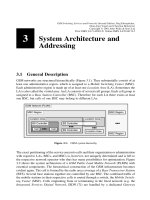
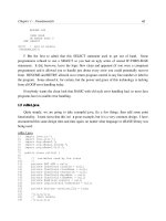
Figure 4.9 contains the attributes of an application timer. Every application timer must
have a Control Block that contains essential system information. Every application timer
is assigned a name, which is used primarily for identifi cation purposes. Other attributes
include the name of the expiration function that is executed when the timer expires.
Another attribute is a value that is passed to the expiration function. (This value is for
www.newnespress.com
Memory block pool control block
Memory block pool name
Number of bytes in each memory block
Location of memory block pool
Total number of bytes available
Figure 4.8 : Attributes of a memory block pool
Please purchase PDF Split-Merge on www.verypdf.com to remove this watermark.
RTOS Building Blocks for System Development 37
www.newnespress.com
the use of the developer.) An attribute containing the initial number of timer-ticks
1
for
the timer expiration is required, as is an attribute specifying the number of timer-ticks
for all timer expirations after the fi rst. The last attribute is used to specify whether the
application timer is automatically activated at creation, or whether it is created in a
nonactive state that would require a thread to start it.
Application timers are very similar to ISRs, except the actual hardware implementation
(usually a single periodic hardware interrupt is used) is hidden from the application.
Such timers are used by applications to perform time-outs, periodic operations, and/
or watchdog services. Just like ISRs, application timers most often interrupt thread
execution. Unlike ISRs, however, application timers cannot interrupt each other.
4.7 Mutex
The sole purpose of a mutex is to provide mutual exclusion; the name of this concept
provides the derivation of the name mutex (i.e., MUTual EXclusion).
2
A mutex is used
Application timer control block
Application timer name
Expiration function to call
Expiration input value to pass to function
Initial number of timer-ticks
Reschedule number of timer-ticks
Automatic activate option
Figure 4.9: Attributes of an application timer
1
The actual time between timer-ticks is specifi ed by the application, but 10 ms is the value used here.
2
In the 1960s, Edsger Dijkstra proposed the concept of a mutual exclusion semaphore with two
operations: the P operation (Prolaag, meaning to lower) and the V operation (Verhogen, meaning
to raise). The P operation decrements the semaphore if its value is greater than zero, and the V
operation increments the semaphore value. P and V are atomic operations.
Please purchase PDF Split-Merge on www.verypdf.com to remove this watermark.
38 Chapter 4
to control the access of threads to critical section or certain application resources. A
mutex is a public resource that can be owned by one thread only. There is no limit on the
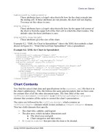
number of mutexes that can be defi ned. Figure 4.10 contains a summary of the attributes
of a mutex.
Every mutex must have a Control Block that contains important system information.
Every mutex is assigned a name, which is used primarily for identifi cation purposes.
The third attribute indicates whether this mutex supports priority inheritance. Priority
inheritance allows a lower-priority thread to temporarily assume the priority of a
higher-priority thread that is waiting for a mutex owned by the lower-priority thread.
This capability helps the application to avoid nondeterministic priority inversion by
eliminating preemption of intermediate thread priorities. The mutex is the only ThreadX
resource that supports priority inheritance.
4.8 Counting Semaphore
A counting semaphore is a public resource. There is no concept of ownership of
semaphores, as is the case with mutexes. The primary purposes of a counting semaphore
are event notifi cation, thread synchronization, and mutual exclusion.
3
ThreadX
provides 32-bit counting semaphores where the count must be in the range from 0 to
4,294,967,295 or 2
32
– 1 (inclusive). When a counting semaphore is created, the count
must be initialized to a value in that range. Each value in the semaphore is an instance of
that semaphore. Thus, if the semaphore count is fi ve, then there are fi ve instances of that
semaphore.
www.newnespress.com
Mutex control block
Mutex name
Priority inheritance option
Figure 4.10: Attributes of a mutex
3
In this instance, mutual exclusion is normally achieved with the use of a binary semaphore, which
is a special case of a counting semaphore where the count is restricted to the values zero and one.
Please purchase PDF Split-Merge on www.verypdf.com to remove this watermark.
RTOS Building Blocks for System Development 39
www.newnespress.com
Figure 4.11 contains the attributes of a counting semaphore. Every counting semaphore
must have a Control Block that contains essential system information. Every counting
semaphore is assigned a name, which is used primarily for identifi cation purposes. Every
counting semaphore must have a Semaphore Count that indicates the number of instances
available. As noted above, the value of the count must be in the range from 0x00000000
to 0xFFFFFFFF (inclusive). A counting semaphore can be created either during
initialization or during run-time by a thread. There is no limit to the number of counting
semaphores that can be created.
4.9 Event Flags Group
An event fl ags group is a public resource. Event fl ags provide a powerful tool for thread
synchronization. Each event fl ag is represented by a single bit, and event fl ags are
arranged in groups of 32. When an event fl ags group is created, all the event fl ags are
initialized to zero.
Figure 4.12 contains the attributes of an event fl ags group. Every event fl ags group must
have a Control Block that contains essential system information. Every event fl ags group
is assigned a name, which is used primarily for identifi cation purposes. There must also
be a group of 32 one-bit event fl ags, which is located in the Control Block.
Event flags group control block
Event flags group name
Group of 32 one-bit event flags
Figure 4.12 : Attributes of an event fl ags group
Counting semaphore control block
Counting semaphore name
Semaphore count
Figure 4.11: Attributes of a counting semaphore
Please purchase PDF Split-Merge on www.verypdf.com to remove this watermark.
40 Chapter 4
Event fl ags provide a powerful tool for thread synchronization. Threads can operate on all 32
event fl ags at the same time. An event fl ags group can be created either during initialization or
during run-time by a thread. Figure 4.13 contains an illustration of an event fl ags group after it
has been initialized. There is no limit to the number of event fl ags groups that can be created.
4.10 Message Queue
A message queue is a public resource. Message queues are the primary means of
interthread communication. One or more messages can reside in a message queue. A
message queue that holds a single message is commonly called a mailbox . Messages are
placed at the rear of the queue,
4
and are removed from the front of the queue.
Figure 4.14 contains the attributes of a message queue. Every message queue must have a
Control Block that contains essential system information. Every message queue is assigned
a name, which is used primarily for identifi cation purposes. Other attributes include the
message size, the address where the message queue is located, and the total number of
bytes allocated to the message queue. If the total number of bytes allocated to the message
queue is not evenly divisible by the message size, then the remaining bytes are not used.
Figure 4.15 contains an illustration of a message queue. Any thread may insert a message
in the queue (if space is available) and any thread may remove a message from a queue.
www.newnespress.com
Message queue control block
Message queue name
Size of each message
Location of message queue
Total size of the message queue
Figure 4.14 : Attributes of a message queue
0
313029282726252423222120191817161514131211109876543210
00000
0
0000000000000000000000000
Figure 4.13: An event fl ags group
4
It is also possible to insert a message at the front of the queue.
Please purchase PDF Split-Merge on www.verypdf.com to remove this watermark.
RTOS Building Blocks for System Development 41
www.newnespress.com
Messages inserted at rear of queue
Messages removed from front of queue
message_n message_3 message_2 message_1
Figure 4.15: A message queue
Mutex Counting semaphore
Speed
Somewhat slower than a
semaphore
A semaphore is generally faster
than a mutex and requires fewer
system resources
Thread ownership
Only one thread can own a
mutex
No concept of thread ownership for
a semaphore – any thread can
decrement a counting semaphore if
its current count exceeds zero
Priority
inheritance
Available only with a mutex
Feature not available for
semaphores
Mutual exclusion
Primary purpose of a mutex – a
mutex should be used only for
mutual exclusion
Can be accomplished with the use
of a binary semaphore, but there
may be pitfalls
Inter-thread
synchronization
Do not use a mutex for this
purpose
Can be performed with a
semaphore, but an event flags
group should be considered also
Event notification
Do not use a mutex for this
purpose
Can be performed with a
semaphore
Thread
suspension
Thread can suspend if another
thread already owns the mutex
(depends on value of wait
option)
Thread can suspend if the value of
a counting semaphore is zero
(depends on value of wait option)
Figure 4.16: Comparison of a mutex with a counting semaphore
4.11 Summary of Thread Synchronization and
Communication Components
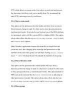
Similarities exist between a mutex and a counting semaphore, especially when
implementing mutual exclusion. In particular, a binary semaphore has many of the same
properties as that of a mutex. Figure 4.16 contains a comparison of these two resources
and recommendations as to how each should be used.
Please purchase PDF Split-Merge on www.verypdf.com to remove this watermark.
42 Chapter 4
application timer mutex ownership
binary semaphore mutual exclusion
Control Block one-shot timer
counting semaphore periodic timer
defragmentation preemption
entry function preemption-threshold
event fl ags group primitive data type
event notifi cation priority
fi rst-fi t allocation priority inheritance
fragmentation public resource
heap service call
ISR stack
mailbox system data type
memory block pool thread
memory byte pool thread suspension
message queue thread synchronization
mutex watchdog timer
We discussed four public resources that a thread can use for various purposes, as well as
four types of situations where each can be useful. Figure 4.17 contains a summary of the
recommended uses of these resources.
4.12 Key Terms and Phrases
www.newnespress.com
Thread
synchronization
Event
notification
Mutual
exclusion
Inter-Thread
communication
Mutex Preferred
Counting
semaphore
OK – better for
one event
Preferred OK
Event flags
group
Preferred OK
Message
queue
OK OK Preferred
Figure 4.17: Recommended uses of resources
Please purchase PDF Split-Merge on www.verypdf.com to remove this watermark.
RTOS Building Blocks for System Development 43
www.newnespress.com
4.13 Problems
1. Explain why the special primitive data types UINT, ULONG, VOID, and CHAR are
used for service calls, rather than the standard C primitive data types.
2. What is the purpose of the thread entry function?
3. Under what circumstances would you use a binary semaphore rather than a mutex for
mutual exclusion?
4. There is only one public resource that can be owned by a thread. Which resource is
that?
5. Suppose you have a choice in using either a memory byte pool or a memory block
pool. Which should you choose? Justify your answer.
6. What does it mean to get an instance of a counting semaphore?
7. What is the maximum number of numeric combinations that can be represented by an
event fl ags group?
8. Messages are usually added to the rear of a message queue. Why would you want to
add a message to the front of a message queue?
9. Discuss the differences between a one-shot timer and a periodic timer.
10. What is a timer-tick?
Please purchase PDF Split-Merge on www.verypdf.com to remove this watermark.
www.newnespress.com
Introduction to the MIPS
Microprocessor
CHAPTER 5
5.1 Introduction
The MIPS microprocessor is one of the world’s most popular processors for embedded
applications. It can be found in applications ranging from hard disk controllers to laser-jet
printers to gaming consoles. The simplicity of the MIPS design is an important reason for
its success. A simpler processor is easier to use and frequently has faster performance.
Because of such features, MIPS is used in many modern products, including the
following:
set-top boxes disk drives
PDAs medical devices
digital cameras automobile navigation systems
ink and laser printers smart cards
switches and routers modems
wireless devices game consoles
5.2 History
The MIPS processor ancestry dates back to the pioneering days of RISC ( reduced
instruction set computer ) development in the early 1980s by John L. Hennessy of
Stanford University. Originally, the MIPS acronym stood for Microprocessor without
Interlocked Pipeline Stages , but the name is no longer considered an acronym today.
1
1
Depending on the specifi c processor, MIPS uses a three-stage, a fi ve-stage, or a six-stage
instruction pipeline. Branch instructions fl ush and refi ll the pipeline.
Please purchase PDF Split-Merge on www.verypdf.com to remove this watermark.
46 Chapter 5
www.newnespress.com
In 1984 Hennessy left Stanford and formed MIPS Computer Systems,
2
which focused on
the MIPS architecture. The fi rst MIPS processor was called the R2000 and was released
in 1985. In 1988, the R3000 was introduced and then the R4000 in 1991. The R4000
was the fi rst 64-bit MIPS microprocessor. The 1990s through the early 2000s also saw
the introduction of the R4400, R5000, R8000, R10000, R12000, RM7000, R14000, and
R16000.
Today, there are primarily two basic architectures of the MIPS core, the MIPS32 and the
MIPS64. The MIPS32 is somewhat similar to the R4000, but has 32-bit registers and
addressing, while the MIPS64 has 64-bit registers and addressing. In addition, there are
also hyperthreading versions of the MIPS cores, including the MIPS32 34K.
The MIPS microprocessor is a major success. Most people cannot go a day without using
a MIPS-based processor.
5.3 Technical Features
As mentioned previously, the MIPS architecture is based on the RISC concept. The
driving force behind RISC is that most high-level languages (such as C and C ϩϩ ) can be
implemented by using a small set of native processor instructions. When the number and
complexity of instructions is small, building the processor is much easier. Furthermore,
the processor requires much less power and can execute a simple instruction much faster
than a powerful but inherently complex instruction. Following are some basic attributes
of the MIPS architecture:
●
Load-Store Architecture: Many MIPS instructions operate only on data already
stored in registers, which are inherently simple and fast operations. There is
a limited number of instructions that move data in memory to and from the
registers, thus reducing the complexity of the instruction set.
●
Fixed Length Instructions: All MIPS instructions are either 4 bytes or 2
bytes (MIPS16 extension) in length. This eliminates the need to calculate the
instruction size and the potential for having to make multiple memory accesses to
complete a single instruction fetch.
●
Orthogonal Registers: Most MIPS registers can be used for address or data.
2
The company is now known as MIPS Technologies, Inc.
Please purchase PDF Split-Merge on www.verypdf.com to remove this watermark.
Introduction to the MIPS Microprocessor 4 7
www.newnespress.com
●
Single Cycle Execution: Most MIPS instructions execute in a single processor
cycle. Obvious exceptions include the load and store instructions mentioned
previously.
5.3.1 System-on-Chip (SoC) Compatibility
Miniaturization has been a trend for many years, especially in electronics. There are
many reasons for this phenomenon, but important reasons include the drive to reduce
the production cost of high-volume products, the need for reduced power consumption,
and the pursuit of improved effi ciency. Essentially, fewer raw materials translate to
lower production cost. In the embedded electronics industry, it has become popular to
place many components — processor, memory, and peripherals — on the same chip. This
technology is called System-on-Chip (SoC) and it is the primary reason that many devices,
such as cell phones, are so much smaller and less expensive than those of the past.
The simplicity of the MIPS architecture makes it a popular processor for SoC designs.
Even more important is the MIPS architecture licensing model adopted in the early
1990s. This model is designed and licensed for SoC applications, so major SoC
manufacturers commonly have MIPS licenses.
5.3.2 Reduced Power Consumption
Many consumer electronic products are battery powered. Accordingly, the underlying
processor and software must be very power effi cient. The MIPS architecture is
simpler and has fewer registers than most other RISC architectures. Because of these
characteristics, it requires less power. Another advantage that most MIPS products have
is a feature called low power mode . This is a power conservation state initiated by the
software when it determines there is nothing important to do. During the low power
mode, a small amount of power is used to keep the system coherent. When an interrupt
occurs, signaling the arrival of something important, the processor automatically returns
to its normal state of operation.
5.3.3 Improved Code Density
One common problem with RISC architectures is low code density . Code density is
a rough measure of how much work a processor can perform versus program size.
Because RISC instructions are simpler than those of complex instruction set computers
Please purchase PDF Split-Merge on www.verypdf.com to remove this watermark.
48 Chapter 5
www.newnespress.com
(CISC), sometimes more RISC instructions are required to perform the same higher-level
function. This results in a larger program image, or lower code density.
The 32-bit fi xed size instructions of the early MIPS architectures suffered from this
problem. A program compiled for execution on a CISC processor could be 30 percent
smaller than one compiled for a MIPS architecture (or any RISC processor for that
matter). In an attempt to address this problem, MIPS introduced, in the MIPS16
architecture extension, a 16-bit fi xed instruction size. The processor recognizes both the
fi xed-length 16-bit instruction set as well as the original 32-bit MIPS instruction set. A
program compiled in MIPS16 is as small as or smaller than the compiled version for a
CISC machine.
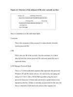
5.3.4 Versatile Register Set
The MIPS architecture has a total of thirty-two 32-bit general purpose registers, in
addition to the following main control registers: one dedicated Program Counter (PC),
one dedicated Status Register (Status), one interrupt/exception Cause Register (Cause),
one timer Count Register (Count), one timer Compare Register (Compare), and one
dedicated Exception Program Counter (EPC). Figure 5.1 contains a description of the
MIPS register set.
Register name Register usage
$zero Constant 0
$at Assembler temporary register
$v0–$v1 Return values
$a0–$a3 Function arguments
$t0–$t7 Temporary registers
Preserved registers
$t8–$t9 Temporary registers
$k0–$k1 Reserved for OS
$gp Global base pointer
$sp Stack pointer
$fp Frame pointer
Register number
$0
$1
$2–$3
$4–$7
$8–$15
$16–$23
$24–$25
$26–$27
$28
$29
$30
$31 $ra Return address
Figure 5.1: MIPS register usage
Please purchase PDF Split-Merge on www.verypdf.com to remove this watermark.
Introduction to the MIPS Microprocessor 4 9
www.newnespress.com
Each of the general-purpose registers are 32 bits in MIPS32 architectures and 64 bits in
MIPS64 architectures. The size of the Program Counter (PC) and Exception Program
Counter (EPC) control registers are also determined by the architecture — 32 bits in
MIPS32 and 64 bits in MIPS64. The main control register in the MIPS architecture is the
Status Register (CP0 register 12). Most execution control is determined via bits in the
Status Register, including the current mode of execution.
5.3.5 Register Defi nitions
There are four registers and one counter that are particularly important for ThreadX. They
are the Status Register, the Count Register, the Compare Register, the Cause Register, and
the Exception Program Counter. Following are descriptions of each.
The Status Register contains all the important information pertaining to the state of
execution. Figure 5.2 contains an overview of the MIPS Status Register (CP0 register 12).
Bits Content
31–28 CU0–CU3
27 RP
26 Reserved
25 RE
24–23 Reserved
22 BEV
21 TS
20 SR
19 NMI
18–16 Reserved
15–8 IM0–IM7
7–5 Reserved
4UM
3 Reserved
2 ERL
1 EXL
0IE
Figure 5.2: Status Register (CP0 register 12) overview
Please purchase PDF Split-Merge on www.verypdf.com to remove this watermark.
50 Chapter 5
www.newnespress.com
Figure 5.3 contains a description of the names, values, and meanings of the fi elds of the
Status Register.
The Count Register is used as a timer and is incremented by one on every other clock.
In conjunction with the Compare Register, it is useful in generating a periodic interrupt
source. In addition, the Count Register is often read and even written by diagnostic
software. It is also important to note that incrementing the Count Register can be disabled
while in debug mode by writing to the CountDM bit in the Debug register. Figure 5.4
contains a description of the Count Register.
Bit
position
Meaning
0 Interrupts Disabled
1 Interrupts Enabled
0 Interrupt Enable:
0 Normal Level
1 Exception Level
1 Exception Level:
0 Normal Level
1 Error Level
2 Error Level:
3 Value of 0
0 Kernel Mode
1 User Mode
4 User Mode:
5–7 Value of 0
0 Interrupt Disabled
1 Interrupt Enabled
8–15
Individual Interrupt
Enable:
16–18 Value of 0
0 Not NMI Reset
1 NMI Reset
19 NMI Reset:
0 Not Soft Reset
1 Soft Reset
20 Soft Reset:
21 TLB Shutdown
0 Normal Vector Location
1 Bootstrap Vector Location
22 Vector Location:
23–24 Value of 0
0 User Mode Uses Default
1 User Mode Reversed
Endianness
25
Enable Reverse Endian
References
26 Value of 0
27
Enables Reduced
Power Mode
0 Coprocessor Access
Not Allowed
1 Coprocessor Access Allowed
28–31
Name
IE
EXL
ERL
Reserved
UM
Reserved
IM0–IM7
Reserved
NMI
SR
TS
BEV
Reserved
RE
Reserved
RP
CU0–CU3 Coprocessor Enable:
Figure 5.3: Status Register (CP0 register 12) defi nition
Please purchase PDF Split-Merge on www.verypdf.com to remove this watermark.
Introduction to the MIPS Microprocessor 5 1
www.newnespress.com
The Compare Register is used in conjunction with the Count Register to generate timer
interrupts. When the Count Register reaches the value in the Compare Register an
interrupt is generated. Upon a timer interrupt, it is the responsibility of software to update
the Count and/or Compare Register in order to generate another timer interrupt. Figure 5.5
contains a description of the Compare Register.
The Cause Register indicates the source of the most recent interrupt or exception. Upon
entering the exception handler, software reads the Cause Register to determine what
processing is needed for the particular interrupt or exception. In addition, the Cause
Register also contains a limited amount of confi guration information, such as the interrupt
vector location. Figure 5.6 contains a description of the fi eld names, values, and meanings
for the Cause Register.
The Exception Program Counter (EPC) contains the address of the program execution at
the beginning of the most recent interrupt or exception. This address is used by the software
to return from an interrupt or exception. Figure 5.7 contains a description of the EPC.
5.3.6 Processor Modes
There are four basic processor modes in the MIPS architecture. Some modes are for
normal program execution, some are for interrupt processing, and others are for
handling program exceptions. The EXL, ERL, and UM of the Status Register defi ne
the current processor mode. Figure 5.8 shows these values and their associated
processor modes.
Fields
Name
Bits
Description
Read/
Write
Reset
State
Count 31:0 Interval counter.
R/W Undefined
Figure 5.4: Count Register (CP0 register 9) description
Fields
Name Bit(s)
Description
Read/
Write
Reset
State
Compare 31:0 Interval count compare value.
R/W Undefined
Figure 5.5: Compare Register (CP0 register 11) description
Please purchase PDF Split-Merge on www.verypdf.com to remove this watermark.
52 Chapter 5
www.newnespress.com
5.3.6.1 User Program Mode (Status.UM ϭ 1 )
This is one of several program execution modes. Because access to system registers is
not allowed in this mode, it is typically used by larger operating systems when executing
application level programs.
5.3.6.2 Exception Mode (Status.EXL ϭ 1 )
This is the mode in which interrupts on the MIPS architecture are processed. The
processor stays in this mode until an “ eret ” instruction is executed or until the bit is
manually modifi ed by the software. Note that typical applications have multiple interrupt
sources. In such cases, the software — after saving some of the registers on the stack —
must determine which interrupt source is responsible for the interrupt and process it.
Fields
Name Bit(s)
Description
Read/
Write
Reset
State
EPC 31:0 Exception Program Counter
R/W Undefined
Figure 5.7: Exception Program Counter (CP0 register 14) description
Fields
Name Bits
Description
BD 31
Indicates whether the last exception taken occurred in a
branch delay slot.
TI 30 Timer Interrupt.
CE 29 28 Coprocessor unit number referenced.
DC 27 Disable Count Register.
PCI 26 Performance Counter Interrupt.
IV 23
Indicates whether an interrupt exception uses the general
exception vector or a special interrupt vector.
WP 22 Indicates that a watch exception was deferred.
IP7 IP2 15 10 Indicates an interrupt is pending.
RIPL 15 10 Requested Interrupt Priority Level.
IP1 IP0 9 8 Controls the request for software interrupts.
ExcCode 6 2 Exception code.
0 25 24, 21 16, 7, 1 0 Must be written as zero; returns zero on read.
Figure 5.6: Cause Register (CP0 register 13) description
Please purchase PDF Split-Merge on www.verypdf.com to remove this watermark.
Introduction to the MIPS Microprocessor 5 3
www.newnespress.com
5.3.6.3 Kernel Mode (Status.UM ϭ 0 )
This is another typical program execution mode. Most embedded systems execute their
programs in this mode.
5.3.6.4 Error Mode (Status.ERL ϭ 1 )
This program exception mode is used for handling reset, soft reset, and NMI conditions.
Unlike the Exception Mode, the return address of the error is saved in the ErrorEPC
register instead of the EPC.
5.4 MIPS Power Saving Support
Most MIPS processors have the ability to enter low power mode. In this mode, the
processor is sleeping at the instruction used to enter low power mode and will stay in
this mode until an interrupt or a debug event occurs. When such an event occurs, the
processor completes the low power instruction and prepares for the interrupt just as it
would in normal processing.
ThreadX applications typically enter low power mode when the system is idle or when
a low priority application thread executes (indicating there is nothing else meaningful
to do). The only diffi cult aspect of entering low power mode is determining if there
are any periodic events currently scheduled. ThreadX supports the low power mode
processing by providing two utilities, namely tx_timer_get_next and tx_time_
increment . The tx_timer_get_next routine returns the next expiration time. It
should be called before entering low power mode and the value returned should be used
to reprogram the ThreadX timer (or other timer) to expire at the appropriate time. The
tx_time_increment utility is used when the processor awakes to adjust the internal
Status Register Bits
Processor Mode UM EXL ERL
User Program Mode 1 0 0
Exception Mode don't care 1 0
Kernel Mode 0 0 0
Error Mode don't care don't care 1
Figure 5.8: Processor modes
Please purchase PDF Split-Merge on www.verypdf.com to remove this watermark.
54 Chapter 5
www.newnespress.com
ThreadX timer to the number of timer-ticks that have expired while the processor was in
low power mode. By using these two services, the processor can enter low power mode
for signifi cant periods of time and without losing any accuracy of ThreadX time-related
features.
5.5 Key Terms and Phrases
Cause Register low power mode
CISC MIPS 32-bit mode
code density MIPS 64-bit mode
Compare Register MIPS architecture
Count Register orthogonal registers
Error Mode power saving
exception handler Program Counter
Exception Mode register set
Exception Program Counter RISC
exceptions single cycle execution
fi xed length instructions SoC
general purpose registers Status Register
instruction pipeline System-on-Chip
interrupt handling timer interrupt
Kernel Mode User Program Mode
load-store architecture
Please purchase PDF Split-Merge on www.verypdf.com to remove this watermark.
www.newnespress.com
MIPS Exception Handling
CHAPTER 6
6.1 Introduction
An exception is an asynchronous event or error condition that disrupts the normal fl ow
of thread processing. Usually, an exception must be handled immediately, and then
control is returned to thread processing. There are three exception categories in the MIPS
architecture, as follows:
●
Exceptions resulting from the direct effect of executing an instruction
●
Exceptions resulting as a side effect of executing an instruction
●
Exceptions resulting from external interrupts, unrelated to instruction execution
When an exception arises, MIPS attempts to complete the current instruction, temporarily
halts instruction processing, handles the exception, and then continues to process
instructions.
The processor handles an exception by performing the following sequence of actions.
1. Set the EXL bit (bit 1) of the Status CP0 Registers, which disables further interrupts
and causes the processor to execute at the Exception Level of execution.
2. Save the current PC (program counter — address of the next instruction) in the EPC
register.
3. Change the PC to the appropriate exception vector as illustrated in Figure 6.1 , which
is where the application software interrupt handling starts.
Please purchase PDF Split-Merge on www.verypdf.com to remove this watermark.
56 Chapter 6
MIPS has a simple exception and interrupt handling architecture. There are principally
two interrupt vectors, one for reset and another for general exception handling. Each
vector is an address that corresponds to where the processor starts execution upon the
exception condition. Figure 6.1 shows the standard MIPS vector area.
Some implementations of the MIPS architecture add additional interrupt vectors so that
each interrupt source can have a separate vector. In addition, some of these separate
vectors are given a shadow register set for improved interrupt performance. This scheme
has the advantage that the interrupt-handling software no longer has to determine which
interrupt source caused the interrupt.
6.2 ThreadX Implementation of MIPS Exception Handling
ThreadX is a popular RTOS for embedded designs using the MIPS processor. ThreadX
complements the MIPS processor because both are extremely simple to use and are very
powerful.
6.2.1 Reset Vector Initialization
ThreadX initialization on the MIPS processor is straightforward. The reset vector at
address 0xBFC00000 contains an instruction that loads the PC with the address of the
compiler’s initialization routine.
1
Figure 6.2 contains an example of a typical ThreadX
vector area, with the reset vector pointing to the entry function _start of the MIPS
compiler tools.
www.newnespress.com
Address BEV bit Vector
0xBFC00000 1
Reset vector—this is where MIPS starts
execution on reset or power up.
0xBFC00180 1
This is where MIPS starts executing when
an exception or normal interrupt occurs.
0x80000180 0
This is where MIPS starts executing when
an exception or normal interrupt occurs.
Figure 6.1: MIPS exception vector area
1
When you develop an application in C or C ϩϩ , the compiler generates application initialization
code, which must be executed on the target system before the application.
Please purchase PDF Split-Merge on www.verypdf.com to remove this watermark.