Models in Hardware Testing- P4 pot
Bạn đang xem bản rút gọn của tài liệu. Xem và tải ngay bản đầy đủ của tài liệu tại đây (1.01 MB, 30 trang )
3 Models for Delay Faults 79
SC1
D
SIN
SE
CK
Q
SD
SE
CK
SC3
CUT
SC2
DQ
SD
SE
CK
D Q SOUT
SD
SE
CK
Fig. 3.8 A scan chain
CLK
SE
IP
n
LP CP
Scan in pattern I
Scan out response i–1
Scan in pattern i+1
Scan out response i
Fig. 3.9 Timing diagram for two pattern tests using LOC test application method
clock cycle is applied to capture the circuit response to the test. SE is changed to 1
and the captured response is scanned out and at the same time the next test is shifted
in. For two pattern tests, two methods of test application called skewed-load (Savir
et al. 1993) also called launch off shift (LOS) and broadside (Savir et al. 1994)also
called launch off capture (LOC) are used. Both methods can be regarded to have
three phases. In the first phase, called initialization cycle or initialization phase (IP),
the first vector V1 of a two pattern test <V1,V2> is scanned in with SE D 1.
The two methods differ in the next phase called the launch phase or launch cycle
(LP). In LOS method the second vector V2 is obtained by shifting once with SE
staying at 1. Thus V2 is restricted to be a single shift of V1. In LOC test method
V2 is obtained through the combinational logic of the circuit by setting SE D 0.
Thus in LOC also V2 is obtained as a function of V1. In the third phase, called the
capture cycle (CP), in LOS method SE is changed to 0 and the response to the test
applied is captured. In LOC method SE is maintained at 0 and the response to the
test is captured as for the LOS method. The timing waveforms for the two methods
are shown in Figs. 3.9 and 3.10. From the waveforms for the LOS method it can be
80 S.M. Reddy
CLK
SE
IP LP CP
Scan in pattern I
Scan out response i–1
Scan in pattern i+1
Scan out response i
n
Fig. 3.10 Timing diagram for two pattern tests using LOS test application method
seen that SE has to change fast before the capture cycle. This implies that the SE net
must be designed similar to a clock network since it is also distributed to all the scan
cells (flip-flops). In LOC method SE has to switch after the initialization cycle and
this can happen as slowly as needed by, for example, introducing some idle cycles
after the initialization phase. In at-speed test the capture cycle, also referred to as
a fast capture cycle, is applied after one clock period of the desired frequency of
operation.
In practice, the following advantages and disadvantages of the LOS and LOC
test methods have been observed. Test generation times and test set sizes for LOS
method are much smaller and achievable fault coverage is higher compared to that
for LOC method. Additionally, when multiple scan chains are used as is typical in
large industrial designs to reduce test application time, fault coverage using LOS
tests increases compared to using a single scan chain (Pomeranz et al. 2002). Fault
coverage using LOC tests is independent of the number of scan chains used. How-
ever design effort to insure that SE can switch state fast is higher while a fast SE
is not needed for LOC test method. LOC tests are often preferred since they are
“closer” to the normal functional operation. It should be noted that in one scan de-
sign method called Level Sensitive Scan Design (LSSD) (Eichelberger et al. 1978)
all scan chain control signals are designed as clocks and hence both LOS and LOC
test methods can be used without any additional design effort. Both methods achieve
lower fault coverage than if arbitrary two-pattern tests are applicable, for example
using enhanced scan (Dasgupta et al. 1981) that has a three latch scan cell to enable
storing both patterns of a two pattern test. However using enhanced scan that adds
extra hardware overhead may not be acceptable for many designs.
3.1.5 Non-enumerative Procedures and Path Selection Methods
Since the number of paths in a realistic design could be extremely large and so could
be the number of tests to detect all detectable path delays, several methods have
been developed to address these issues. In order to reduce the impact of the size of
3 Models for Delay Faults 81
the set of path delay faults on fault simulation and test generation non-enumerative
procedures were first proposed in Pomeranz et al. (1994), Pomeranz et al. (1995b).
Non-enumerative methods do not explicitly consider all path delay faults. These
methods have been further developed, for example, in Gharaybeh et al. (1998),
Kagaris et al. (2002), Tragoudas et al. (1999). To assess the cost of test applica-
tion if all path delay faults are targeted, a method to determine a lower bound on
the number of tests to detect all path delay faults was proposed in Pomeranz et al.
(1996a).
Even though non-enumerative procedures help reduce fault simulation and test
generation times for path delay faults, still the number of tests to detect all path
delay faults is typically too large. For this reason procedures to select a subset of
path delay faults to be targeted for detection have been proposed. These include se-
lecting only paths of maximum delay, selecting paths whose delay is within up to a
certain percentage of the maximum and selecting a subset S of paths such that for
each circuit lead r there is at least one path in S whose delay is maximum among
all paths containing r (Malaiya et al. 1983; Smith 1985). A procedure of polynomial
complexity was developed in Li et al. (1989) to select a subset of minimum number
of paths S such that S contains at least one path of longest delay, for each circuit lead
r, among all paths through r. However, given that many path delay faults in a circuit
may not have tests, some or many faults in the selected subset may not be testable.
For this reason procedures that efficiently identify untestable paths have been de-
veloped (Lam et al. 1993; Cheng et al. 1993; Sparmann et al. 1995; Kajihara et al.
1997; Kajihara et al. 2000; Shao et al. 2001). The methods in Kajihara et al. (1997),
Kajihara et al. (2000), Shao et al. (2001) are non-enumerative and the key idea be-
hind these methods is illustrated in Fig.3.11. The methods find pairs of lines called
(b,f) pairs (Kajihara et al. 1997) such that there are paths between line b and line f of
the circuit and any path fault containing the two lines is untestable. The lines b and
f are logical lines which are physical lines with which a rising or falling transition is
associated. The pairs of lines considered are inputs to FFRs. Consider inputs a and c
of the two FFRs shown in Fig. 3.11. There are unique subpaths from a to b and c to d
in the two FFRs. If the necessary assignments to sensitize these two subpaths cannot
be justified simultaneously then all the path delay faults containing lines a and c are
untestable. In Murakami et al. (2000) a subset of path delay faults were selected that
a
b
c
d
e
…
…
Fig. 3.11 Determining untestable paths
82 S.M. Reddy
avoid (b,f) pairs of lines and such that the subset contains at least one path delay
fault for each circuit lead with maximum delay among all paths containing the lead.
Over 90% of the path delay faults in such subsets were found to be testable.
3.1.6 Additional Delay Fault Models
In addition to the basic delay fault models, gate and path delay faults, several other
fault models have been proposed. These include double and multiple transition fault
model (Pomeranz et al. 1996b) and the segment fault model (Heragu et al. 1996).
These fault models require tests that robustly propagate transitions through subpaths
containing pairs or multiple lines of circuits. Segment fault model considers a set
of two or more consecutive circuit lines. These fault models are more complex than
TDF model but are less demanding than path delay fault model.
Even though path delay faults model the effect of accumulated delays along the
circuit lines on the path a non-robust test for a path delay fault may not detect ex-
tra delay in a lead or a subpath of the path. This is illustrated in Fig. 3.12.Thetwo
pattern test shown in Fig. 3.12 is a non-robust test for the path b-d-f with a rising
transition at b. However, this test does not detect the STR fault on line b as shown by
the faulty circuit values under “/”. This means that if the circuit shown in Fig. 3.12
is part of a larger circuit a non-robust test for a path that contains the subpath b-d-f
may not detect accumulated excess delay up to line b. Given that many if not most
of the path delay faults can only be detected by non-robust tests, methods to gener-
ate non-robust tests to address this weakness were investigated. Towards this goal,
in Pomeranz et al. (2008a) a fault model called Transition Path Delay Faults was
proposed. This model requires that a test that detects a path delay fault also detects
appropriate transition delay faults on each on-path line.
In many designs handcrafted custom blocks are used for which accurate or even
any gate level descriptions may not be available. Tests for delay faults for such de-
signs need to consider them as black boxes. For such designs functional test methods
were proposed in Underwood et al. (1994)andPomeranz et al. (1995a).
X1
a
0 1/0
1 0
b
c
1 0/1
1 1/0
1 0
X
d
e
f
Fig. 3.12 Invalidation of a non-robust test
3 Models for Delay Faults 83
Resistive interconnect opens are one cause for delay defects. Noting that a re-
sistive open slows down both the rising and falling transition on the defective line,
Inline Resistance Fault model was proposed in Benware et al. (2004). An inline
resistance fault on line r is detected if either a slow to rise or a slow to fall fault
is detected on line r. Inline resistance fault model allows reduction in test patterns
compared to TDF fault model.
When determining TDF coverage by a given sequence for a non-scan sequential
circuit it is necessary to consider persistence of fault effects over more than one
clock cycle (Cheng 1993). This requires simulating the sequence several times with
different numbers of fault effect persistence cycles. In Pomeranz et al. (2008b) a
transition delay fault model called Unspecified Transition Fault model was proposed
which allows a one pass simulation of the given sequence.
3.2 Test Generation for TDFs and Small Delay Defects
In delay fault testing two conflicting goals need to be considered. One is achieving
as high defect coverage as possible and the other is to avoid over testing. Over
testing occurs due to non-functional operation during scan based test application
(Rearick 2001). In this section we review some of the recent works related to both
these issues.
As discussed above defects that increase circuit delays are modeled by gate de-
lay faults, transition delay faults (TDFs) and path delay faults. Application of tests
to detect all path delay faults is impractical and gate delay faults require accurate
timing models. For these reasons for the detection of delay defects in industrial de-
signs typically tests for TDFs are used together with tests for selected critical paths.
However tests for TDFs may not provide adequate coverage of delay defects that
are of small size. This can be seen by the example in Fig. 3.13. A TDF on line a
can be propagated either through path a-f-g-j or through a-f-k. Typically test pat-
tern generation tools propagate tests through easier to sensitize paths and hence the
k
d
f
e
g
h
j
a
b
c
X
Fig. 3.13 Gate delay faults
84 S.M. Reddy
fault may be propagated through the shorter path a-f-k. In this case the delay de-
fect size needs to be larger for it to be detected. However a defect of a smaller size
than detectable by the test will affect circuit operation when the transition on a is
propagated through the longer path under normal operation. For this reason meth-
ods to activate and propagate TDFs through longest delay paths have been proposed.
We review some of the recent works on generating TDF tests to detect small delay
defects.
3.2.1 Functional Broadside Tests
There are two reasons for non-functional operation in scan based tests. One is the
very fact that tests are shifted in to scan chains which is not a functional opera-
tion and the states of the circuit under tests go through many states that are not
functional. The other is during launch and capture cycles of the application of two
pattern tests non-functional operation may cause excessive switching activity that
may cause supply voltage droops and higher heat dissipation. Voltage droops cause
increase in circuit delays which may fail good chips (Saxena et al. 2003). Addition-
ally tests using non-functional operation may propagate faults along non-functional
paths potentially failing good chips even if the switching activity during test is not
excessive. In this section we discuss recently developed methods to address the issue
of non-functional operation during launch and capture cycles.
An LOC or broadside test can be represented by <s1,a,b>, where s1 is the state
scanned in and a and b are the primary input values. The state part of the second
pattern of the two pattern test is obtained through the functional logic. Hence if s1 is
a state that can be reached during normal functional operation then the circuit will
only operate within normal functional operation during test also. Observing this,
Functional Broadside Tests were proposed in Pomeranz et al. (2006). In a functional
broadside test the shifted in state s1 is a reachable state. A reachable state is a state
that can be reached from the state of the circuit after it is synchronized. Any state
reached after synchronization is a state that can occur during the normal operation
of the circuit. Functional broadside tests insure that switching activity and supply
current demands during launch and capture cycles are within those during normal
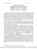
operation. Additionally no non-functional paths will be activated. In Table 3.2 the
numbers of TDFs detected by functional broadside tests (Lee et al. 2008)arecom-
pared with the numbers of faults detected using arbitrary broadside tests in full scan
ISCAS-89 circuits. In Table 3.2, after the circuit name the numbers of collapsed
TDFs are given followed by the numbers of faults detected by functional broad-
side and arbitrary broadside tests. From this data one can observe that numbers of
faults detected by the functional broadside tests are sometimes smaller as can be
expected. However, overall the numbers of detected faults are similar in most cir-
cuits. Expandingthe functional operationto include the state transitions encountered
during the application of a synchronizing sequence permits additional tests called
Synchronization Broadside Tests (Pomeranz et al. 2009a). These tests may shift in
3 Models for Delay Faults 85
Table 3.2 TDFs detected by
functional broadside tests
Circuit # Faults # Func. det # Arb. det
S298 508 403 403
S344 552 522 522
S349 566 505 530
S382 646 488 500
S386 690 505 530
S444 764 554 568
S526 948 571 590
S641 734 575 699
S713 918 648 777
S820 1;574 1;281 1;283
S832 1;614 1;290 1;290
S1196 2;110 2;108 2;108
S1238 2;316 2;234 2;234
S1423 2;512 2;207 2;239
S1488 2;770 2;529 2;529
S1494 2;810 2;548 2;548
S5378 7;040 5;353 6;412
S35932 63;502 54;599 54;599
unreachable states, however they are restricted to state transitions that occur during
synchronization of the circuit. Additional fault coverage beyond that obtained by
functional broadside tests can be obtained using the synchronization broadside tests
(Pomeranz et al. 2009a).
3.2.2 Pseudo-Functional Tests
Functional broadside tests require scanning in a reachable state. An alternate ap-
proach is to avoid shifting in an unreachable state. Unreachable states can be avoided
by implications learned from the sequential circuit. Several earlier works, for exam-
ple, Lin et al. (1998), Chen et al. (2003) used sequential static learning to identify
untestable stuck-at and TDF faults. These learned implications help in insuring that
the shifted in state of a broadside test is not an unreachable state. However, they
do not guarantee that a state that does not violate the learned implications is in-
deed a reachable state. For this reason tests generated using sequential learning are
called pseudo-functional tests (Lin et al. 2005). Several works have investigated
methods to generate pseudo-functional tests (Lin et al. 2005; Zhang et al. 2005;
Syal et al. 2006). In Table 3.3, the numbers of TDFs detected by pseudo-functional
broadside tests in larger ISACAS-89 benchmark circuits are given from Zhang
et al. (2005). As expected the sets of faults detected by pseudo-functional broad-
side tests are smaller and proper subsets of the faults detected by arbitrary broadside
tests. Also pseudo-functional tests cause less switching activity during launch and
capture cycles (Zhang et al. 2005). Another observation regarding the faults detected
86 S.M. Reddy
Table 3.3 TDFs detected by
pseudo-functional tests
Circuit # Det-pseudo # Det-arb
S3330 3,302 3,937
S5378 5,404 6,412
S9234 4,819 9,505
S13207 9,658 12,489
S15850 11,738 13,535
S38417 46,926 48,761
S35932 54,599 54,599
S38584 53,349 55,123
Fig. 3.14 A sequential
circuit with STR fault et al.
011
b×01
c
0 0 1/0
×01
PO
0 1/0 1/0
a
a1
a2
011
FF
by pseudo-functional tests is that even though in general LOS tests detect more
faults than LOC (broadside) tests many faults that are detected by functional and
pseudo-functional tests are not detected by LOS tests (Zhang et al. 2007a). Thus
LOS tests may cause test escapes that cause malfunction of circuits in normal
operation.
3.2.3 Tests with Multiple Activation Cycles
Tests to detect delay faults described so far used one launch cycle and one capture
cycle. The launch cycle activates and propagates the fault. However some delay
faults require multiple activation cycles for detection (Brand et al. 1994, Zhang
et al. 2006a, Abraham et al. 2006). This is illustrated using an example from Zhang
et al. (2006a).
Consider the sequential circuit shown in Fig. 3.14. Assume a slow to rise (STR)
TDF on line a1. By definition a transition fault represents a delay fault of large
(infinite) size. Consider a sequence of inputs 011 applied to a in three consecutive
clock cycles. The values on all the signal lines in the circuit are shown using the
standard notation of p/q to represent fault-free/faulty values on a signal line. It can
be seen that the TDF on a1 affects the circuit performance in the sense that in its
presence the circuit malfunctions when the input sequence 011 is applied. Now
consider generating a test to detect the STR fault on a1 using a standard single
activation cycle LOC test. Generation of such tests use an iterative logic array of two
time frames as illustrated in Fig. 3.15a. Clearly the STR fault at a1 is not detectable
since the fault effect is not propagated to the primary output or the flip-flop. A three
cycles test, which uses an ILA of three time frames, is illustrated in Fig. 3.15b.
3 Models for Delay Faults 87
The circuit with two time frames
a
b
c
0
a
0
FF FF
a1
a2
0
0
PO
b0
c
1
a
1
a1
a2
1/0
0
PO
The circuit with three time frames
b
b
c
0
a
0
FF FF
a1
a2
0
0
PO
b0
c
1
a
1
a1
a2
1/0
0
PO
FF
b1
c
1
a
1
a1
a2
1/0
1/0
PO
Fig. 3.15 LOC test for the circuit in Fig. 3.14
Using a three cycle test, with two activation cycles, the STR fault on a1 is detected
as shown by the 1/0 on output c in time frame 3. This example shows that TDFs
at some fault sites may not be detectable using LOC tests that use only one fault
activation cycle but may be detectable using tests with more than one activation
cycles. Similarly some TDFs not detected by two pattern LOS tests are detected by
LOS tests with multiple activation cycles (Zhang et al. 2006a).
In Table 3.4 results on TDF detection using multiple fault activation cycles are
given for ISCAS-89 circuits. After the circuit name the numbers of TDFs that can
be detected using enhanced scan are given. This is the maximum number of TDFs
that can be detected by any scan based tests. Next the numbers of faults detected
by single activation cycle using LOC, LOS and jointly by LOC and LOS tests are
given. Finally similar numbers are given when multiple activation cycles up to 11
are used. It can be seen that using multiple activation cycles and both LOC and LOS
test methods, for most of the benchmark circuits, the same fault coverage as that
achievable using enhanced scan can be achieved.
3.2.4 Tests for Small Delay Defects
In order to improve delay defect coverage whilst keeping the advantages of TDF
model, it has been proposed to use tests that activate and propagate TDF faults
through longest paths (Pramanick et al. 1989, Majhi et al. 1996, Shao et al. 2002).
Following is a brief review of one of these works (Shao et al. 2002).
Tests for TDFs can be classified in to six types, shown in Table 3.5, based on how
faults are activated and how they are propagated to observed outputs. In Table 3.5
SNRB and WNRB stand for strong non-robust and weak non-robust. Note that in
this classification robust activation and propagation are considered as contained in
88 S.M. Reddy
Table 3.4 TDFs detected by multi-cycle tests
Circuit Max. Det. Method Det. Sngl. Det. Mult.
S1423 2,488 LOC 2,239 2,450
LOS 2,412 2,488
LOC/S 2,476 2,488
S1488 2,770 LOC 2,529 2,728
LOS 2,211 2,770
LOC/S 2,694 2,770
S1494 2,794 LOC 2,548 2,753
LOS 2,225 2,794
LOC/S 2,718 2,794
S5378 6,961 LOC 6,412 6,428
LOS 6,522 6,960
LOC/S 6,899 6,961
S9234 10,698 LOC 9,517 9,687
LOS 9,882 10,698
LOC/S 10,608 10,698
S13207 15,379 LOC 12,489 13,193
LOS 13,377 15,333
LOC/S 14,895 15,367
S15850 18,403 LOC 13,535 14,920
LOS 17,176 18,343
LOC/S 17,752 18,385
S35932 56,446 LOC 54,599 56,257
LOS 56,446 56,446
LOC/S 56,446 56,446
S38417 49,544 LOC 48,761 49,039
LOS 48,560 49,544
LOC/S 49,487 49,544
S38584 58,979 LOC 55,129 56,811
LOS 56,118 58,963
LOC/S 58,060 58,979
Table 3.5 Six types of TDF tests
Activation Propagation
Type of path Sensitization Type of path Sensitization
Type-I Single SNRB Single SNRB
Type-II Multiple Functional Single SNRB
Type-III Single/multi Functional Multi SNRB
Type-IV Single SNRB Single WNRB
Type-V Multi Functional Single WNRB
Type-VI Single/multi Functional Multi WNRB
the strong non-robust activation and propagation. In Figs. 3.16 to 3.18 three of the
six types of tests are illustrated. Testable paths of largest delay are constructed by ex-
tending subpath(s) containing the fault site towards circuit inputs and circuit outputs.
3 Models for Delay Faults 89
P
1
P
2
f
SNRB
SNRB
Fig. 3.16 Type-I tests
P
1
P
1
P
2
P
2
f
SNRB
g
Fig. 3.17 Type-II tests
SNRB
SNRB
SNRB
f
g
P
1
P
2
Fig. 3.18 Type-III tests
During the process of path extension information on (b,f) pairs is used to guide the
path extension. Recall that all paths through a (b,f) pair are untestable. This is il-
lustrated in Fig. 3.19 for Type I and Type IV tests. Each time the current subpath
is extended a unique subpath through a FFR is chosen such that the extended path
does not contain any (b,f) pairs.
Methods to generate compact test sets that attempt to activate and detect TDFs
through largest delay paths have been proposed and a sketch of the method in Wang
et al. (2008b) is given next. The method in Wang et al. (2008b) first finds a testable
90 S.M. Reddy
Inputs
Outputs
f-line
f-line
b-line
l
b-line
Decision point
FFR
backward
expansion line
forward
expansion line
initial PP
I
Fig. 3.19 Step-wise path expansion
path of largest delay for each TDF. For each such path necessary assignments to
sensitize the path are found. Next clusters of TDFs such that the necessary assign-
ments of the largest delay paths for any pair of faults do not conflict are determined
together with the union of the necessary assignments for the largest delay paths of
the faults in the cluster. Let the union of the necessary assignments for a cluster be
CNA. Tests that satisfy all the necessary assignments in a CNA detect all the faults
in the cluster through largest delay paths.
A method proposed to improve delay defect coverage is to reduce the test clock
period to even less than the system clock period (Pramanick et al. 1990, Iyengar
et al. 1992). This will allow detection of delay defects smaller than the slacks of the
faults.
It is common to have device specifications that cover a range of supply voltage
and temperatures. It is also now common that devices are operated at different power
supply voltages to save power by dynamic supply voltage switching during run time
(Cai et al. 2007). For such devices methods to generate TDF tests through longest
paths need to consider the supply voltages and the range of operating conditions.
The longest paths through target fault sites change with supply voltage and operating
conditions such as temperature (Seshadri et al. 2005). However testing at several
supply voltages and temperatures may be costly in test time. One solution suggested
is to test at one or a minimal number of operating conditions and generate tests
to detect the target faults N times through longest paths, for a small value of N
(Seshadri et al. 2005). Testing more than one path may also be necessary to address
variations in the delay of paths through a circuit lead due to process variations.
Several metrics to evaluate the effectiveness of a given TDF test set S to de-
tect small defects (Pramanick et al. 1989; Park et al. 1989; Shao et al. 2002; Sato
et al. 2005; Lin et al. 2006) and to determine probability of test escapes and defect
levels have been proposed (Park et al. 1989; Sato et al. 2005).
Assume that the clock period of the capture cycle for tests used is Tc and the
system clock period is Ts. Consider a TDF on a logical line r of the circuit. Let
the maximum of the delays of all sensitizable paths (functional paths) through r be
3 Models for Delay Faults 91
Max(dr) and let the maximum of the delays of the paths through r used to detect the
fault by tests in S be Max(tr). The slack of line r slack.r/ D Ts – Max(dr) and let
the test slack of line rbe testslack.r/ D Tc – Max(tr). Typically Tc is larger than Ts.
A delay defect of size greater than or equal to slack(r) is detectable while the given
test only detects delay defects of size greater than or equal to testslack(r). If the
fault is not detected testslack(r) is defined to be infinity. Let the probability density
function of defect sizes on line r be P
r
(s), where s is the size of the defect. One can
compute the coverage of defects on line r,C
r
, by tests in S as given below:
C
r
D
Z
1
testslack.r/
P
r
.s/ds
Z
1
testslack.r/
P
r
.s/ds (3.1)
Note that if Ts D Tc and testslack(r) D slack(r) all defect sizes that are detectable at
r are detected by the tests in S and in this case C
r
is also 1. If the number of faults in
the set of faults F is N then the coverage of delay defects in the entire circuit, DDC,
can be computed as:
DDC D
X
r2F
C
r
=N (3.2)
Note that DDC will be equal to 1 if for every fault p in the circuit coverage C
p
is 1. Thus DDC is similar to the fault coverage metric typically used to report
the effectiveness of covering modeled faults by a test set. Equations 3.1 and 3.2
are obtained from the statistical delay fault coverage (SDFC) metric proposed in
Park et al. (1989) assuming that Tc and Ts can be different as assumed in Sato
et al. (2005) and that the circuit path delays are constants.
A difficulty in using the coverage metric in Eqs 3.1 and 3.2 is the need to know
the delays of sensitizable paths to compute slacks of fault sites. Instead one can use
maximum delay of the structural paths through circuit leads (Park et al. 1989)which
are typically higher than sensitizable path delays. A tighter estimate of Max(dr)
could be obtained by determining the longest delay functionally sensitizable paths
that do not contain any (b,f) pairs discussed in the last section. Another metric, used
in the statistical delay quality model (SDQM), proposed in Sato et al. (2005) mea-
sures probability of not detecting delay faults using a given test set. Delay quality
of a test set for a given fault r is defined as:
DQ.r/ D
Z
slack.r/
testslack.r/
P
r
.s/ ds (3.3)
The delay quality of a circuit with respect to a given test set is:
DQ D
X
r2F
DQ .r/=N (3.4)
DQ is an estimate of the probability that a chip that passed a given test set is defec-
tive. The metrics given in Eqs 3.1 through 3.4 require knowledge of the probability
density function of defects. Metrics that can be used without the knowledge of the
92 S.M. Reddy
probability density functions have also been proposed (Pramanick et al. 1992; Shao
et al. 2002; Lin et al. 2006). A metric proposed for the case where Pr (s) is not
known is called delay test coverage (DTC) (Lin et al. 2006)giveninEq.3.5 given
below. DTC can also be used with any test clock period Tc.
DTC D
X
r2F
Max .tr/=Max .dr/
!
.
N (3.5)
3.3 DFT Techniques
In this section design for test (DFT) techniques proposed recently to reduce design
effort for LOS test method and methods to increase delay fault coverage are dis-
cussed. In Section 3.3.1 two methods to reduce the design effort for LOS designs are
discussed. Both these methods do not require any additional global signals and use
only the signals already available in MUX-scan designs. In Sections 3.3.2 a method
to increase delay fault coverage using multiple scan enable signals is outlined. In
Section 3.3.3 achieving higher delay fault coverage using segmented scan designs is
discussed.
3.3.1 LOS Testing Using Slow Scan Enable
As pointed out in Section3.1.4, for MUX scan LOS tests require scan enable line to
switch fast from 1 to 0. This is typically achieved by pipeline design for distributing
scan enable line which has high design time overhead and area overhead. In Ahmed
et al. (2007) a method to locally generate fast scan enable signal from a slow scan
enable signal has been proposed. The method adds one or more additional cells
called LTG cell, shown in Fig. 3.20, to each scan chain as illustrated in Fig. 3.21.In
Fig. 3.20 SD is the scan data, GSEN is the global slow scan enable, and LSEN is
the fast scan enable signal. Each LSEN drives the scan enable signals of a subset
of scan cells which are close to it. When the initialization pattern is scanned in,
the flip-flops in the LTG cell, which are part of the scan chain, are loaded with 01.
GSEN is changed to 0 after initialization phase as for LOC test. However the LSEN
signals which drive the scan cells changes only on the leading edge of the launch
cycle. Thus during the launch cycle LSEN is 1 thus the second pattern of the test is
obtained by a shift of the first pattern as required for LOS tests.
An alternate method to generate a fast scan enable signal proposed in Xu
et al. (2007) replaces each scan cell by, what is called, a DTS flip-flop shown in
Fig. 3.22.InFig.3.22 the select input of the multiplexer in the scan cell is driven
by the Timed Multiplexer Control (TMC) signal. TMC is the fast scan enable signal
in this design. The timing waveform for the operation of DTS flip-flop is shown
3 Models for Delay Faults 93
DQ
DQ
0
1
SD
GSEN
LSEN
Clock
Fig. 3.20 LTG cell
……
LTG
LSEN
Fig. 3.21 A scan chain with an LTG cell inserted
DQ
0
1
S
in
D
in
TMC
SE
CL
Fig. 3.22 DTS flip-flop
in Fig. 3.23. The global scan enable signal SE changes to 0 after the initialization
cycle. However the local scan enable signal TMC of each scan cell changes to 0 on
the leading edge of the launch cycle. Thus during the launch cycle the scan chain is
shifted to generate the second pattern of the test.
94 S.M. Reddy
Clock
SE
TMC
IC
LC
CC
Fig. 3.23 DTS flip-flop operation
p
2B
1B
3B
a
b
3A
2A
1A
c
d
e
f
g
h
i
j
k
m
n
Y
Z
Fig. 3.24 An example to illustrate higher fault coverage using multiple scan enables
3.3.2 Multiple Scan Enable Signals
As noted earlier delay fault coverage using LOC test method are typically lower than
the coverage obtained using LOS test method. In order to increase fault coverage us-
ing LOC tests use of multiple scan enable signals was investigated in Devtaprasanna
et al. (2005). The following example from Devtaprasanna et al. (2005) illustrates
how some faults not detected using a single scan enable are detected using multiple
scan enable signals.
Consider the circuit shown in Fig. 3.24. Consider the line g STF TDF. This fault
is untestable using the LOC test method since the initialization condition a D d D 1
implies h D 1 during the launch cycle. Thus the fault effect is blocked from being
propagated to flip-flop 1A during the capture cycle. Similarly, the line n STR TDF
is LOC untestable. Next, assume that there are two scan enable signals SEN
1
and
SEN
2
with SEN
1
connected to flip-flops 1A, 2A, 1B and 2B and SEN
2
connected to
flip-flops 3A and 3B as shown in Fig. 3.25a. SIN
AandSINB are the two scan-in
inputs. Figure 3.25b shows the timing diagram for a test in which SEN1 is 0 and
SEN2 is 1 during launch and capture. Figure 3.25c shows the contents of the flip-
flops in the two scan chains during initialization (IC), launch (LC) and capture (CC)
3 Models for Delay Faults 95
2A 3A1A
1B 2B 3B
SEN
1
SEN
2
a
SIN_A
SO_A
SO_B
SIN_B
b
clock
IC LC CC
SEN
1
SEN
2
c
1A
2A
3A
1B
2B
3B
IC
X
0
X
1
1
X
LC
1
X
0
0
0
1
CC
0/1
X
X
0
0
0
Fig. 3.25 Circuit of Fig. 3.24 with two scan enable signals
cycles required to test line g STF fault. Initialization vector (1A, 2A, 3A, 1B, 2B,
3B) D (X,0,X,1,1,X)(XD don’t care) is scanned in with both the scan enables
SEN1 and SEN2 set to 1. Both flip-flops 1B and 2B are initialized to 1 to set line
g to 1. Then the scan enable signal SEN1 is switched to 0 before the launch and
capture clocks are applied while SEN2 is held at 1 throughout this test. Assume that
the circuit inputs Y and Z (cf. Fig. 3.24) are both set to 0 during launch and capture
cycles. During the launch cycle flip-flops 1B and 2B are set to 0 and a 1 ! 0
transition is launched at the fault site. If an STF fault exists on g, then the value of
line g will be 1 during the capture cycle instead of 0. Since SEN2 D 1, flip-flop 3A
receives its launch cycle value (0) from flip-flop 2A instead of through its functional
data input. Therefore the fault effect is propagated to flip-flop 1A during capture
cycle and captured since SEN1 is 0. Similarly line n STR fault can be detected if
SEN1 D 0 and SEN2 D 1 during the launch and capture cycles. Thus both the LOC
untestable TDFs can be tested using two independent scan enable signals instead of
one scan enable signal.
In the test discussed above the scan enable signals are held constant at 1 or 0
during the launch and capture cycles and hence they do not need to switch fast. Also
96 S.M. Reddy
the scan cells connected to the scan enable signals that are at 1 shift during launch
and capture cycles and hence do not capture test responses and the achievable fault
coverage with this method can be expected to strongly depend on the grouping of
scan cells into subsets driven by different scan enable signals. In Devtaprasanna
et al. (2005) two different methods to group scan cells were investigated. It is im-
portant to note that when multiple independent scan enable signals are used standard
LOC tests can still be applied with all scan enables set to 0 during launch and capture
cycles. Thus the fault coverage using multiple scan enables is not lower than that by
LOC test method using a single scan enable signal. Additionally, it was shown that
multiple scan enable lines facilitate generation and application of tests with reduced
switching activity during scan shift and capture cycles (Wang et al. 2007). Thus use
of multiple independent scan enable signals facilitates simultaneous achievement of
higher delay fault coverage and reduced switching activity during test.
3.3.3 Higher Delay Fault Coverage Using Segmented
Scan Designs
Segmented scan design was proposed to reduce switching activity during loading of
scan based tests (Whetsel 2000). Segmented scan design is illustrated in Fig. 3.26
taken from Zhang et al. (2007b) which shows a scan chain divided in to three
Fig. 3.26 A segmented scan
design
a
A Single Scan Chain
SIN
123
SOUT
CLK
SEN
A Three Segment Scan Chain
b
SIN
S
C
A
N
C
O
N
T
R
O
L
CLK1
SO1
CLK2
SO2
CLK3
SO2
SOUT
SEN
Segment 1
Segment 2
Segment 3
3 Models for Delay Faults 97
segments. All segments share one scan-in and one scan-out lines. Each segment
can thus be loaded and unloaded independently while the other segments are inac-
tive. This reduces the switching activity during scan loads and unloads. Also if each
segment can be independently clocked each segment can independently capture thus
permitting reduced switching activity in capture cycles (Rosinger et al. 2004). The
clocks and the tri-state buffers at scan-outs are controlled through additional logic as
shown in Fig. 3.26.InLee et al. (2004)andRosinger et al. (2004)itwasshownthat
stuck-at fault coverage for segmented scan designs is the same as for the correspond-
ing unsegmented scan designs. However the number of test patterns could be lower
for segmented designs using appropriate test generation procedures (Zhang 2006b).
For some circuits segmented designs may require fewer stuck-at patterns than the
minimum possible number of test patterns for the corresponding unsegmented de-
sign (Zhang 2006b). As for delay faults, segmented scan designs may have higher
fault coverage, as discussed below, due to the fact that many different combinations
of launch and capture in different segments can be used.
Consider LOC tests in which the first vector V1 of a two pattern test <V1,V2>
is scanned in. In a design with two segments the first pattern is shifted in to the
segments one at a time as shown in Fig. 3.26 where the scan load cycles are shown
under SC. In non-segmented designs after scanning in V1 two capture cycles launch
and capture cycles are applied to the scan chain. For a two segment scan design one
can apply a capture cycle to segment 1 followed by a capture cycle to segment 2 as
showninFig.3.27a. In this case the capture cycle applied to segment 1 launches the
second vector V2 of the two pattern test which is comprised of the captured values in
segment 1 and the shifted in values in segment 2 of V1. The capture cycle applied to
segment 2 captures the test response and no test response is captured in segment 1.
Other possibilities of launch and capture for two pattern tests are shown in Fig. 3.27.
In Fig. 3.27e both segments are simultaneously applied launch and capture cycles
which amounts to be the same as in the case of unsegmented scan. Since there
are many different launch and capture scenarios which increase in number with
increasing numbers of segments many tests not possible using unsegmented can
be applied. Thus, higher delay fault coverage can be obtained in segmented scan
designs. The following example from Zhang et al. (2007b) illustrates this.
Consider the sequential circuit with two flip-flops shown in Fig. 3.28a. The set
of TDFs in this circuit are shown on the right in Fig. 3.28a. The two copies of the
circuit shown in Fig. 3.28b through d represent the two time frame iterative logic
array used to generate two pattern LOC tests. If a single unsegmented scan chain is
used, the four TDFs on the right of Fig. 3.28b cannot be detected. However, if a two
segment design is used with SC
i
in segment i, i D 1, 2, then the following faults
are not detected. Using launch off segment 1 and capturing in both the segments
the three faults shown on the right of Fig.3.28c are not detectable. Using launch off
segment 2 and capturing test response in both the segments one fault shown on the
right of Fig. 3.27d is not detected. It should be noted that the fault coverage with
a given launch method can be achieved either capturing in both segments or in a
single segment as long as responses are captured in both segments by the tests used.
98 S.M. Reddy
SC
Segment 1
LC
SC
Segment 2
CC
SC
Segment 1
LC CC
SC
Segment 2
SC
Segment 1
LC
CC
SC
Segment 2
CC
SC
Segment 1
LC
CC
SC
Segment 2
LC
SC
Segment 1
LC
CC
SC
Segment 2
LC
CC
a
b
c
d
e
Fig. 3.27 Various ways to launch and capture in a segmented scan chain design
This is in general true independent of the number of segments. That is, the fault
coverage using any selected launch method is the same independent of the capture
scheme used as long as capturing in every segment is considered.
From Fig. 3.28b through d it can be noted that using LOC tests that launch off a
single segment achieves better coverage than launching off both segments as done
using unsegmented design. It was found that this is true in most of the ISCAS-89
benchmark circuits (Zhang et al. 2007b). Additionally, it can be seen that if the nor-
mal LOC that launches all segments is used together with launching off the second
segment 100% TDF coverage can be obtained for the circuit in Fig. 3.28. Thus, us-
ing a combination of launching schemes it is possible to achieve much higher TDF
coverage in segmented scan designs in addition to reduced switching activity dur-
ing test. Finally, even though the discussion above used LOC tests for TDFs similar
observations are valid for LOS tests and for other delay fault models.
3 Models for Delay Faults 99
A full scan circuit
STR STF
a
STR STF
b
STR STF
c
STR STFd
STR STF
e
STR STFf
STR STF
g
STR STFh
STR STF
i
a
b
c
d
e
f
g
h
i
SC
1
SC
2
a
c
Test generation with only segment 1 launching
a
b
c
d
e
f
g
h
i
SC
1
SC
1
SC
2
SC
2
a
b
c
d
e
f
g
h
i
SC
1
SC
2
STRb
Unt. Flts.
STF
b
STRf
d
Test generation with only segment 2 launching
a
b
c
d
e
f
g
h
i
SC
1
SC
1
SC
2
SC
2
a
b
c
d
e
f
g
h
i
SC
1
SC
2
STRb
Unt. Flt.
b
LOC test with unsegmented scan chain design
a
b
c
d
e
f
g
h
i
SC
1
SC
1
SC
2
SC
2
a
b
c
d
e
f
g
h
i
SC
1
SC
2
STRd
Unt. Flts.
STR
e
STRf
STR
g
Fig. 3.28 An example illustrating higher TDF coverage in segmented scan designs
3.4 Summary
In this chapter basic fault models for defects that increase signal propagation de-
lays in digital logic circuits were presented together with methods to generate and
apply tests to detect modeled faults. Methods to detect small delay faults and de-
sign for test methods to improve delay fault coverage and reduce design effort were
discussed. There is a vast amount of literature on delay faults that could not be
reviewed in the chapter. Among the topics not discussed in the chapter are built-
in-self-test methods and fault diagnosis. Additional material and in-depth treatment
100 S.M. Reddy
can be obtained from several books, book chapters and review articles that cover de-
lay fault testing in greater detail (Krstic et al. 1998; Pomeranz et al. 1998; Bushnell
et al. 2000; Jha et al. 2003; Wang et al. 2008a).
References
Abraham J, Goel U, Kumar A (Apr 2006) Multi-cycle sensitizatizable transition delay faults. Pro-
ceedings of VLSI test symposium, pp 308–313
Abramovici M, Breuer M, Friedman AD (1990) Digital systems testing and testable design. IEEE
Press
Ahmed N, Tehranipoor M, Ravikumar CP, Butler KM (May 2007) Local at-speed scan enable
generation for transition fault testing using low-cost testers. IEEE Trans Comput-Aided Des
Integrat Circuits Sys 26:896–906
Barzilai Z, Rosen B (Sep 1983) Comparison of AC self-testing procedures. Proceedings of inter-
national test conference, pp 89–94
Benware B, Liu C, Van Slyke J, Krishnamurthy P, Madge R, Keim M, Kassab M, Rajski J (Oct
2004) Affordable and effective screening of delay defects in ASICS using the inline resistance
fault model. Proceedings of international test conference, pp 1285–1294
Brand D, Iyengar VS (Oct 1994) Identification of redundant delay faults. IEEE Trans Comput-
Aided Des Integrat Circuits Sys 13:553–565
Breuer MA (Oct 197) The effects of races, delays, and delay faults on test generation. IEEE Trans
Comput C-23:1078–1092
Bushnell M, Agrawal VD (2000) Essentials of electronic testing for digital, memory, and mixed
signal circuits. Frontiers in electronic testing volume 17. Springer
Cai Y, Schmitz MT, Al-Hashimi BM, Reddy SM (Jan 2007) Workload-ahead-driven online energy
minimization techniques for battery-powered systems with time-constraint. ACM transaction
on design automation of electronic systems, vol 12
Carter JL, Iyengar VS, Rosen BK (Sep 1987) Efficient test coverage determination for delay faults.
Proceedings of international test conference, pp 418–427
Chen G, Reddy SM, Pomeranz I (Oct 2003) Procedures for identifying untestable and redundant
transition faults in synchronous sequential circuits. Proceedings of international conference on
computer design: VLSI in computers and processors, pp 36–41
Cheng K-T, Chen H-C (Sep 1993) Delay testing for non-robust untestable circuits. Proceedings of
international test conference, pp 954–961
Cheng K-T (Dec 1993) Transition fault testing for sequential circuits. IEEE Trans Comput-Aided
Des Integrat Circuits Sys 12:1971–1983
Cheng K-T, Chen H-C (Aug 1996) Classification and identification of nonrobust untestable path
delay faults. IEEE Trans Comput-Aided Des Integrat Circuits Sys 15:845–853
Dasgupta S, Walthers RG, Williams TW, Eichelberger EB (Jun 1981) An enhancement to LSSD
and some applications of LSSD in reliability, availability and serviceability. Proceedings of
international symposium on fault-tolrant computing, pp 880–885
Devtaprasanna N, Gunda A, Krsihnamurthy P, Reddy SM, Pomeranz I (Oct 2005) A novel method
of improving transition delay fault coverage using multiple scan enable signals. Proceedings of
international conference on computer design: VLSI in computers and processors, pp 471–474
Dumas D, Girard P, Landrault C, Pravossoudovitch S (Oct 1993) An implicit delay fault simula-
tion method with approximate detection threshold calculation. Proceedings of international test
conference, pp 705–713
Eichelberger EB, Williams TW (1978) A logic design structure for LSI testability. J Des Automa-
tion Fault-Tolerant Comput 2:165–178
3 Models for Delay Faults 101
Gharaybeh MA, Bushnell ML, Agrawal VD (Apr 1998) The path-status graph with applications to
delay fault simulation. IEEE Trans Comput-Aided Des Integrat Circuits Sys 17:324–332
Guo R, Venkataraman S (Sep 2006) An algorithmic technique for diagnosis of faulty scan chains.
IEEE Trans Comput-Aided Des Integrat Circuits Sys 25:1861–1868
Heragu K, Patel JH, Agrawal VD (Jan 1996) Segment delay faults: a new fault model. Proceedings
of international conference on VLSI design conference, pp 32–39
Iyengar VS, Rosen BK, Waicukauski JA (Mar 1990) On computing the sizes of detected delay
faults. IEEE Trans Comput-Aided Des Integrat Circuits Sys 9:299–312
Iyengar VS, Vijayan G (Nov 1992) Optimized test application timing for AC testing. IEEE Trans
Comput-Aided Des Integrat Circuits Sys 11:1439–1449
Jha NK, Gupta S (2003) Testing of digital systems. Cambridge University Press
Kagaris D, Tragoudas S (Sep 2002) On the nonenmerative path delay fault simulation problem.
IEEE Trans Comput-Aided Des Integrat Circuits Sys 21:1095–1101
Kajihara S, Kinoshita K, Pomeranz I, Reddy SM (Jan 1997) A method for identifying robust depen-
dent and functionally unsensitizable paths. Proceedings of international conference on VLSI
design conference, pp 82–87
Kajihara S, Shimono T, Pomeranz I, Reddy SM (Dec 2000) Enhanced untestable path analysis
using edge graphs. Proceedings of Asian test symposium, pp 139–144
Ke W, Menon PR (Feb 1995) Synthesis of delay-verifiable combinational circuits. IEEE Trans
Comput 44:213–222
Konuk H (Oct 2000) On invalidation mechanisms for non-robust delay tests. Proceedings of inter-
national test conference, pp 393–399
Krstic A, Cheng K-T (1998) Delay fault testing for VLSI circuits. Frontiers in electronic testing,
Springer
Lam WK, Saldanha A, Brayton RK, Sangiovanni-Vincentelli AL (Jun 1993) Delay fault coverage
and performance tradeoffs. Proceedings of design automation conference, pp 446–451
Lee K-J, Hsu S-J, Ho C-M (Nov 2004) Test power reduction with multiple capture orders. Pro-
ceedings of Asian test symposium, pp 26–31
Lee H, Pomeranz I, Reddy SM (Mar 2008) On complete functional broadside tests for transition
faults. IEEE Trans Comput-Aided Des Integrat Circuits Sys 27:583–587
Li WN, Reddy SM, Sahni S (Jan 1989) On path selection in combinational logic circuits. IEEE
Trans Comput-Aided Des Integrat Circuits Sys 8:56–63
Lin CJ, Reddy SM (Sep 1987) On delay fault testing in logic circuits. IEEE Trans Comput-Aided
Des Integrat Circuits Sys 6:694–703
Lin X, Pomeranz I, Reddy SM (Oct 1998) On finding undetectable and redundant faults in syn-
chronous sequential circuits. Proceedings of international conference on computer design:
VLSI in computers and processors, pp 498–503
Lin Y-C, Lu F, Yang K, Cheng K-T (Jan 2005) Constraint extraction for pseudo-functional scan-
based delay testing. Proceedings of Asia and South Pacific design automation conference,
pp 166–171
Lin X, Tsai K-H, Kassab M, Rajski J, Kobayashi T, Klingenberg R, Sato Y, Hamada S, Aikyo
T (Nov 2006) Timing-aware ATPG for high quality at-speed testing of small delay defects.
Proceedings of Asian test symposium, pp 139–146
Majhi AK, Jacob J, Patnaik LM, Agrawal VD (Jan 1996) On test coverage of path delay faults.
Proceedings of international conference on VLSI design conference, pp 418–421
Malaiya YK, Narayanaswamy R (Oct 1983) Testing for timing faults in synchronous sequential
circuits. Proceedings of international test conference, pp 560–571
Murakami A, Kajihara S, Sasao T, Pomeranz I, Reddy SM (Oct 2000) Selection of potentially
testable path delay faults for test generation. Proceedings of international test conference,
pp 376–384
Park ES, Mercer MR, Williams TW (Feb 1989) A statistical model for delay-fault testing. IEEE
Des Test Comput 6:45–55
Pomeranz I, Reddy SM (Jun 1992) At-speed delay testing of synchronous sequential circuits. Pro-
ceedings of ACM/IEEE design automation conference, pp 177–181
102 S.M. Reddy
Pomeranz I, Reddy SM (Feb 1994) An efficient non-enumerative method to estimate the path delay
fault coverage in combinational circuits. IEEE Trans Comput-Aided Des Integrat Circuits Sys
13:240–250
Pomeranz I, Reddy SM (Nov 1995) Functional test generation for delay faults in combinational
circuits. Proceedings of international conference on computer-aided design, pp 687–694
Pomeranz I, Reddy SM, Uppaluri P (Dec 1995) NEST: a non-enumerative test generation method
for path delay faults in combinational circuits. IEEE Trans Comput-Aided Des Integrat Circuits
Sys 14:1505–1515
Pomeranz I, Reddy SM (Jan 1996a) On the number of tests to detect all path delay faults in com-
binational logic circuits. IEEE Trans Comput-Aided Des Integrat Circuits Sys 15:50–62
Pomeranz I, Reddy SM, Patel JH (Mar 1996b) On double transition faults as a delay fault model.
Proceedings of Great Lakes symposium on VLSI, pp 282–287
Pomeranz I, Reddy SM (1998) Delay fault models for VLSI circuits. Integrat VLSI J 26:21–40
Pomeranz I, Reddy SM (Sep 2002) On the coverage of delay faults in scan designs with multiple
scan chains. Proceedings of international conference on computer design: VLSI in computers
and processors, pp 206–209
Pomeranz I, Reddy SM (Oct 2006) Generation of functional broadside tests for transition faults.
IEEE Trans Comput-Aided Des Integrat Circuits Sys 25:2207–2218
Pomeranz I, Reddy SM (Jan 2008) Transition path delay faults: a new path delay fault model for
small and large delay defects. IEEE Trans VLSI Sys 16:98–107
Pomeranz I, Reddy SM (Jan 2008) Unspecified transition fault model: a transition fault model for
at-speed fault simulation and test generation. IEEE Trans Comput-Aided Des Integrat Circuits
Sys 27:137–146
Pomeranz I, Reddy SM (Jan 2009) Functional broadside tests under an expanded definition
of functional operation conditions. IEEE Trans Comput-Aided Des Integrat Circuits Sys
28:121–129
Pomeranz I, Reddy SM (2009) Hazard-based detection conditions for improved transition fault
coverage of scan-based tests. IEEE Trans VLSI Sys 17
Pramanick AK, Reddy SM (Sep 1989) On the detection of delay faults. Proceedings of interna-
tional test conference, pp 680–687
Pramanick AK, Reddy SM (Mar 1990) On the fault coverage of gate delay fault detecting tests.
Proceedings of European Design Automation Conference (EDAC), pp 334–338
Pramanick AK, Reddy SM (Jan 1997) On the fault coverage of gate delay fault detecting tests.
IEEE Trans Comput-Aided Des Integrat Circuits Sys 16:78–94
Rearick J (Oct 2001) Too much delay fault coverage is a bad thing. Proceedings of international
test conference, pp 624–633
Reddy SM, Pomeranz I, Kajihara S, Murakami A, Takeoka S, Ohta M (Oct 2000) On validating
data hold times for flip-flops in sequential circuits. Proceedings of international test conference,
pp 317–325
Rosinger P, Al-Hashimi BM, Nicolici N (Jul 2004) Scan architecture with mutually exclusive scan
segment activation for shift-and-capture-power reduction. IEEE Trans Comput-Aided Des In-
tegrat Circuits Sys 23:1142–1153
Sato Y, Hamada S, Maeda T, Takatori A, Kajihara S (Jan 2005) Evaluation of the statistical
delay quality model. Proceedings of Asia and South Pacific design automation conference,
pp 305–310
Savir V, Patil S (Aug 1993) Scan-based transition test. Trans Comput-Aided Des Integrat Circuits
Sys 12:1232–1241
Savir J, Patil S (Aug 1994) Broad-side delay test. Trans Comput-Aided Des Integrat Circuits Sys
13:1057–1064
Saxena J, Butler KM, Jayaram VB, Kundu S, Arvind NV, Sreeprakash P, Hachinger M (Sep 2003)
A case study of ir-drop in structured at-speed testing. Proceedings of international test confer-
ence, pp 1098–1104
Seshadri B, Pomeranz I, Reddy SM (May 2005) Path-oriented transition fault test generation con-
sidering operating conditions. Proceedings of European test symposium, pp 54–59
3 Models for Delay Faults 103
Schulz MH, Trischler E, Sarfert TM (Jan 1988) SOCRATES: a highly efficient automatic test
pattern generation system. IEEE Trans Comput-Aided Des Integrat Circuits Sys 7:126–137
Shao Y, Reddy SM, Kajihara S, Pomeranz I (Nov 2001) An efficient method to identify untestable
path delay faults. Proceedings of Asian test symposium, pp 233–238
Shao Y, Pomeranz I, Reddy SM (Nov 2002) On generating high quality tests for transition faults.
Proceedings of Asian test symposium, pp 1–8
Sinanoglu O, Schremmer P (Apr. 2007) Diagnosis, modeling and tolerance of scan chain hold-time
violations. Proceedings of design automation and test in Europe conference
Smith GL (Sep 1985) Model for delay faults based upon paths. Proceedings of international test
conference, pp 342–349
Sparmann U, Luxenburger D, Cheng K-T, Reddy SM (Jun 1995) Fast identification of robust de-
pendent path delay faults. Proceedings of design automation conference, pp 119–125
Syal M, Chandrasekar K, Vimjam V, Hsiao MS, Chang Y-S, Chakravarty S (Oct 2006) A study of
implication based pseudo functional testing. Proceedings of international test conference
Tragoudas S, Karayiannis D (Jul 1999) A fast nonenumerative automatic test pattern generator for
path delay faults. IEEE Trans Comput-Aided Des Integr Circuits Sys 18:1050–1057
Underwood B, Law W-O, Kang S, Konuk H (Oct 1994) Fastpath: a path-delay test generator for
standard scan designs. Proceedings of international test conference, pp 154–163
Waicukauski J, Lindbloom E, Rosen B, Iyengar V (Apr 1987) Transition fault simulation. IEEE
design and test, pp 32–38
Wang S, Wei W (Jan 2007) A technique to reduce peak current and average power dissipation
in scan designs by limited capture. Proceedings of Asia and South Pacific design automation
conference, pp 810–816
Wang LT, Stroud C, Touba N (2008) System on chip test architectures. Morgan Kaufmann
Publishers
Wang Z, Walker DMH (May 2008) Dynamic compaction for high quality delay test. Proceedings
of VLSI test symposium, pp 243–248
Whetsel L (Oct 2000) Adapting scan architecture for low power operation. Proceedings of interna-
tional test conference, pp 863–872
Xu G, Singh AD (May 2007) Scan cell design for launch-on-shift delay tests with slow scan enable.
IET Comput Dig Tech 1:213–219
Zhang Z, Reddy SM, Pomeranz I (Oct 2005) On generating pseudo-functional delay fault tests for
scan designs. Proceedings of IEEE international symposium on defect and fault tolerance in
VLSI systems, pp 398–405
Zhang Z, Reddy SM, Pomeranz I, Lin X, Rajski J (Apr 2006) Scan tests with multiple fault activa-
tion cycles for delay faults. Proceedings of VLSI test symposium, pp 343–348
Zhang Z (Dec 2006) New test generation methods for transition delay faults in scan designs. Ph.D.
Thesis, University of Iowa, Iowa City, Iowa, USA
Zhang Z, Reddy SM, Pomeranz I (Jan 2007) Warning: launch off Shist tests for delay faults may
contribute to test escapes. Proceedings of Asia and South Pacific design automation conference,
pp 817–822
Zhang Z, Reddy SM, Pomeranz I, Rajski J, Al-Hashimi BM (May 2007) Enhancing delay
fault coverage through low-power segmented scan. IET computers and digital techniques,
pp 220–229