Brushless Permanent Magnet Motor Design- P4 docx
Bạn đang xem bản rút gọn của tài liệu. Xem và tải ngay bản đầy đủ của tài liệu tại đây (5.62 MB, 30 trang )
Brushless Motor Operation
because the layout of the end turns is subject to few restrictions and
a set magnetic field distribution is impossible to define. As a result,
the end turn inductance is often roughly approximated, e.g., LiwschitzGarik and Whipple (1961).
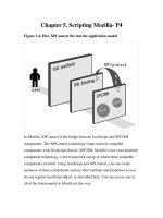
The approach followed here for computing end turn leakage inductance is to use the coenergy approach, expressed by (4.17), and to
assume that the magnetic field is distributed about the end turns in
the same way that it is about an infinitely long cylinder having a
surface current/, as illustrated in Fig. 4.19.
If the current I is equal to ni, then from (4.17) the inductance of a
section of the cylinder of length Z out to a radius R is
\r
2 77
(4.20)
Application of this expression to find the end turn leakage inductance
requires finding appropriate values for Z, R, and r. If the end turns
are semicircular as shown in Fig. 4.20, then these parameters can be
approximated by
Z =
R
77" 7"n
- Ì
cLqw
r, =
V
IT
r
=
dsws
27
Figure 4.19 Magnetic field about a cylindrical conduc-
tor.
(4.21)
Brushless Motor Operation
Mutual Inductance
The mutual inductances between the phases of a brushless PM motor
are typically small compared with the self inductance. Just as the self
inductance has three components, the mutual inductance does also. Of
these components, the air gap mutual inductance is the most significant. The mutual slot leakage inductance is negligible because of the
relatively high permeability of the stator teeth and back iron, and the
end turn mutual inductance is extremely difficult to model because
end turn placement is not well defined and the field distribution about
the windings is difficult to define. As a result, only the air gap mutual
inductance will be discussed here.
Mutual inductance is defined in terms of the flux linked by one coil
due to the current in another. Air gap mutual inductance is a function
of the relative placement of the slots and therefore is a function of the
number of phases in the motor. In general, mutual inductance of the
jth phase due to current in the &th phase is
A.
j
Mjk = •L j
lh
(4.24)
i,=o
Given (4.24), air gap mutual inductance can be found based on winding
topology and symmetry. For simplicity, only the two- and three-phase
cases will be considered because they are the most common in applications. Mutual inductances for motors with more than three phases
follow the same reasoning but require more careful analysis.
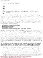
Consider the two-phase motor as shown in Fig. 4.21, where <£a is the
air gap flux created by current flowing in phase a. This flux couples to
phase b in such a way that one-half is coupled in one direction and the
other half is coupled in the opposite direction. Thus the netflux coupled
phase a windings
stator back iron
rotor back iron
Figure 4.21 Mutual coupling between two phases.
phase b winding
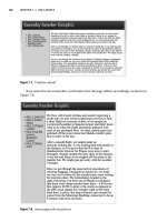
Chapter
r
phase a windings
phase b winding
stator back iron
rotor back iron
Figure 4.22 Mutual coupling among three phases.
to phase b is zero and the air gap mutual inductance is zero. Consequently, the mutual inductance of a two-phase motor has an end turn
contribution only, which is extremely difficult to determine.
For the three-phase case, consider Fig. 4.22. Here the air gap flux
created by current flowing in phase a is coupled to phases b and c such
that two-thirds of the flux is coupled in one direction and one-third is
coupled in the opposite direction. Thus the net flux linked to the other
phases is one-third that linked to phase a itself. Since the self inductance of phase a is linearly related to the flux created by phase a, the
ratio of the air gap mutual and self inductances is one-third (Miller,
1989), i.e.,
M g = -g
(4.25)
By symmetry, this equation applies to all phases of the motor. For
motors with more phases, the mutual inductance is clearly different
between different phases, making the determination of mutual inductance straightforward but more cumbersome.
Winding Resistance
The resistance of a motor winding is composed of two significant components. These components are the slot resistance and the end turn
resistance. Of these two, the slot resistance has a significant ac component, while the end turn resistance does not. Before considering the
ac component, it is beneficial to consider the dc winding resistance.
Brushless Motor Operation
DC resistance
Resistance in general is given by the expression
(4.26)
where lc is the conductor length, Ac is the cross-sectional area of the
conductor, and p is the conductor resistivity. For most conductors, resistivity is a function of temperature that can be linearly approximated
as
p(T2) = p(T0l 1 + ß(T2 - TOI
(4.27)
where p(T\) is the resistivity at a temperature T\, p(T2) is the resistivity
at a temperature T2, and ß is temperature coefficient of resistivity.
For annealed copper commonly used in motor windings, p(20°C) =
1.7241 x 10~8 flm, and ß = 4.3 x 10~3 °C - 1 .
Using (4.26), the slot resistance of a single slot containing ns conductors connected in series is
where L is the slot length, ws and ds are the slot width and height,
respectively, and kcp, the conductor packing factor, is the ratio of crosssectional area occupied by conductors to the entire slot area. Although
at first it doesn't seem appropriate for the resistance to be a function
of the square of the number of turns, (4.28) is correct because there
are ns conductors, each occupying l/ns of the slot cross-sectional area.
As with the end turn inductance, the end turn resistance is a function
of how the end turns are laid out. By making a semicircular end turn
approximation as shown in Fig. 4.20, it is possible to closely approximate the end turn resistance. Inspection of Figs. 4.13, 4.14, and 4.15
shows that the total end turn resistance of the single- and double-layer
winding configurations is equal. While the single layer wave winding
has half as many end turn bundles, it has twice as many turns per
bundle, and the net resistance is essentially the same. Therefore, a
wave winding is assumed in the following calculation of end turn resistance.
Each end turn bundle has ns conductors having a maximum length
of O.ÔTTTp. Thus application of (4.26) gives the approximate resistance
of a single end turn bundle as
=
pTTTpTij
2 kCDwsd.
(4.29)
Chapter
r
A comparison of (4.29) with (4.28) shows that the only difference between the end turn resistance and the slot resistance is the conductor
length. Since the end turns do not contribute to force production but
do dissipate power, it is beneficial to minimize the end turn length.
This is accomplished by maximizing L and minimizing TP. The total
dc resistance of a motor winding is the sum of the slot and end turn
components.
AC resistance
As described in Chap. 2, when conductive material is exposed to an ac
magnetic field, eddy currents are induced in the material in accordance
with Lenz's law. Given the slot magnetic field as described by (4.18)
and as shown in Fig. 4.16, significant eddy currents can be induced in
the slot conductors. The power loss resulting from these eddy currents
appears as an increased resistance in the winding.
To understand this phenomenon, consider a rectangular conductor
as shown in Fig. 4.23. The average eddy current loss in the conductor
due to a sinusoidal magnetic field in the y direction is given approximately by (Hanselman, 1993)
Pec = i
*Lwch?co2ixlH2m
(4.30)
where a = 1/p is the conductor conductivity and Hm is the rms field
intensity value. Since skin depth is defined as
5 =
V «¿IOC
(4.31)
(4.30) can be written as
P. =
Hi
(4.32)
Using this expression it is possible to compute the ac resistance of the
slot conductors. If the slot conductors are distributed uniformly in the
Brushless Motor Operation
slot, substitution of the field intensity, (4.18), into (4.32) and summing
over all ns conductors gives a total slot eddy current loss of
(4.33)
where I is the rms conductor current. Since the power dissipated by a
resistor is PR, the fraction term in (4.33) is the effective eddy current
resistance Rec of the slot conductors. Using (4.28), the total slot resistance can be written as
Rst — Rs + Rec - Rsa
+ Ae)
(4.34)
In this equation, Ae = Rec/Rs is the frequency-dependent term. Using
(4.28) and (4.33), this term simplifies to
(4.35)
This result is somewhat surprising, as it shows that the resistance
increases not only as a function of the ratio of the conductor height to
the skin depth but also as a function of the slot depth to the skin depth.
Thus, to minimize ac losses, it is desirable to minimize the slot depth
as well as the conductor dimension. For a fixed slot cross-sectional
area, this implies that a wide but shallow slot is best. As discussed
earlier, wide slots increase the effective air gap length and increase
the flux density at the base of the stator teeth. Both of these decrease
the performance of the motor. Thus a performance tradeoff is identified.
Armature Reaction
Armature reaction refers to the magnetic field produced by currents
in the stator slots and its interaction with the PMfield. An illustration
of the armature reaction field is shown in Fig. 4.16. Ideally, the magnetic field distribution within the motor is the linear superposition of
the PM and winding magnetic fields. In reality, the presence of saturating ferromagnetic material in the stator can cause these two fields
to interact nonlinearly. When this occurs, the performance of the machine deviates from the ideal case discussed in the above sections. For
example, if the stator teeth are approaching saturation due to the PM
magnetic field alone, then the addition of a significant armature reaction field will thoroughly saturate the stator teeth. This increases
the stator reluctance and the magnet-to-magnet flux leakage, which
drives the PM to a lower PC and lowers the amount of force produced
by the motor.
Chapter
r
In addition to the nonlinear effects described above, the armature
reaction magnetic field determines the movement of the magnet operating point under dynamic operating conditions, as depicted in Fig.
2.20 and repeated in Fig. 4.24. To illustrate this concept, consider Fig.
4.17, where
is the air gap flux due to armature reaction. This flux
is superimposed over the flux emanating from the PM. Dividing this
flux by the area it encompasses gives the armature reactionflux density
Ba, which is easily found as
Bn =
2 (lm + MEg)
(4.36)
Just as the air gap inductance is relatively small for a surface-mounted
PM configuration, Ba is also relatively small. Typically, Ba is in the
neighborhood of 10 percent of the magnet flux density crossing the air
gap. The low recoil permeability and long relative length of the PM
make Ba small. Depending upon the relative position of the coil and
PM, the magnet operating point varies between (Bm - Ba) and {Bm +
Ba).
With reference to Figs. 4.6 and 4.24, operation at (Bm - Ba) occurs
when the rotor and stator are aligned as shown in Fig. 4.6a. Likewise,
operation at (Bm -I- Ba) occurs at an alignment as shown in Fig. 4.6c.
Figure 4.24 Dynamic magnet operation due to coil current.
Brushless Motor Operation
1
Under normal operating conditions, the motor does not reach either of
these extremes because the phase winding is normally not energized
at either extreme. Under fault conditions, however, it is possible for
the operating point to vary much more widely than that shown in the
figure. In particular, if a fault causes the phase current to become
unlimited, the armature reaction flux density (4.36) will increase dramatically and the potential for magnet damage exists.
Of the two extremes, operation at (Bm — Ba) is the most critical since
irreversible demagnetization of the PM is possible if Ba is large and
the PM is operating at an elevated temperature where the demagnetization characteristic has a knee in the second quadrant. In addition
to possible demagnetization, the magnitude of Ba determines the hysteresis loss experienced by the PM. In the process of traversing up and
down the demagnetization characteristic as the rotor moves, the actual
trajectory followed is a minor hysteresis loop. The size of this hysteresis
loop and the losses associated with it are directly proportional to the
magnitude of the deviation in flux density experienced by the PM.
Thus keeping Ba small is beneficial to avoid demagnetization and to
minimize heating due to PM hysteresis loss.
Finally, in addition to the flux density crossing the air gap due to
armature reaction, the slot current also generates a magnetic field
across the slots as described earlier in the discussion of slot leakage
inductance. Of greatest importance is the peak flux density crossing a
slot. Based on Fig. 4.18 and (4.18) the peak flux density leaving the
sides of the slot walls, i.e., the tooth sides, occurs at the slot top and
is given by
1-8 s| max = —
*
(4-37)
Ws
Because flux is continuous just as current is in an electric circuit, this
flux density exists within the tooth tip also. This peak value contributes
to tooth tip saturation, since saturation is a function of the net field
magnitude at the tooth tip, given approximately as [B2S + Bf,)1/2, where
Bg is the air gap flux density.
Conductor Forces
According to the BLi law (3.26), a conductor of length L carrying a
current i experiences a force equal to BLi when it is exposed to a
magnetic field B. Likewise, from (3.23) force is generated that seeks
to maximize inductance when current is held constant. These two phenomena describe torque and force production in motors. In addition
they are useful for describing other forces experienced by the slot-bound
Chapter
r
conductors. In this section the forces experienced by the motor windings
will be discussed. The fundamental question to be resolved is "How
much effort is required to keep the motor windings in the slots?" As
will be shown, little effort is required because the conductors experience forces that seek to keep them there.
Intrawinding force
Since a stator slot contains more than one current-carrying conductor,
the conductors experience a force due to the interaction among the
magnetic fields about the individual conductors. It is relatively easy
to show that when two parallel conductors carry current in the same
direction they are attracted to each other and when the current directions are opposite the conductors repel each other as shown in Fig.
4.25. This follows from the fact discussed in the example in Chap. 2,
whereby the direction of motion is toward the area where the magnetic
fields cancel and away from where they add. Since all conductors in a
slot carry current in the same direction, the slot conductors seek to
compress themselves.
Current induced winding force
Since the windings seek to stay together in a slot, it is important to
discuss the forces that act on the conductors as a whole. One source of
force is the current in the winding itself. Given the discussion of slot
leakage inductance and the fact that force always acts to increase
inductance, it is apparent that the winding as a whole experiences a
force that drives the winding to the bottom of the stator slot. This force
is easily understood by considering what happens to the slot leakage
inductance if the winding is pulled partway out of the slot as shown
in Fig. 4.26. In this case the bottom of the slot contributes nothing to
the slot inductance and the magnetic field at the top of the winding is
no longer focused by the slot walls. Both of these decrease the slot
leakage inductance, and thus the winding as a whole must experience
a force that draws the winding into the slot. An expression for the
Figure 4.25 Force between current-carrying conductors.
Brushless Motor Operation
Figure 4.26 A winding partially
removed from a slot.
Stator Back Iron
magnitude of this force can be found in Gogue and Stupak (1991) and
Hague (1962).
Permanent-magnet induced winding force
As derived from the Lorentz force equation, the BLi rule implies that
the force generated by the construction shown in Fig. 4.1 is between
the PM magnetic field and the current-carrying conductors in the slots.
While this interpretation gives the correct result that agrees with the
macroscopic approach, the burying of conductors in slots transfers the
force to the slot walls (Gogue and Stupak, 1991). That is, the conductors
themselves do not experience the force generated by the PMs, but
rather the steel teeth between the slots feel the pull. As a result, the
windings are not drawn out of the slots by the PMs.
Summary
To summarize, when windings appear in the slots in a motor, they do
not experience any great force trying to pull them out. On the contrary,
current flow in the conductors promotes their cohesion and generates
a force driving them away from the slot opening, toward the slot bottom.
Cogging Force
In the force derivation considered earlier, only the mutual or alignment
force component was considered. In an actual motor, force is generated
due to both reluctance and alignment components as described by Eq.
(3.24) for the rotational case. For the translational case considered
here, (3.24) can be rewritten as
(4.38)
The last term in (4.38) is identical to (3.27) and is the alignment force
of the linear motor. The first two terms in (4.38) are reluctance com-
4
Chapter
r
ponents for the coil and magnet, respectively. Since these reluctance
forces are not produced intentionally, they represent forces that must
be eliminated or at least minimized so that ripple-free force can be
produced.
The first term in (4.38) is due to the variation of the coil self inductance with position. Based on the analysis conducted earlier, the
coil self inductance is constant. Therefore, the first term in (4.38) is
zero, leaving the second term in (4.38) as the only reluctance force
component. Because of its significance, this force is called cogging force
and is identified as
where (f>g is the air gap flux and R is the net reluctance seen by the
flux (f)g. The primary component of R is the air gap reluctance Rg.
Therefore, if the air gap reluctance varies with position, cogging force
will be generated. Based on this equation, cogging force is eliminated
if either 4>g is zero or the variation in the air gap reluctance as a function
of position is zero. Of these two, setting (})g to zero is not possible since
4>g must be maximized to produce the desired motor alignment force.
Thus cogging force can only be eliminated by making the air gap
reluctance constant with respect to position. In the next chapter, techniques for cogging force reduction will be considered in depth.
On an intuitive level, cogging force is easy to understand by considering Fig. 4.27. In this figure, the rotor magnet is aligned with a
maximum amount of stator teeth and the reluctance seen by the magnet flux is minimized, giving a maximum inductance. If the magnet is
moved slightly in either direction, the reluctance increases because
more air appears in the flux path between the magnet and stator back
Stator Back Iron
Figure 4.27 Cogging force due to slotting.
Brushless Motor Operation
iron. This increase in reluctance generates a force according to (4.39)
that pushes the magnet back into the alignment shown in the figure.
This phenomenon was first discussed in Chap. 1, where a rotating
magnet seeks alignment with stator poles as shown in Fig. 1.6.
Rotor-Stator Attraction
In addition to the %-direction alignment and cogging forces experienced
by the rotor, rotor-stator attractive force is also created by the topology
shown in Fig. 4.1. That is, an attractive force is generated that attempts
to close the air gap and bring the rotor and stator into contact with
each other. This force is given by an expression similar to the cogging
force expression (4.39),
F =
2
8
dg
In this situation, however, the force is proportional to the rate of change
of the air gap permeance with respect to the air gap length. By assuming that the air gap permeance is modeled as Pg = ixQAg/g, the above
equation can be simplified to give the attractive force per square meter
as
B2
frs = TT2M
o
(4.40)
where Bg is the air gap flux density.
The force density given by (4.40) is substantial. In applications, the
rotor and stator are held apart mechanically. Thus, in some motor
topologies, this force creates mechanical stress that must be taken into
account in the design. However, in many topologies, this force is balanced by an equal and opposite attractive force due to symmetry. In
this case, the mechanical stress is ideally zero but in reality is greatly
reduced.
Core Loss
The power dissipated by core loss in the motor is due to the changing
magnetic field distribution in the stator teeth and back iron as the
rotor moves relative to the stator and as current is applied to the stator
slots. Since the magnetic field in the rotor is essentially constant with
respect to time and position, it experiences no core loss. The amount
of core loss dissipated can be computed in a number of different ways
depending upon the desired modeling complexity. The simplest method
Chapter
r
is to assume that the flux density in the entire stator volume experiences a sinusoidal flux density distribution at the fundamental electrical frequency fe. In this case, the core loss is
Pel = PsVsTbi
(4.41)
where ps is the mass density of the stator material, V s is the stator
volume, and Tbi is the core loss density of the stator back iron material.
This last parameter is a function of the peak flux density experienced
by the material as well as the frequency of its variation. As discussed
in Chap. 2, this parameter is often given graphically, as shown in Fig.
2.15.
A second approach is to consider the stator teeth and back iron
separately, since they typically experience a different peakflux density.
Given an estimate of these flux densities, (4.41) is applied to each
partial volume separately and the results summed to give the total
core loss.
Yet another method takes an even more rigorous approach (Slemon
and Liu, 1990). Likk the last approach, the stator teeth and back iron
are considered separately. However, in this approach the hysteresis
and eddy current components are considered separately. In addition,
theflux density distribution is not assumed to be sinusoidal, but rather
as a piecewise linear function determined by the motor geometry. Because of the significant development required, this method will not be
developed here.
Summary
This concludes the presentation of the basic theory of brushless PM
motor operation and the computation of fundamental parameters. The
analysis presented in the above sections provides a basis for the design
of actual brushless PM motors. By simple coordinate changes, the analysis applies to both axial and radial motors. For axial motors, the
magnets are positioned to direct flux in an axial direction interacting
with radial, current-carrying slots. As stated earlier, this conforms to
the requirements of the Lorentz force equation for the generation of
circumferential force, or torque. In radial motors, the directions of the
magnet flux and current are switched. Magnet flux is directed radially
across an air gap to interact with current in axially oriented slots.
Fundamental Design Issues
Before discussing specific motor topologies, it is beneficial to discuss
fundamental design issues that are common to all topologies. These
issues revolve around the motor force equation, (4.15), which is illus-
Brushless Motor Operation
trated in Fig. 4.28. In addition, the product nsi in (4.15) is recognized
as the total slot current and is replaced by I s .
Each term in the force expression in Fig. 4.28 has fundamental implications which are issues to be considered in the design of brushless
PM motors. In the following, the significance of each term is discussed.
Air gap flux density
Increasing the air gap flux density increases the force generated. The
amount of flux density improvement achievable is limited by the ability
of the stator teeth to pass the flux without excessive saturation. Any
increase in the flux density requires an increase in the PC of the
magnetic circuit or the use of a magnet with a higher remanence.
Increasing the PC implies increasing the magnet length or decreasing
the effective air gap length. Manufacturing tolerances do not allow the
physical air gap length to get much smaller than approximately 0.3
mm (0.012 in). In addition, decreasing the air gap length increases the
cogging force.
Active motor length
The active motor length can be increased to improve the force generated. However, doing so increases the mass and volume of the motor.
A further consequence is that the resistive loss also increases, since
longer slots require longer wire. Therefore, increasing the motor active
length does not improve power density or efficiency. As a result, motor
length is often chosen as the minimum value required to meet a given
force specification.
Number of magnet poles
Increasing the number of magnet poles increases the force generated
by the motor. Increasing the number of poles in a fixed area implies
decreasing the magnet width to accommodate the additional magnets.
Number
of Magnet
Poles
Active
Motor
Length
Peak
Force
p
-
AT R
Air Gap
Flux Density
TT
Figure 4.28 The permanent magnet motor force equation.
Slot
Current
Chapter
r
This increases the relative amount of magnet leakage flux, causing kmI
to increase, which in turn decreases the air gap flux density (4.12).
Thus the increase in force does not increase indefinitely. Sooner or
later the force will actually decrease with an increase in magnet poles.
This implies that there is some optimum number of magnet poles.
In addition to its effect on the magnet leakage, an increase in the
number of magnet poles decreases the motor pole pitch, which corresponds to shorter end turns. In turn, this implies that the end turn
resistive loss and leakage inductance are minimized. All of these consequences are beneficial. Shorter end turns lead to less resistive loss,
which increases efficiency and decreases the thermal management burden. The decreased inductance makes the motor easier to drive.
A further consequence of increasing the number of magnet poles is
that the motor drive frequency is directly proportional to the number
of poles by (1.3). This increase in the drive frequency increases the core
loss in the motor since the flux in the ferromagnetic portions of the
motor alternates direction at the drive frequency. This tends to decrease the motor and drive efficiency.
Yet another consequence of increasing the number of magnet poles
is that the required rotor and stator back iron thickness decreases.
This occurs because as the magnets become narrower the amount of
flux to be passed by the back iron decreases.
To summarize, increasing the number of magnet poles is beneficial
up to the point where magnet leakage flux, core loss, and drive frequency requirements begin to have a significant detrimental effect on
motor performance.
Slot current
The total slot current is the last term contributing to the motor force.
Since the slot current is the product of the number of turns per slot
and the current per turn, the effect of the slot current can be assessed
by considering each component.
Inductance increases as the square of ns; therefore, the motor becomes more difficult to drive as ns increases. On the other hand, for a
given motor force, an increase in n s can be coupled with a decrease in
conductor current. This decreases the resistive winding loss, which
increases the motor efficiency.
Increasing the number of turns per slot while holding the current
per turn constant will increase the generated force. If the conductor
size is constant, the slot cross-sectional area grows as ns increases. This
increase in slot area increases the slot fraction and the mass of the
stator back iron, both of which have a detrimental effect on power
density.
Brushless Motor Operation
Increasing the slot current increases the armature reaction field.
This increases the core loss in the magnets and potentially decreases
the air gapflux density due to stator saturation. In addition, increasing
the slot current while holding the slot cross-sectional area fixed increases the current density, which increases the resistive winding loss.
Electric versus magnetic loading
In the above discussion, the fundamental conflict between a high air
gap flux density and a high slot current appears in a number of the
arguments. If one gets too high, the other must decrease. For example,
as the current increases, more slot area is required to maintain constant resistive loss and the maximum air gap flux density decreases.
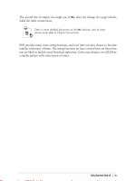
This tradeoff can be visualized by considering Fig. 4.29, where the
maximum air gap flux density and slot current are plotted vs. the slot
fraction. In Fig. 4.29, the maximum air gap flux density decreases as
the slot width increases because magnetic saturation limits the flux
carrying capacity of the teeth. Likewise, the maximum slot current
increases with increasing slot width. Since the force generated is a
function of the product of the flux density and slot current, maximum
force is generated when the slot fraction is somewhere near one-half
(Sebastian, Slemon, and Rahman, 1986).
Dual Air Gap Motor Construction
In high power density motor design, the goal is to circumvent or improve the tradeoff between electrical and magnetic loading by finding
a way to increase one in a manner that does not diminish the other.
One simple method of doubling the current without decreasing the air
gap flux density is to employ double air gap construction as shown in
Fig. 4.30.
>
\4~
<-
0
Slot Fraction, a = w /r,
T
s
->
1
Figure 4.29 Magnetic vs. electric loading as a function of slot fraction.
Chapter
r
Figure 4.30 Preferable dual air gap construction.
Comparing this figure with the single air gap case in Fig. 4.1, this
construction replaces the rotor back iron with a second air gap and a
second stator. By doing so, the magnet flux on the opposite side of the
magnets, which was not used to produce force before, is now used to
produce force by interacting with slot current on the lower stator. In
essence, the available slot area has doubled without changing the original air gap and stator back iron. This construction doubles the force
generated because it has twice as many current-carrying turns. However, it does not significantly change the overall motor efficiency, as
the resistive losses have doubled also. The power density of the dual
air gap motor is greater but not double that of the single air gap motor.
While the rotor back iron is replaced with another stator of approximately the same mass, the magnet length in the dual air gap motor
must be twice that of the single air gap motor to maintain the same
magnetic operating point or PC. Thus the doubling of the magnet mass
keeps the dual air gap motor from achieving twice the power density.
In terms of thermal performance, this construction does not differ from
the single air gap case. By adding a second stator back iron, the area
available for heat removal doubles with the doubling in slots.
Inspection of Fig. 4.30 shows that the rotor is male and the stators
as a whole are female. With this in mind, it is possible to conjecture
that the complementary situation, i.e., a male stator and female rotor,
may offer the same performance improvement. This construction, depicted in Fig. 4.31, clearly suffers in a number of ways. First, the
amount of back iron required is high, which eliminates the power
density improvement achieved with the construction shown in Fig.
4.30. Perhaps more importantly, by having the stator sandwiched between the two rotors, heat removal is much more difficult. In Fig. 4.31,
the heat-producing stators are separated and on the outside, where
heat removal is more easily accomplished. In the alternate construc-
Brushless Motor Operation
101
Figure 4.31 Less desirable dual air gap construction.
tion, however, all the heat-producing windings are concentrated in one
area and that area is isolated from the motor frame.
Despite the weaknesses of the alternate construction, one manufacturer has built motors utilizing this topology (Huang, Anderson, and
Fuchs, 1990). To reduce the motor mass and regain power density, they
removed the stator back iron. While this does make the alternate construction comparable in mass with the preferred construction shown
in Fig. 4.30, removal of the stator back iron has two major consequences. The primary consequence is that heat removal from the stator
is even more difficult because the high thermal conductivity of the
stator back iron has been replaced with potting material of lower thermal conductivity. In addition, the magnet length and thus mass must
be increased because the lack of stator back iron increases the effective
air gap and dramatically reduces the PC.
Summary
This concludes the discussion of brushless motor operation. In this
chapter, basic assumptions were presented to define and focus the discussion toward the fundamental features of brushless PM motors. For
simplicity and generality, basic motor operation was discussed in terms
of a linear translational motor. From this information, fundamental
design issues were identified and dual air gap construction was discussed as a way to maximize power density. Given this body of information, it is now possible to discuss common design variations.
Chapter
5
Design Variations
Brushless motors are seldom designed as described in Chap. 4. N u merous minor and sometimes major differences are implemented in
actual motors to improve their performance in a variety of ways depending on the intended application. In this chapter, many design
variations will be illustrated. Since the cylindrical, radial flux motor
configuration appears so frequently, it will be used to illustrate the
points made in this chapter. It is important to note that all possible
design variations are not described here. There are an infinite number
of variations resulting from an infinite number of assumptions and
performance tradeoffs. Many of these variations are the result of years
of engineering effort and insight. As a result, this chapter considers
only common design variations. Based on these, the fundamental properties of most design variations can be determined.
Rotor Variations
In Chap. 4, the rotor magnets alternated in polarity and appeared at
the rotor surface. While this is a popular configuration, certainly others
are possible, as shown in Fig. 5.1. In all cases, the rotor's purpose is
to provide the magnetic field B for the BLi law (3.26). Cost is usually
the determining factor in the choice of rotor construction. Permanentmagnet material and the handling of PMs represent a major cost item
in the construction of brushless PM motors. Therefore, it is not uncommon to choose a less expensive rotor design, even if it leads to lower
performance.
In Fig. 5.1a, every other magnet is replaced with an extension of the
rotor back iron. Essentially, theflux from the inner south magnet poles
is wrapped around to become the adjacent magnet pole at the rotor
surface. This consequent pole design (Hendershot, 1991) reduces the
103
Chapter
e
O
N
(a)
(b)
N
Figure 5.1 Rotor design variations.
S
Design Variations
105
number of magnets by one-half but requires the remaining magnets
to be longer to maintain a sufficient PC. This rotor construction offers
no performance enhancement but can be less expensive to produce since
the number of magnets is cut by one-half. The most important magnetic
difference in this configuration is that the air gap inductance is now
a function of position since the permeability of the consequent poles is
much greater than that of the magnets. This variation can lead to a
substantial reluctance torque.
Figure 5.16 illustrates a popular form of an interior PM rotor. Here
the magnets appear orthogonal to the air gap, rather than facing it,
and the magnet flux is directed to the air gap through electrical steel.
The primary reason for this structure is that flux concentration is
possible if the surface area of the magnets exceeds that of the block of
steel at the air gap. This configuration is popular when higher performance is desired when using inexpensive ferrite magnets. As with
Fig. 5.1a, the air gap inductance is now at least a small function of
rotor position.
In Fig. 5.1c, the nonmagnetic spacer between the magnets is replaced
by electrical steel. The purpose of this steel is to add a reluctance torque
component to the motor output. If designed properly, a significant improvement in motor output is possible (Sebastian and Slemon, 1987).
Based on the figure, one might think that the steel spacers act to divert
substantial magnet flux away from the air gap. This is not true, however, because magnets have an anisotropic permeability that gives
them a very low permeability perpendicular to the direction of magnetization.
Figure 5.1 d shows a rotor with no spacers at all. In this case, the
rotor is constructed from a single piece of bonded magnet material,
which is magnetized with alternating magnet poles to mimic the basic
configuration considered originally. The primary advantage of this construction is its very low cost. With the low cost comes the low relative
performance of bonded magnetic material.
Finally, Fig. 5.1 e,f show two common variations of the surfacemounted magnet configuration considered in Chap. 4. Figure 5.1e
shows loaf-shaped magnets and Fig. 5.1/shows magnets with parallel
sides. Both of these variations exist as potentially cheaper alternatives
to the more ideal radial arc magnet shown in Fig. 2.22.
Analysis of a motor having any of these rotor constructions follows
the same general approach as that described in Chap. 4. Any even
number of rotor magnets can be used. Once a suitable magnetic circuit
model for the rotor is found, all parameters and performance specifications can be computed. Under most circumstances, the rotor is
modeled by an equivalent radial arc magnet and the analysis conducted
in Chap. 4 is directly applied.
Chapter
e
Stator Variations
Compared with rotor variations, variations in stator construction are
much more numerous and common. Some typical variations are shown
in Fig. 5.2. In all cases, the stator's purpose is to guide the air gap flux
past the stator windings that carry the current i for the BLi law.
Figure 5.2 Stator design variations.
Design Variations
107
Figure 5.2a shows the salient-pole or solenoidal-winding construction discussed in Chap. 1. A benefit of this construction is short end
turns since windings are formed around individual poles. In addition,
there is usually less coupling between phases. The disadvantage of this
construction is that each phase winding does not interact simultaneously with all rotor magnets, which can lead to lower performance.
Eliminating the slots altogether and distributing the stator windings
inside the stator back iron gives the slotless construction shown in Fig.
5.26. This construction exhibits no cogging torque but does have several
disadvantages. First, although there is more room for windings in this
construction, the electrical loading cannot be increased substantially
because the thermal conductivity between the windings and the back
of the stator back iron is much lower. Thus it is more difficult to remove
the heat produced by the windings. Second, the lack of stator teeth
makes the effective air gap length equal to the distance from the rotor
surface to the stator back iron. Therefore, to maintain a sufficient PC,
the magnet length must grow substantially.
Figure 5.2c shows a slotted structure similar to that considered in
Chap. 4. Here, however, the slots are not rectangular but rather have
shoes on them at the air gap. The purpose of these shoes is to reduce
the variation in air gap permeance as a function of position, thereby
reducing cogging torque. This construction is so common that it will
be discussed at length.
Shoes and Teeth
As mentioned above, the purpose of the shoes is to make the air gap
appear to have a uniform permeability as a function of position. As
could be expected, there are numerous tradeoffs involved in shoe design. To illustrate these tradeoffs, consider a typical slot and shoe cross
section as shown in Fig. 5.3, where the slot conductors are assumed to
fill the rectangular portion of the slot. In those cases where the conductor area is trapezoidal as shown in Fig. 5.2c, approximating it by
an equivalent rectangular area usually leads to little error. Similar to
Fig. 4.16, Fig. 5.3a shows the magnetic field produced due to slot current, i.e., the armature reactionfield. Figure 5.3b identifies parameters
associated with slot, tooth, and shoe geometry.
Because of the presence of shoes, ws is much smaller than the slot
width at the slot bottom wsb, which was the slot width considered in
Chap. 4. As a result, the Carter coefficient is smaller than that discussed earlier. More importantly, the shoe area increases the slot leakage inductance. Here the slot leakage inductance has three components, the distributed inductance computed earlier (4.19), the
inductance of the area leading to the shoe tip, and the inductance of
Chapter
e
Stator Back Iron
(a)
N
T
5
•)
Ubi
(b)
Figure 5.3 (a) Magneticfield distribution due to coil current, and (6)
associated slot geometry.
Design Variations
109
the shoe tip area. Using the inductance expression (3.3) to describe
these additional areas, the total slot leakage inductance becomes
^PD3L
3 wsb
+
FX0d2L
(ws + wsb)/2
+
/XPDJL
ws
(5.1)
where L is the depth of the slot into the page and n s is the number of
turns in the slot. The terms inside the brackets in (5.1) are the respective permeances of the three slot areas. The first term represents
the conductor area previously derived in (4.19). The second term approximates the sloping area as a rectangular area having height d2
and average width (ws + wsbV2, and the third term is the permeance
of the shoe tip area. In some texts, /JL0L is factored out and the terms
remaining inside the brackets are called slot constants (Nasar, 1987)
or normalized permeances (Liwschitz-Garik and Whipple, 1961).
Clearly, if ws is made very small (just large enough to slide a single
conductor through), the third term in (5.1) can dominate the slot leakage inductance, making the phase inductance large. This high inductance is a mixed blessing. Under fault conditions, a high inductance
limits the rate of change in current since dildt = v/L, where v is the
fault voltage and L is inductance. This increases the amount of time
available for any fault-detection circuitry to respond to the fault. At
the same time, high inductance makes the motor harder to drive because the rate at which current can be built up in a winding is limited
by the same basic phenomenon. As a result, a tradeoff exists. As ws
decreases, the air gap permeance variation decreases, but the slot leakage inductance increases.
The value of the shoe tips depends on the high permeability of the
ferromagnetic material composing the shoes and teeth. As the shoe tip
becomes saturated, the uniformity of the air gap permeance deteriorates. In the worst case, the shoe tips become so saturated that they
essentially appear as air, in which case they serve no benefit whatsoever. As discussed in the armature reaction section of Chap. 4, the
air gap flux and the slot leakage flux both contribute to shoe saturation.
Here the air gap flux density Bg enters the tooth-shoe face from the
air gap and the slot leakageflux crosses from shoe to shoe perpendicular
to the air gap, as shown in Fig. 5-3a. Because of flux continuity the
net field magnitude within the shoe tip is (Bf + Bf) 1/2 , where Bs is the
peak slot leakage flux density given by (4.37). With reference to (4.37),
Bs is inversely proportional to ws; thus making ws small also increases
the likelihood of shoe tip saturation. While it is not clear from this
analysis, the shoe depth di + d2 is also important to minimize saturation. Intuitively, <¿1 + d2 must be large enough so that the air gap
flux entering the shoe tip does not have to turn sharply to proceed