Microsoft XNA Game Studio Creator’s Guide- P6 docx
Bạn đang xem bản rút gọn của tài liệu. Xem và tải ngay bản đầy đủ của tài liệu tại đây (367.55 KB, 30 trang )
T
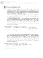
EXTURE COLORING
It is possible to color your image textures at run time. This technique might be handy
for a number of instances—maybe you need your texture to be darker and you can’t
wait for the artist to fix it, so you decide to shade it in your code. Maybe you want to
create a stone pattern; you could use the same image to draw all stones but alternate
the shade to create more contrast on the surface.
The Texture.fx shader is already able to apply colors, which are stored in the verti-
ces, to any textured item. If a non-white color is stored in the vertices, the image in the
texture will be shaded by this color.
To demonstrate how this works, it helps to examine the vertex shader and pixel
shader. The vertex shader input receives the color stored in the vertices. The user-de-
fined struct that stores the vertex shader output stores this color information. The
vertex shader output, by design, serves as the input for the pixel shader. This vertex
shader code receives the color from the vertices that are set in your C# code and
passes it to the pixel shader:
void VertexShader(in VSinput IN, out VStoPS OUT){
OUT.position = mul(IN.position, wvpMatrix); // transform object
// orient it in viewer
OUT.color = IN.color; // send color to p.s.
OUT.uv = IN.uv; // send uv's to p.s.
}
The pixel shader can only return colored pixels as output. On the first line of the
shader, the texture is applied to each vertex using the tex2D() function, which uses
the textureSampler filter and UV coordinates as input parameters. The pixel
shader uses linear interpolation to shade and texture the area between the vertices.
On the second line, this optional instruction is added, which multiplies the colored
pixel by the color that is stored in the vertices. This modification, in effect, applies a
color to the image texture:
void PixelShader(in vsOutput IN, out psOutput OUT)
{ // apply texture to vertices using textureSampler filter
OUT.color = tex2D(textureSampler, IN.uv);
// apply color from v.s. – p.s. interpolates between verts
OUT.color *= IN.color;
}
MICROSOFT XNA GAME STUDIO CREATOR’S GUIDE
128
129
Texture Example
This example begins with either the MGHWinBaseCode project or the
MGH360BaseCode project, which can be found at the BaseCode folder on this
book’s website. This project already has textured ground and uses the Texture.fx file
described earlier in this chapter. Aside from the shader already being present, this
demonstration shows how to add in new textured objects from scratch. This demon-
strates the texturing process from start to finish. Each surface will be transformed
into place, and the accompanying textures will be applied to each of them. Part A of
this example demonstrates how to add in the ground that is used in the base code. By
the time Part B of this example is complete, a textured side wall and a textured back
will also be visible.
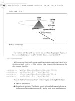
In Part C of this example, a tree texture with transparency will be added. This tree
will use a “billboarding” technique, which allows it to always face the viewer—re-
gardless of the camera’s angle. Figure 9-3 shows the billboard tree from different
camera angles.
CHAPTER 9
Texturing Your Game World
FIGURE 9-3
Billboarding applied to tree so it always faces viewer
Texture Example, Part A: Adding
the Grass Texture
To demonstrate how to load an opaque texture into any 3D game project, and to
draw it, Part A of this example will include adding the grass texture that is used in the
base code. If you are following the “Building the Base Code from Scratch” example
from Chapter 17, you will need to follow the steps in this section. If you are working
through this chapter and have already started with the MGHWinBaseCode project
or the MGH360BaseCode project, you can skip this section and go to Part B. How-
ever, if you are reading Chapter 9 for the first time, you should probably still read this
section so that you can understand how the texture is set up from the very beginning.
When you are applying textures in a 3D game, you require a shader that can han-
dle the texture-mapping data. The Texture.fx code presented earlier in this chapter
can do the job. This shader must be referenced from the Content node of your game
project. You can find the Texture.fx file in the Shaders folder on this book’s website.
To keep your different project files organized, create a Shaders folder under the Con-
tent node and add your Texture.fx shader file there. In Figure 9-4, you can see your
Texture.fx file referenced from the Solution Explorer.
At the top of the game class, you require an Effect object to load and access
your shader. EffectParameter objects are also required to allow you to
set values in your shader from your C# game code. In this case, you will need
two EffectParameter objects. The first EffectParameter,
textureEffectWVP, allows you to define how your world will be seen by your
MICROSOFT XNA GAME STUDIO CREATOR’S GUIDE
130
FIGURE 9-4
Shader reference in the Solution Explorer
131
camera. The second EffectParameter, textureEffectImage, allows you to
set the texture that is applied against surfaces that are drawn from the shader:
Effect textureEffect; // shader object
EffectParameter textureEffectWVP; // cumulative matrix w*v*p
EffectParameter textureEffectImage; // texture parameter
The Microsoft XNA game project template automatically generates a folder
named “Content” for loading your shaders and media. Also, the project template au-
tomatically adds a line of code to set the Content.RootDirectory property to
this directory. To load your texture shader when the program begins, and to set your
game project references to the shader’s camera settings and texture variables, add
these instructions to the InitializeBaseCode() method:
textureEffect = Content.Load<Effect>("Shaders\\Texture");
textureEffectWVP = textureEffect.Parameters["wvpMatrix"];
textureEffectImage = textureEffect.Parameters["textureImage"];
When drawing objects that have textures, the GraphicsDevice needs to re-
trieve data from the vertex variable in the proper format. A new
VertexDeclaration object is declared in the module declarations section so that
the graphics device can later retrieve the correct position, color, and UV data.
private VertexDeclaration positionColorTexture;
Later, in the InitializeBaseCode() method, you need more code to set the
VertexDeclaration object to store the VertexPositionColorTexture
type:
positionColorTexture = new VertexDeclaration(graphics.GraphicsDevice,
VertexPositionColorTexture.VertexElements);
As you have seen when you run the base code, the ground is created using a square
surface that is covered with a grass texture. The sides of the square are set to have the
length equivalent to the constant BOUNDARY. If you are building the base code, a dec-
laration for BOUNDARY is required at the top of the game class:
private const float BOUNDARY = 16.0f;
A Texture2D object is required to load and access the image file at run time, so a
declaration for the texture object is also needed at the top of the game project:
private Texture2D grassTexture;
CHAPTER 9
Texturing Your Game World
MICROSOFT XNA GAME STUDIO CREATOR’S GUIDE
132
The grass.jpg image will be used to texture the ground. This file can be found in the
Images folder in the download for this book. It is loaded in your project using the
Load() method when the program begins. The code here works under the assump-
tion that you have created an Images folder under the Content node in the Solution
Explorer and you have copied the grass.jpg file to the Images folder, so it is referenced
from there. To create an Images folder, right-click the Content node in the Solution
Explorer and then click Add New Folder. To reference the image file from there,
right-click the Images folder, select Add, and then navigate to the grass.jpg file and
select it. Add this instruction to load the grass texture inside the LoadContent()
method:
grassTexture = Content.Load<Texture2D>("Images\\grass");
You will need an array of vertices to store the position, color, and UV tex-
ture-mapping data. The declaration is made at the top of the game class so it can be
initialized and then used for drawing the ground.
VertexPositionColorTexture[] groundVertices = new
VertexPositionColorTexture[4];
Next, add InitializeGround() to the game class to store the vertices with po-
sition, color, and UV coordinates. For the ground vertices, the UV coordinates are set
to tile the image ten times along the horizontal and vertical. The image has been de-
signed specifically to create a repeating pattern that is not easily detected by the na-
ked eye. Tiling the image allows it to be drawn with a higher resolution of detail.
private void InitializeGround(){
const float BORDER = BOUNDARY;
Vector2 uv = new Vector2(0.0f, 0.0f);
Vector3 pos = new Vector3(0.0f, 0.0f, 0.0f);
Color color = Color.White;
// top left
uv.X= 0.0f; uv.Y= 0.0f; pos.X=-BORDER; pos.Y=0.0f; pos.Z=-BORDER;
groundVertices[0] = new VertexPositionColorTexture(pos, color, uv);
// bottom left
uv.X= 0.0f; uv.Y=10.0f; pos.X=-BORDER; pos.Y=0.0f; pos.Z=BORDER;
groundVertices[1] = new VertexPositionColorTexture(pos, color, uv);
// top right
uv.X=10.0f; uv.Y= 0.0f; pos.X= BORDER; pos.Y=0.0f; pos.Z=-BORDER;
groundVertices[2] = new VertexPositionColorTexture(pos, color, uv);
// bottom right
133
CHAPTER 9
Texturing Your Game World
uv.X=10.0f; uv.Y=10.0f; pos.X= BORDER; pos.Y=0.0f; pos.Z=BORDER;
groundVertices[3] = new VertexPositionColorTexture(pos, color, uv);
}
To set up the ground vertices when the program begins, add the call to
InitializeGround() inside Initialize():
InitializeGround();
When rendering the new textured surfaces, you need to select the correct shader, but
it is possible to use more than one shader for drawing. Just be certain of two things:
When an effect is selected, all code for rendering should be triggered
between the texture shader effect’s Begin() and End() methods.
The shader effect’s End() method must be executed before another shader
effect begins.
When you are setting parameters in the shader, the more performance-friendly
and common approach is to set these parameters before Begin() is called for the
Effect object. Effect.Begin() sets all of the render states. However, if you
need to set an effect parameter after Begin(), you would need to finalize this state
by calling Effect.CommitChanges() or it will not be set.
While the shader is active, you can then specify the vertex type and
call DrawUserPrimitives() to draw your textured surface.
DrawUserPrimitives() in this case must specify a textured vertex type. Then the
primitive type, vertices, vertex offset, and number of primitive objects are supplied as
parameters to this method. Add TextureShader() to your game class to trigger
use of the Texture.fx shader and to draw your textured objects with it. If you are us-
ing a prebuilt version of the base code, this project already contains this method:
private void TextureShader(PrimitiveType primitiveType,
VertexPositionColorTexture[] vertexData, int numPrimitives){
textureEffect.Begin(); // begin using Texture.fx
textureEffect.Techniques[0].Passes[0].Begin();
// set drawing format and vertex data then draw surface
graphics.GraphicsDevice.VertexDeclaration = positionColorTexture;
graphics.GraphicsDevice.DrawUserPrimitives
<VertexPositionColorTexture>(
primitiveType, vertexData, 0, numPrimitives);
textureEffect.Techniques[0].Passes[0].End();
textureEffect.End(); // stop using Textured.fx
}
MICROSOFT XNA GAME STUDIO CREATOR’S GUIDE
134
The code needed to draw textured surfaces, like your grass-covered ground, fol-
lows the same steps that are taken when drawing surfaces with only color and posi-
tion coordinates. The main differences are in step 4 and step 5. In step 4, an
EffectParameter object is used to assign a texture in the shader. In step 5, the
TextureShader() routine is called to select the appropriate shader and to draw
with it. Add DrawGround() to your game class to implement this routine:
private void DrawGround(){
// 1: declare matrices
Matrix world, translation;
// 2: initialize matrices
translation = Matrix.CreateTranslation(0.0f, 0.0f, 0.0f);
// 3: build cumulative world matrix using I.S.R.O.T. sequence
// identity, scale, rotate, orbit(translate & rotate), translate
world = translation;
// 4: set shader parameters
textureEffectWVP.SetValue(world*cam.viewMatrix*cam.projectionMatrix);
textureEffectImage.SetValue(grassTexture);
// 5: draw object - primitive type, vertex data, # primitives
TextureShader(PrimitiveType.TriangleStrip, groundVertices, 2);
}
To trigger the drawing, DrawGround() must be called from inside Draw():
DrawGround();
If you are working through the Chapter 17 exercise, “Building the Base Code from
Scratch,” and have completed these steps, you are now done adding all of the code re-
quired for texturing your surfaces. You can view your textured ground when you run
the project now.
Texture Example, Part B: Adding Two More
Opaque Textures
In this next portion of the example, two wall textures will be applied to the surfaces
to create a side wall and back wall. To store the new wall images, you will require
Texture2D objects, so declarations are needed for the wall textures in the game
class declarations area:
private Texture2D backWallTexture, sideWallTexture;
135
CHAPTER 9
Texturing Your Game World
The backwall.jpg and sidewall.jpg images will be used to texture both walls. They
can be found in the Images folder on this book’s website. They are loaded in your
project using the Load() method when the program begins. Add these two image
files to the Content\Images directory of your project and add them to your project us-
ing the Solution Explorer. If the Images folder does not exist, right-click the Content
node in your game project and select Add | New Folder to launch the dialog that al-
lows you to add an Images folder. Then, once you have an Images folder under the
Content node, right-click it, select Add, and then navigate and select each of the im-
age files. Add these instructions to load each texture inside the LoadContent()
method:
backWallTexture = Content.Load<Texture2D>("Images\\backwall");
sideWallTexture = Content.Load<Texture2D>("Images\\sidewall");
The vertices used to draw the walls store position, color, and UV coordinates to
map the images onto this surface. An array of VertexPositionColorTexture
coordinates is needed:
private VertexPositionColorTexture[] surfaceVertex = new
VertexPositionColorTexture[4];
The method InitializeSurface() initializes the vertices with the position,
color, and UV coordinates that you will use to create a rectangular surface for each
wall. The UV coordinates will be mapped with U along the X axis and with V along
the Z axis.
Add InitializeSurface() to the game class to create these vertices with po-
sition, color, and UV coordinates:
private void InitializeSurface(){
Vector2 uv = new Vector2(0.0f, 0.0f);
Vector3 pos = new Vector3(0.0f, 0.0f, 0.0f);
Color color = Color.White;
// A. top left, B. bottom left, C. top right, D. bottom right
uv.X=0.0f; uv.Y=0.0f; pos.X=-BOUNDARY; pos.Y=0.0f; pos.Z=-BOUNDARY;
surfaceVertex[0] = new VertexPositionColorTexture(pos, color, uv);//A
uv.X=0.0f; uv.Y=1.0f; pos.X=-BOUNDARY; pos.Y=0.0f; pos.Z=BOUNDARY;
surfaceVertex[1] = new VertexPositionColorTexture(pos, color, uv);//B
uv.X=1.0f; uv.Y=0.0f; pos.X=BOUNDARY; pos.Y=0.0f; pos.Z=-BOUNDARY;
surfaceVertex[2] = new VertexPositionColorTexture(pos, color, uv);//C
uv.X=1.0f; uv.Y=1.0f; pos.X=BOUNDARY; pos.Y=0.0f; pos.Z=BOUNDARY;
surfaceVertex[3] = new VertexPositionColorTexture(pos, color, uv);//D
}
MICROSOFT XNA GAME STUDIO CREATOR’S GUIDE
136
The data for the surface is assigned at the beginning of the program. To do this,
call InitializeSurface() from the Initialize() method:
InitializeSurface();
You will reuse the DrawSurfaces() method to draw the side wall, back wall,
and tree. An identifier for the surface to be drawn is passed as an argument to
DrawSurfaces(). These surface-identifier declarations have to be added to the top
of the game class so they can be recognized in the methods that use them:
const int SIDE = 0; const int BACK = 1;
Next, you must add DrawSurfaces() to the game class to transform each wall
into position, to apply a texture, and to render each textured surface using the same set
of vertices. Each time a surface is drawn, a switch selects the specific transformations
and texture for the surface. When the texture is selected, it is set in the shader using the
EffectParameter object’s SetValue() method. Once the cumulative transfor-
mation has been set, the
WorldViewProjection matrix value is set in the texture
shader using another
EffectParameter object, textureEffectWVP. The
world-view projection-matrix is used in the shader to position each surface so that it
can be seen properly by the camera.
private void DrawSurfaces(int surfaceNum)
{ // shrink walls and tree then position them relative to world size
const float SCALAR = 0.08f;
float edge = SCALAR * BOUNDARY;
float Z = -0.5f * BOUNDARY;
// 1: declare matrices
Matrix world, scale, translation, rotationY, rotationX;
// 2: initialize matrices
scale = Matrix.CreateScale(SCALAR, SCALAR, SCALAR);
rotationX = Matrix.CreateRotationX(MathHelper.Pi/2.0f);
rotationY = Matrix.CreateRotationY(0.0f);
translation = Matrix.CreateTranslation(0.0f, 0.0f, 0.0f);
switch (surfaceNum){
// set transformations and texture for each surface instance
case BACK:
137
CHAPTER 9
Texturing Your Game World
translation = Matrix.CreateTranslation(0.0f, edge, Z);
textureEffectImage.SetValue(backWallTexture); break;
case SIDE:
rotationY = Matrix.CreateRotationY(MathHelper.Pi/2.0f);
translation = Matrix.CreateTranslation(-edge, edge, Z + edge);
textureEffectImage.SetValue(sideWallTexture); break;
}
// 3: build cumulative world matrix using I.S.R.O.T. sequence
// identity, scale, rotate, orbit(translate & rotate), translate
world = scale * rotationX * rotationY * translation;
// 4: set shader parameters
textureEffectWVP.SetValue(world*cam.viewMatrix*cam.projectionMatrix);
// 5: draw object - primitive type, vertices, # primitives
TextureShader(PrimitiveType.TriangleStrip, surfaceVertex, 2);
}
With your DrawSurfaces() method in the game class, you can now call it twice
to draw each textured wall. These call statements, of course, belong in the Draw()
method:
DrawSurfaces(SIDE);
DrawSurfaces(BACK);
When you compile and run the program, the output will show the two textured
walls and textured ground.
Texture Example, Part C: Transparent Textures
This example shows how to draw a tree without the background pixels. The exam-
ple continues with the code created for Part B, but some extra setup is required
to load the tree texture. You will need a Texture2D object declaration at the
top of the game class to store the tree image so that it can be referenced throughout
the class:
private Texture2D treeTexture;
The tree.png file used to create the tree texture must be loaded when the program
begins. Once your tree.png file has been added to the Content\Images directory of
your project and is referenced in the Solution Explorer, this file can be loaded in your
XNA code using the
LoadContent() method:
treeTexture = Content.Load<Texture2D>("Images\\tree");
An identifier definition is added (at the top of the game class) so it can be used in
the DrawSurfaces() method to select the tree texture and to apply the appropriate
transformations when drawing it:
const int TREE = 2;
With the identifiers for the tree and total surfaces in place, the DrawSurfaces()
method can be used to draw the tree using the same vertices that are used to map the
wall and ground textures. In DrawSurfaces(), an additional case is required in-
side the switch to handle the texture selection and transformations that move the tree
into place:
case TREE:
float treeScale = SCALAR / 1.5f;
scale = Matrix.CreateScale(treeScale,treeScale,treeScale);
translation = Matrix.CreateTranslation( 0.0f, treeScale
* BOUNDARY, 0.88f * Z);
textureEffectImage.SetValue(treeTexture); break;
To draw the tree, alpha blending is applied so that the transparent pixels will not
be rendered. The SourceBlend property selects the image pixel and masks it with
the DestinationBlend layer. Pixels with an active alpha channel will be made
transparent after the masking operation. Once the tree is drawn, the alpha blending
property, AlphaBlendEnable, is turned off. In the Draw() method, you must add
this code inside the Begin() and End() methods for the texture effect since
DrawSurfaces() references this effect. Also, you must place the code to draw the
tree after the code that draws the opaque surfaces; this allows the transparent object
to overlay the opaque objects.
graphics.GraphicsDevice.RenderState.AlphaBlendEnable = true;
graphics.GraphicsDevice.RenderState.SourceBlend = Blend.SourceAlpha;
graphics.GraphicsDevice.RenderState.DestinationBlend =
Blend.InverseSourceAlpha;
DrawSurfaces(TREE);
graphics.GraphicsDevice.RenderState.AlphaBlendEnable = false;
MICROSOFT XNA GAME STUDIO CREATOR’S GUIDE
138
139
With the right adjustments to your game application, you will now be able to look
through the branches of the tree and see what’s on the other side. However, if you ran
the code now, you would notice that while the tree appears with a transparent back-
ground, it only looks real when the camera is facing the texture directly. When the
camera faces another direction, the illusion is spoiled because the viewer can easily
see that a two-dimensional image is being used. At some angles, the surface will ap-
pear to be paper thin to the viewer. In Halo 2, you can see an example of how this can
happen. On the Delta Halo level, it is possible to climb onto a cliff that overlooks the
level; the cliff was not intended to be accessible, but once you climb up, you can
clearly see that the bushes on the cliff are 2D. In fact, you can walk right through
them and see that they are only a pixel deep.
Billboarding can help solve the two-dimensional problem. Billboarding is a com-
mon technique that makes two-dimensional images appear as though they are
three-dimensional objects; this works regardless of the camera position or angle. The
algorithm for billboarding involves rotating the texture about the Y axis by the angle
of the camera’s look direction. (Refer to Chapter 17 for an explanation of how the
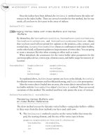
Look (Forward) vector is obtained.) For the billboarding effect to work, the vertices
that create the textured face must be centered at the origin. Also, the object must be
centered in the image (see Figure 9-5).
CHAPTER 9
Texturing Your Game World
FIGURE 9-5
Objects within billboarded images must be centered on the X axis.
MICROSOFT XNA GAME STUDIO CREATOR’S GUIDE
140
Billboarding Example
This example begins with the solution from the transparency code in Part C of the
previous example. In Chapter 8, logic is used to rotate the object drawn about the Y
axis so that it points in the direction it travels. This same logic can be used to rotate
the tree about the Y axis so it always faces the viewer and will consequently always
look like a bushy tree at any camera angle. In Figure 9-3 you can see the tree face the
viewer regardless of the angle.
As in Chapter 8, the Atan2() function uses the changes in direction on X and Z as
parameters to calculate the angle of direction about the Y axis. However, for this
case, the camera’s Look vector is used to obtain the direction parameters. The Look
direction equals the View position minus the camera position. (Refer to Chapter 17
for more detail on the Look vector that stores the direction of the camera.)
Adding GetViewerAngle() to the game class provides a method that returns
the rotation angle about the Y axis. This angle matches the camera’s angle about the
Y axis. When the tree is rotated about the Y axis (by the amount returned from this
function), the tree will always face the viewer:
float GetViewerAngle()
{ // use camera look direction to get
// rotation angle about Y
float x = cam.view.X - cam.position.X;
float z = cam.view.Z - cam.position.Z;
return (float)Math.Atan2(x, z) + MathHelper.Pi;}
Inside DrawSurfaces(), in the case that handles the TREE identifier, you need
to add code to reset the Y rotation matrix based on the camera’s rotation about the Y
axis. This creates the billboard effect that makes the tree look real from a distance.
rotationY = Matrix.CreateRotationY(GetViewerAngle());
After you have made these changes, try running the program. The tree will appear
like a nice, full, bushy tree, regardless of the angle of the camera.
Texture Coloring Example
This example shows how to colorize your image textures. This example begins with
the solution from the previous example. You can also find this solution in the Solu-
tions folder in this book’s download. The discussion in this section shows how to
change the color of the texture for the back wall.
141
In the InitializeSurface() method, replace the line that sets the color for
the vertices from white to red:
Color color = Color.Red;
When you run your code after this change you will see that the textures drawn
with these modified vertices are rendered with a red tint.
By now, you should see that applying images makes the 3D world a lot more inter-
esting. Simple effects such as tiling, color, transparency, and billboarding can be ap-
plied with little effort.
C
HAPTER 9 REVIEW EXERCISES
Here are some exercises that focus on some of the key points for applying texture
effects:
1. Try the step-by-step examples presented in this chapter, if you have not
already done so.
2. State four differences between a shader that enables texturing and a shader
that only handles position and color.
3. List the objects that need to be added to the C# code to add in a second
shader that allows textures.
4. List the states that must be set to enable transparency.
5. Create a building and apply textures to the sides. Add a billboarded tree,
cactus, or flower that you create with transparency.
CHAPTER 9
Texturing Your Game World
This page intentionally left blank
CHAPTER
CHAPTER 10
Adding Skies
Adding Skies
and Horizons
and Horizons
to Your
to Your
Levels
Levels
144
THIS
chapter explains how to create a realistic sky effect with an infi-
nite horizon. By the time you finish working through this chap-
ter, the sunny blue atmosphere you create will look so tranquil and inviting that you
may want to crawl inside your 3D world and never leave.
T
HE SKYBOX
The structure that houses the images that create the sky and horizon is often referred
to as a skybox. When the skybox is built properly, it is seamless—you can’t tell where
it begins or ends. Figure 10-1 shows three different camera views of a 3D world from
within a skybox.
A skybox is built using six images to create the sides, sky, and ground for the hori-
zon. Each individual image is shown in Figure 10-2.
To create the effect of an infinite horizon, each of the four wall images and the sky
image translate with the camera, but the ground image remains stationary. The result
allows you to see the ground move underneath you as you travel, but you will never
reach the horizon.
The walls of your virtual world are draped so that they fall slightly below the
ground. This means that the bottom edges of the walls are hidden. Figure 10-3 illus-
trates the stationary ground and its position relative to the moving ceiling and
draped walls.
FIGURE 10-1
Viewing a skybox from different camera angles
145
Terragen Photorealistic Scenery Rendering Software
Excellent tools are available to create your skybox. Terragen
( from Planetside is a popular utility for generating
photorealistic scenery that you can use for spectacular landscapes, seascapes, and
skyscapes. The beauty of Terragen is also evident in its ease of use.
Thanks to Planetside, a link to the download for the noncommercial edition of
Terragen is included on the website for this book. The noncommercial version is free
for personal use. However, the registered commercial version offers access to sup-
port, the ability to render larger and higher-quality images, enhanced anti-aliasing
modes, and, of course, permission to deploy works created using Terragen for com-
mercial purposes. Refer to the Planetside website for licensing and update details.
CHAPTER 10
Adding Skies and Horizons to Your Levels
FIGURE 10-2
Six images used to make the skybox
FIGURE 10-3
Moving ceiling and draped walls with a stationary ground of skybox
Using Terragen to Create a Skybox
This demonstration explains the steps needed to create the six images used to make a
skybox.
When you open Terragen, the application launches the main window, presented
in Figure 10-4.
Setting Up the Terragen Project
When you are setting up a Terragen project, you should assign several properties be-
fore you create your images. This ensures consistency among the images you gener-
ate. The properties you need to set govern image size, magnification, quality, camera
position, and target position for generating land and sky scenery.
Sizing the Image To ensure consistent sizing for all images, you should give each
image in the skybox the same pixel width and height dimensions. To set the dimen-
sions, click the Image Size button to open the Render Settings dialog. On the Image
tab of the Render Settings dialog, you can enter numeric values for Width and Height
(both values are in pixels). For this demonstration, a size of 512 pixels by 512 pixels
is recommended.
MICROSOFT XNA GAME STUDIO CREATOR’S GUIDE
146
FIGURE 10-4
Terragen main window
147
A higher pixel count enables better-quality images, but higher pixel counts also re-
duce the memory available. This may lower the frame rate in your game because it
takes more processing power for the game engine to render the sky.
Setting the Zoom Magnification The camera’s zoom magnification must be set to 1
to ensure that the images are scaled properly when creating each snapshot for the
sides of the skybox. This setting can be adjusted using the Zoom Magnification slider
in the Camera Settings dialog, which you can access by clicking the Camera Settings
button in Terragen’s main window.
Setting the Image Quality You can specify additional filter settings to improve im-
age quality. For example, you can adjust values for atmosphere and cloud effects. To
do this from Terragen’s main window, click the Render Settings button. This opens
the Render Settings dialog. In this dialog, you can increase the Accuracy settings for
Atmosphere and Cloud Shading from the Quality tab. If you want to avoid
pixelation, it is strongly recommended that you select high levels of accuracy for At-
mosphere and Cloud Shading.
Setting the Detail Level If you want to ensure that your images are rendered with
minimal pixelation, you must set the Detail slider on Terragen’s main window to full
strength. Leaving the slider at a lower setting reduces the image-generation time, but
the pixelation is noticeably worse; this problem will be magnified when the image is
used for the skybox. Figure 10-4 shows Terragen’s main window with the Detail set-
ting at full strength.
Setting the Camera and Target Positions While working in the main window of your
Terragen project, it is possible to specify the position of the camera and the target posi-
tion viewed by the camera. You can experiment with these settings if you choose. The
settings used while creating the skybox images for this chapter are summarized in Ta-
ble 10-1. If you are new to Terragen, we recommend that you try these settings; they
will allow you to create a skybox similar to the one shown in Figure 10-1. These set-
tings are also visible in Terragen’s Rendering Control dialog (see Figure 10-4).
CHAPTER 10
Adding Skies and Horizons to Your Levels
Setting X Y Z
Camera Position 4200.m 4400.m 65.4m
Fixed Height Above Surface Yes 65.4m
Target Position 4200.m 7935.7m 65.4m
Fixed Height Above Surface Yes 0.0m
Camera Position and Target Position Settings
TABLE 10-1
Checking the Land and Sky Options Select the Land and Sky options in Terragen’s
main window to generate ground and cloudscapes for your scenery.
Creating Each Image: Assigning Head, Pitch,
and Bank Properties
If you followed the instructions in the previous section, your global settings for the
Terragen project will be set. Each individual image, in the skybox, will have specific
settings that generate a unique picture that fits with the other images that make the
skybox.
Setting Up Each Snapshot When all of your images are assembled in the box, the
edges of each picture must match up with the edges of the neighboring picture. To
achieve a perfect set of matching images, you must give the camera a carefully
planned and unique angle for each snapshot. Terragen refers to these camera direc-
tion settings as
Head
,
Pitch
, and
Bank
attributes. These attributes set direction on
the X, Y, and Z planes. Later in this chapter, a code example shows you how to load
and display Terragen images in your game project. For the code example to work
properly, you must generate the named image files and their corresponding
Head
,
Pitch
, and
Bank
properties with the settings summarized in Table 10-2.
Rendering and Saving Each Image To create each image from Terragen’s main win-
dow, enter the Head, Pitch, and Bank settings and then click Render Image. A bitmap
appears in the resulting Image dialog. You can then save the image by clicking the
Save button in the top-left corner of the Image dialog.
After completing the steps for creating each image, you should have a directory
that contains your brand new front.bmp, back.bmp, left.bmp, right.bmp, sky.bmp,
MICROSOFT XNA GAME STUDIO CREATOR’S GUIDE
148
Image Name Camera Orientation
Head Pitch Bank
front.bmp 0 0 0
left.bmp 90 0 0
back.bmp 180 0 0
right.bmp –90 0 0
sky.bmp –90 90 0
ground2.bmp –90 –90 0
Camera Direction Settings for Each Image of the Skybox
TABLE 10-2
149
and ground2.bmp images. You can now load these into your game project and create
the skybox.
Skybox Code Example This example takes your new images and renders them to
create a seamless sky with an endless horizon. For this example, you can use either
the MGHWinBaseCode project or the MGH360BaseCode project from the book’s
download.
Once the base project is ready, you will need to load the images you created with
Terragen. To add the images to your project, copy them into the Images directory un-
der the Content node that already exists in your project. Next, click the Show All
Files button in the Solution Explorer, select the new images that appear under the Im-
ages folder, and then right-click and choose Include in Project. When you are done,
you will see all of your skybox images referenced under the Images folder in the Solu-
tion Explorer.
Now that your images are referenced in your game project; the next step is to de-
clare variables for storing them. These must be declared at the top of your game class.
Texture2D frontTexture, backTexture, groundTexture,
leftTexture, rightTexture, skyTexture;
To assign these images at startup, place the image-loading code inside the
LoadContent() method:
frontTexture = Content.Load<Texture2D>("Images\\front");
backTexture = Content.Load<Texture2D>("Images\\back");
leftTexture = Content.Load<Texture2D>("Images\\left");
rightTexture = Content.Load<Texture2D>("Images\\right");
groundTexture = Content.Load<Texture2D>("Images\\ground2");
skyTexture = Content.Load<Texture2D>("Images\\sky");
Textured ground already exists in the base project. It is currently tiled ten times,
but the skybox ground texture is not designed for tiling. Inside
InitializeGround(), all uv.X or uv.Y values set to 10.0f must be replaced with
code that sets them to 1.0f to ensure that the texture is mapped to the ground surface
on a one-to-one basis. Also, to replace the existing image with the ground2.bmp im-
age from Terragen, in step 4 of DrawGround() (marked by the comments in the
code), replace the instruction that sets the texture using
grassTexture
with an in-
struction to use the
groundTexture
image:
textureEffectImage.SetValue(groundTexture);
CHAPTER 10
Adding Skies and Horizons to Your Levels
MICROSOFT XNA GAME STUDIO CREATOR’S GUIDE
150
If you try the program now, you will see the same 3D world, but this time the
ground will be covered with the texture you created in Terragen.
Once the ground is properly rendered with the texture, the surrounding walls and
ceiling of the skybox can be added. By design, the edges of the skybox surround the
outer perimeter of the world, so the skybox walls must be bigger than the world
walls. A class-level definition for the skybox panel size must be proportionately
larger than the world boundary size:
private const float EDGE = BOUNDARY * 2.0f;
A set of vertices is required to store the vertex position, texture, and color informa-
tion for a rectangle that can be used to make each surface of the skybox. This same
surface can be redrawn using a different set of rotations and translations to create
each panel of the skybox as long as the appropriate texture is used each time it is
drawn. Because only one rectangular surface is required to draw all sides of the
skybox, the vertex array only needs to be declared with room for four sets of coordi-
nates:
private VertexPositionColorTexture[] skyVertices = new
VertexPositionColorTexture[4];
The InitializeSkybox() method contains the necessary code to set up the
vertices that can be used to render a skybox panel. As mentioned earlier, the same
four vertices are used to draw each panel. Remember that the length of the panels
must be greater than the length of the world size. The module-level definition, EDGE,
is used to set the X and Z values of each vertex to ensure that the panels are large
enough to surround the perimeter of the 3D world.
Each time these coordinates are used to draw a panel, they must be rotated and
translated into position. Notice how the rectangle’s X, Y, and Z coordinates are cen-
tered about the origin where X=0, Y=0, and Z=0. This enables easier rendering.
Note that the UV coordinates that enable texture mapping are between 0.003f and
0.997f. This shortened range from the usual 0.0f to 1.0f setting removes the white
seam that outlines each bitmap. The UV offset of 0.003f preserves the illusion of the
skybox.
private void InitializeSkybox(){
Vector3 pos = Vector3.Zero;
Vector2 uv = Vector2.Zero;
Color color = Color.White;
const float MAX=0.997f; // offset to remove white seam at image edge
const float MIN=0.003f; // offset to remove white seam at image edge
151
// set position, image, and color data for each vertex in rectangle
pos.X=+EDGE; pos.Y=-EDGE; uv.X=MIN; uv.Y=MAX; //Bottom R
skyVertices[0]=new VertexPositionColorTexture(pos, color, uv);
pos.X=+EDGE; pos.Y=+EDGE; uv.X=MIN; uv.Y=MIN; //Top R
skyVertices[1]=new VertexPositionColorTexture(pos, color, uv);
pos.X=-EDGE; pos.Y=-EDGE; uv.X=MAX; uv.Y=MAX; //Bottom L
skyVertices[2]=new VertexPositionColorTexture(pos, color, uv);
pos.X=-EDGE; pos.Y=+EDGE; uv.X=MAX; uv.Y=MIN; //Top L
skyVertices[3]=new VertexPositionColorTexture(pos, color, uv);
}
To be sure the skybox is initialized only once, add the call statement to the Ini-
tialize() method:
InitializeSkybox();
To draw each panel of the skybox, you must add the DrawSkybox() method to
the game class. This method is designed to iterate through all five moving panels of
the skybox, transform each panel into place, and render it with the correct texture.
Step 1 declares a set of matrices and initializes each matrix with a default value. In
step 2, the transformations are assigned so that the sides and the ceiling of the skybox
are drawn where they belong. Also in step 2, the corresponding texture for each panel
is set. In step 3, the I.S.R.O.T. sequence is used to calculate the cumulative transfor-
mation. Of course, this order of transformations is crucial and cannot change. The
last extra translation, camTranslation, translates the skybox panels so that they
move with the camera and give the illusion of an unreachable horizon.
private void DrawSkybox(){
const float DROP = -1.2f;
// 1: declare matrices and set defaults
Matrix world;
Matrix rotationY = Matrix.CreateRotationY(0.0f);
Matrix rotationX = Matrix.CreateRotationX(0.0f);
Matrix translation = Matrix.CreateTranslation(0.0f, 0.0f, 0.0f);
Matrix camTranslation // move skybox with camera
= Matrix.CreateTranslation(cam.position.X, 0.0f, cam.position.Z);
// 2: set transformations and also texture for each wall
CHAPTER 10
Adding Skies and Horizons to Your Levels
for (int i = 0; i < 5; i++){
switch (i){
case 0: // BACK
translation = Matrix.CreateTranslation(0.0f, DROP, EDGE);
textureEffectImage.SetValue(backTexture); break;
case 1: // RIGHT
translation = Matrix.CreateTranslation(-EDGE, DROP, 0.0f);
rotationY = Matrix.CreateRotationY(-(float)Math.PI/2.0f);
textureEffectImage.SetValue(rightTexture); break;
case 2: // FRONT
translation = Matrix.CreateTranslation(0.0f, DROP, -EDGE);
rotationY = Matrix.CreateRotationY((float)Math.PI);
textureEffectImage.SetValue(frontTexture); break;
case 3: // LEFT
translation = Matrix.CreateTranslation(EDGE, DROP, 0.0f);
rotationY = Matrix.CreateRotationY((float)Math.PI/2.0f);
textureEffectImage.SetValue(leftTexture); break;
case 4: // SKY
translation = Matrix.CreateTranslation(0.0f,EDGE+DROP, 0.0f);
rotationX = Matrix.CreateRotationX(-(float)Math.PI/2.0f);
rotationY =
Matrix.CreateRotationY(3.0f*MathHelper.Pi/2.0f);
textureEffectImage.SetValue(skyTexture); break;
}
// 3: build cumulative world matrix using I.S.R.O.T. sequence
world = rotationX * rotationY * translation * camTranslation;
// 4: set shader variables
textureEffectWVP.SetValue(world * cam.viewMatrix
* cam.projectionMatrix);
// 5: draw object - primitive type, vertices, # primitives
TextureShader(PrimitiveType.TriangleStrip, skyVertices, 2);
}
}
To trigger the code to draw the skybox from the Draw() method, add this instruc-
tion:
DrawSkybox();
MICROSOFT XNA GAME STUDIO CREATOR’S GUIDE
152