Microsoft XNA Game Studio Creator’s Guide- P5 ppsx
Bạn đang xem bản rút gọn của tài liệu. Xem và tải ngay bản đầy đủ của tài liệu tại đây (319.89 KB, 30 trang )
MICROSOFT XNA GAME STUDIO CREATOR’S GUIDE
98
The vertices for the earth and moon are set when the program begins, so
InitializeTriangle() is called from the Initialize() method:
InitializeTriangle();
When animating the triangle, a time-scaled increment is made to the triangle’s ro-
tation during each Update(). This rotation value is modded by 2π to clamp the
value between 0 and 2π.
earthRotation += gameTime.ElapsedGameTime.Milliseconds/1000.0f;
earthRotation = earthRotation%(2.0f * MathHelper.Pi);
moonRotation += (float)TargetElapsedTime.Milliseconds/750.0f;
moonRotation = moonRotation %(2.0f * MathHelper.Pi);
Here are the five recommended steps for drawing the revolving Earth object:
1. Declare the matrices.
2. Initialize the matrices. The identity matrix is initialized as a default matrix
in the event of no transformations. (Try leaving it out of the transformation,
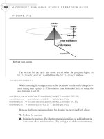
FIGURE 7-2
Earth and moon example
99
and notice you still get the same result.) A matrix that generates the earth’s
revolution on the Y axis is computed based on a constantly changing angle
(in radians). Every frame, the angle is incremented with a value based on
the time lapse between frames. This time-scaled increment to the rotation
angle ensures that the animation appears smoothly while maintaining a
constant rate of change. Scaling the increment based on time is necessary
because durations between frames can vary depending on other tasks being
performed by the operating system. Finally, a translation is created to move
the earth 0.5 units upward on the Y axis and 8.0 units inward on the Z axis.
3. The World matrix is built by multiplying each of the matrices in the
transformation using the I.S.R.O.T. sequence.
4. The World matrix used to transform the earth is passed to the shader as
part of the World*View*Projection matrix.
5. The triangle is rendered by drawing vertices with a triangle strip.
Adding DrawEarth() to the game class provides the code needed for transform-
ing and drawing the Earth:
private void DrawEarth(){
// 1: declare matrices
Matrix world, translation, rotationY;
// 2: initialize matrices
rotationY = Matrix.CreateRotationY(earthRotation);
translation = Matrix.CreateTranslation(0.0f, 0.5f, -8.0f);
// 3: build cumulative World matrix using I.S.R.O.T. sequence
// identity, scale, rotate, orbit(translate & rotate), translate
world = rotationY * translation;
// 4: set shader parameters
positionColorEffectWVP.SetValue(world * cam.viewMatrix
* cam.projectionMatrix);
// 5: draw object - select primitive type, vertices, # primitives
PositionColorShader(PrimitiveType.TriangleStrip, triangleVertex, 1);
}
CHAPTER 7
Animation Introduction
MICROSOFT XNA GAME STUDIO CREATOR’S GUIDE
100
Next, the DrawMoon() method implements the same five-step drawing routine to
transform and render the same vertices as a Moon object. The moon has its own revo-
lution about the Y axis, and it also orbits around the earth. In addition, the moon is
scaled to one-fifth the size of the earth.
The DrawMoon() method performs all of the same transformations as the
DrawEarth() method. Plus, DrawMoon() implements scaling and an orbit. All of
the matrices declared in the DrawEarth() method are declared in DrawMoon() to
perform the same transformations. Also, additional matrices are declared and set in
this method to handle the scaling and orbit. The scale is set to draw the object at
one-fifth the size of the earth by assigning the scale matrix the following value:
Matrix.CreateScale(0.2f, 0.2f, 0.2f);
Remember that the orbit is a two-step process that involves a translation followed
by a rotation. When the World matrix is built, the crucial I.S.R.O.T. sequence is used
to ensure that the matrices are multiplied in the proper order:
world = scale * rotationY * orbitTranslation * orbitRotationY
* translation;
Since the same vertices are used for drawing the Moon and the Earth, steps 4 and
5 of DrawMoon() are identical to those in DrawEarth().
private void DrawMoon(){
// 1: declare matrices
Matrix world, scale, rotationY, translation,
orbitTranslation, orbitRotationY;
// 2: initialize matrices
scale = Matrix.CreateScale(0.2f, 0.2f, 0.2f);
rotationY = Matrix.CreateRotationY(moonRotation);
translation = Matrix.CreateTranslation(0.0f, 0.8f,-8.0f);
orbitTranslation = Matrix.CreateTranslation(0.0f, 0.0f,-1.0f);
orbitRotationY = Matrix.CreateRotationY(moonRotation);
// 3: build cumulative World matrix using I.S.R.O.T. sequence
// identity, scale, rotate, orbit(translate & rotate), translate
world = scale * rotationY * orbitTranslation
* orbitRotationY * translation;
101
CHAPTER 7
Animation Introduction
// 4: set the shader parameters
positionColorEffectWVP.SetValue(world * cam.viewMatrix
* cam.projectionMatrix);
// 5: draw object - select primitive type, vertices, # of primitives
PositionColorShader(PrimitiveType.TriangleStrip, triangleVertex, 1);
}
Both the DrawEarth() and DrawMoon() methods are called from the Draw()
method in the game class:
DrawEarth();
DrawMoon();
When you compile and run this code, it will show the earth as a revolving triangle
being orbited by a revolving moon (refer to Figure 7-2).
Spend the time you need to ensure that you understand transformations. It is not an
overly complex topic, but it can be challenging for beginner graphics programmers
who do not give transformations the learning time the topic deserves. You will enjoy
the rest of the book more when you have mastered this introduction to animation.
Be fearless when experimenting with your transformations. When you test and
run your projects, you will probably know right away if your transformations are
working properly. Of course, use the documentation presented in this section as a
guide to understanding the topic. The real learning will happen when you try to cre-
ate your own transformations.
C
HAPTER 7 REVIEW EXERCISES
To get the most from this chapter, try out these chapter review exercises.
1. Implement the step-by-step example presented in this chapter, if you have
not already done so.
2. Using primitives, create a stationary airplane with a rotating propeller that
is made from triangles, as in the following illustration. When initializing
the vertices that store the propeller, be sure to center the X, Y, and Z
coordinates around the origin. Failure to center the X, Y, and Z coordinates
of your surface about the origin will offset your rotations and will lead to
strange results when unbalanced objects are transformed (see Figure 7-3).
3. When you finish Exercise 2, transform your propeller so it serves as a rotor
for a helicopter. Using the same set of vertices, write another procedure to
transform and render the same rectangle used for the main rotor as a back
rotor, as shown here in Figure 7-4.
MICROSOFT XNA GAME STUDIO CREATOR’S GUIDE
102
FIGURE 7-3
Primitive airplane with rotating propeller
FIGURE 7-4
Helicopter with top and back rotors using the same vertices
CHAPTER
CHAPTER
8
8
Character
Character
Movement
Movement
104
AFTER
reading and applying the material covered in Chapter 7,
you should be comfortable performing simple animations
with translations and rotations. For most gamers, it is not enough just to make a bird
flap its wings or make the propeller of an airplane spin; anybody with half an ounce
of curiosity wants to see these objects actually fly. This chapter introduces a simple
animation method that allows moving objects to travel independently within your
3D world.
Additional methods for enabling the movement of objects are covered in
Chapter 21.
Regardless of the method used to move objects and characters, basic movement is
generated by updating the X, Y, and Z position coordinates, as well as the rotation
angles of the moving object rendered at every frame.
D
IRECTION
When you animate vehicles that fly, drive, sail, or glide, you most likely expect them
to point in the direction they are traveling. Calculating the angle of direction can be
done using several methods. Without this calculation, your vehicles could look as if
they are flying backward or even sideways. Trigonometry offers a simple intuitive
approach to calculate the angle of direction—this method will be used often through-
out this book. However, computing direction can also be done with vectors. Using
vectors to calculate direction is actually a more powerful method for implementing
rotations of direction because they offer a simpler means to implement complex
transformations for directions in all planes.
Calculating Direction Using Trigonometry
The trigonometry applied in this chapter is actually quite simple and only involves
using the arctangent function. The arctangent function enables calculations of direc-
tion about the Y axis when the X and Z coordinates of the object are known.
When the Right Hand Rule is used, all positive rotations are counterclockwise. To
calculate an object’s angle about the Y axis, draw a line from the object’s position to
the preceding axis in the rotation to create a right-angle triangle. The tangent of the
angle between the hypotenuse and the axis can be calculated with the following equa-
tion:
tan φ side length / adjacent side length (where φ is the angle)
105
This equation can be rearranged to isolate the angle:
φ = tan
–1
(opposite / adjacent)
φ = atan (opposite / adjacent)
Figure 8-1 shows the angle about the Y axis in relation to the hypotenuse, oppo-
site, and adjacent sides of the right-angle triangle.
Calculating Direction Using Speed
When Y is constant, the change in X and Z, during each frame, measures speed. On
a three-dimensional graph, the X and Z speed combination will always fall in one
of four quadrants, depending on whether each of the X and Z speeds is positive or
negative.
Calculating Direction Using the Math.Atan()
Function
To calculate the angle of direction about the Y axis, create an imaginary right-angle
triangle by drawing a line from the X, Z coordinate to the preceding X or Z axis. This
line must be perpendicular to the X or Z axis. You can use XNA’s Math.Atan()
function to compute the angle of rotation about the Y axis using the corresponding X
and Z values as opposite and adjacent parameters:
double radians = Math.Atan( (double)opposite/(double)adjacent );
CHAPTER 8
Character Movement
FIGURE 8-1
Hypotenuse, opposite, and adjacent sides of a right-angle triangle
The Math.Atan() function then returns the angle of rotation about Y for the im-
mediate quadrant. An offset that equals the total rotation for the preceding quad-
rants is added to this angle to give the total rotation in radians. Figure 8-2 illustrates
the relationship between the X and Z speeds for each quadrant and their offsets.
When the Math.Atan() function is used, each quadrant uses a slightly different
equation to generate the rotation about the Y axis. These individual quadrant equa-
tions are summarized in Table 8-1.
Understanding this basic trigonometry can help you develop algorithms to gener-
ate your own direction angles.
MICROSOFT XNA GAME STUDIO CREATOR’S GUIDE
106
FIGURE 8-2
Calculating angle of direction about the Y axis using speed quadrants
Quadrant Offset Equation
10
Math.Atan (-z/x)
2 /2
Math.Atan (-x/-z) + /2
3
Math.Atan (z/–x) +
43/2
Math.Atan (x/z) + 3 /2
Quadrant Equations to Calculate the Angle of Direction About the Y Axis
TABLE 8-1
107
CHAPTER 8
Character Movement
Calculating Direction Using the Math.Atan2()
Function
Thankfully, there is an easier way to employ trigonometry to calculate the angle of
direction about the Y axis. The Math.Atan2() function eliminates the need to fac-
tor quadrant differences into the calculations. To compute the angle of rotation
about the Y axis with the Math.Atan2() function, the calculation becomes this:
double radians = Math.Atan2((double) X / (double) Z)
This equation can be used to calculate the angle of direction about the Y axis for
all quadrants.
Both the Math.Atan() and Math.Atan2() functions will be demonstrated in
the example presented in this chapter.
Calculating Direction Using Vectors
Calculating direction using vectors is the more powerful method. The math behind
implementing vectors of direction is explained in more detail later, in Chapters 15,
16, and 17, so you may choose to read these chapters first for a better understanding
of how the vectors work. The vector logic for calculating direction is being presented
ahead of these chapters to ensure you have a better way to move your vehicles, ves-
sels, and aircraft through your 3D world.
The vectors that describe the orientation of a moving object can be summarized
using the Look, Up, and Right vectors. These vectors describe the moving object’s
direction and uprightness (see Figure 8-3).
The Look vector, also known as the Forward vector, is calculated from the differ-
ence in the view position and the position of the object. When you are animating ob-
jects, the Look vector could also be the same as the object’s speed vector. The Up
vector describes the upright direction. For most objects that are animated in this
book, the starting upright direction is 0, 1, 0. When we stand on our own two feet, we
have an Up vector of 0, 1, 0. The Right vector describes the perpendicular from the
surface created by the Up and Look vectors. The Right vector can be used for a
strafe in addition to assisting with the computation of angles of direction.
If the Up vector is known, the Right vector can be calculated using the cross prod-
uct of the Look and Up vectors. The Right vector equals the cross product of the Up
and Look vectors.
MICROSOFT XNA GAME STUDIO CREATOR’S GUIDE
108
When these vectors are normalized, or scaled so their lengths range between -1
and 1, they can be used in a matrix that calculates the direction. The cells of the ma-
trix are defined with the data from the three direction vectors:
M.M11 = R.X; M.M12 = R.Y; M.M13 = R.Z; M.M14 = 0.0f; //Right
M.M21 = U.X; M.M22 = U.Y; M.M23 = U.Z; M.M24 = 0.0f; //Up
M.M31 = L.X; M.M32 = L.Y; M.M33 = L.Z; M.M34 = 0.0f; //Look
M.M41 = 0.0f; M.M42 = 0.0f; M.M43 = 0.0f; M.M44 = 1.0f;
XNA’s Matrix struct actually exposes each of these three direction vectors by
name. If we create a transformation matrix called direction, we can reference
these vectors with the Matrix struct’s Right, Up, and Forward properties:
Vector3 right = direction.Right;
Vector3 up = direction.Up;
Vector3 look = direction.Forward;
An example showing how to implement this structure is presented later in the
chapter.
Scaling Animations with Time Lapse Between Frames
When animating objects, it is essential to ensure that your animations run at the same
speed regardless of the processing power of the system that runs them. If you are a
FIGURE 8-3
Direction vectors
109
CHAPTER 8
Character Movement
starving student, you might only be able to afford a slow PC—maybe with an older
graphics card—but the computers in the labs at your college or university might be
faster, or vice versa. If you develop your games on a slow PC, and you don’t regulate
the timing of your animations, they will look as if they are playing in fast forward
when you run them on a faster PC. The reverse is true if you develop your games on a
super-charged PC and then run them on a slower machine. Also, when you port your
games over to the Xbox 360, you are almost certain to experience a difference in pro-
cessing power compared to your development PC. To compound this issue, every
frame of your game will exert different demands on the processor, and you might be
running other programs in the background that are stealing valuable processor cy-
cles. With all of these varying system and performance factors to consider, a mecha-
nism to control the speed of your animations is a must-have item.
The trick to controlling animation speed is simple. The equation used to control
the translation speed looks like this:
Vector3 Position += Increment.XYZ * TimeBetweenFrames / ConstantScale;
Controlling rotation speed is similar:
float radians += Increment * TimeBetweenFrames / ConstantScale;
These equations offer a self-adjusting mechanism to account for varying frame
rates. For example, a faster machine will produce more frames, but the animation
won’t run faster, because the time scale will reduce the increment for each frame. In
the end, you will have more frames and a smoother animation, but the animation
speed will be the same as an animation that runs on a slower machine. If you do not
factor in the time difference between frames, your animations will run at uncontrol-
lable speeds.
Character Movement Example
In this example, you will animate a single-prop aircraft so that it flies within the
boundaries of your virtual world. Of course, you will also ensure that the plane is
pointing in the direction it’s supposed to fly; first with methods that use trigonometry
and then with methods that use direction vectors. This example demonstrates how to
use animations that involve translations and rotations, how to animate an object at a
constant speed, and how to calculate the angle of direction using a constant speed.
To keep this example simple, the airplane is built with nothing more than a trian-
gle for the body and a spinning rectangle for the propeller (see Figure 8-4).
MICROSOFT XNA GAME STUDIO CREATOR’S GUIDE
110
If you want, you can easily swap these primitive objects with 3D models; the se-
quence of instructions to create the transformation for the animation would remain
identical.
This example begins with either the files in the MGHWinBaseCode project or the
MGH360BaseCode project from the BaseCode folder on this book’s website.
A Stationary Airplane with a Spinning Propeller
This first part of the demonstration explains how to create an airplane using a sta-
tionary triangle and a rotating rectangle that is perpendicular to the front tip of the
triangle. Two separate objects for storing vertices are needed: the body of the air-
plane and the propeller. Their declarations are required in the module-level area of
the game class:
VertexPositionColor[] airplaneVertices = new VertexPositionColor[3];
VertexPositionColor[] propellerVertices = new VertexPositionColor[4];
Code to initialize each vertex—in both the airplane and the propeller—sets the po-
sition and color values for each coordinate. Note that the vertices for each object are
centered around the origin. As explained previously, any space from the origin to the
center of an object is actually a translation that will literally send your object into an
FIGURE 8-4
Airplane animation
111
orbit when you rotate it. If you have already felt the mental pain from trying to debug
this problem before realizing your vertices are not centered—welcome to the club!
The methods InitializeAirplaneBody() and InitializePropeller()
are added to the game class to initialize each array of vertices:
private void InitializeAirplaneBody(){
Vector3 position;
Color color = Color.Orange;
position = new Vector3(0.0f,-0.25f, 0.5f); // lower front
airplaneVertices[0] = new VertexPositionColor(position, color);
position = new Vector3(0.0f, 0.25f,-0.5f); // top back
airplaneVertices[1] = new VertexPositionColor(position, color);
position = new Vector3(0.0f,-0.25f,-0.5f); // lower back
airplaneVertices[2] = new VertexPositionColor(position, color);
}
private void InitializePropeller(){
Vector3 position;
Color color = Color.LightBlue;
position = new Vector3(-0.5f, 0.05f, 0.0f);// top left
propellerVertices[0] = new VertexPositionColor(position, color);
position = new Vector3(-0.5f,-0.05f, 0.0f);// lower left
propellerVertices[1] = new VertexPositionColor(position, color);
position = new Vector3(0.5f, 0.05f, 0.0f);// top right
propellerVertices[2] = new VertexPositionColor(position, color);
position = new Vector3(0.5f, -0.05f, 0.0f);// lower right
propellerVertices[3] = new VertexPositionColor(position, color);
}
To initialize the propeller and the airplane body, when the program begins, call
InitializeAirplaneBody() and InitializePropeller() from Ini-
tialize():
InitializeAirplaneBody();
InitializePropeller();
In the beginning of this demonstration, the airplane is drawn as a stationary ob-
ject. A translation matrix generated by the instruction:
translation = Matrix.CreateTranslation(0.0f, 0.75f, -8.0f);
CHAPTER 8
Character Movement
MICROSOFT XNA GAME STUDIO CREATOR’S GUIDE
112
moves the plane in a one-time translation 0.75 units up the Y axis and -8.0 units in-
ward along the Z axis. A slight rotation is generated with this instruction:
rotationY = Matrix.CreateRotationY(MathHelper.Pi/8.0f);
This makes it easier to view the airplane from the camera’s starting position.
When the rotation and translation are combined, the I.S.R.O.T. (Identity, Scale, Re-
volve, Orbit, Translate) sequence is used to build the cumulative transformation:
world = rotationY * translation;
DrawAirplaneBody() declares and initializes the transformation matrices in
the first two steps. Then, the cumulative World matrix is built in the third step. In the
fourth step, the cumulative transformation stored in the World matrix is sent to the
shader. Finally, in the fifth step, the triangle is drawn from the transformed vertices.
DrawAirplaneBody() is added to the game class to transform and render the ver-
tices for the triangle.
private void DrawAirplaneBody(){
// 1: declare matrices
Matrix world, translation, rotationY;
// 2: initialize matrices
translation = Matrix.CreateTranslation(0.0f, 0.75f, -8.0f);
rotationY = Matrix.CreateRotationY(MathHelper.Pi/8.0f);
// 3: build cumulative world matrix using I.S.R.O.T. sequence
// identity, scale, rotate, orbit(translate & rotate), translate
world = rotationY * translation;
// 4: set shader parameters
positionColorEffectWVP.SetValue(world * cam.viewMatrix
* cam.projectionMatrix);
// 5: draw object - primitive type, vertices, total primitives
PositionColorShader(PrimitiveType.TriangleStrip,airplaneVertices,1);
}
Instructions for rendering the propeller are similar to steps taken to position and
draw the airplane. The main difference in DrawPropeller() is the inclusion of a
continuous rotation about the Z axis. Adding a variable to the game class to store ro-
113
tation on the Z axis will permit updates to this variable with each frame. This data
can be used to generate the continuous rotation.
float propellerSpin;
In this example, the propeller is assumed to be rotating counterclockwise, so the
calculation that generates the value for
propellerSpin
is always greater than or
equal to 0. If you need to reverse the rotation so it is negative, negating
propellerSpin
will generate clockwise rotation. The DrawPropeller()
method is added to the game class to transform and draw the vertices; this creates a
spinning rectangle. A time lapse between frames is obtained with the
TargetElapsedTime.Milliseconds attribute. Note that an orbit is required.
Non-orbit transformations are performed to move the propeller to the center of the
airplane body. Then, a translation across the body of the aircraft and a rotation in the
airplane body’s direction are required to move the propeller from the aircraft’s center
to the aircraft’s nose. This translation and rotation away from the center of the air-
craft is the orbit.
private void DrawPropeller(GameTime gameTime){
// 1: declare matrices
Matrix world, translation, orbitTranslate, orbitRotateY, rotationZ;
// 2: initialize matrices
// continous rotation - restrict it between 0 and 2pi
propellerSpin += gameTime.ElapsedGameTime.Milliseconds/50.0f;
propellerSpin = propellerSpin % (MathHelper.Pi * 2.0f);
rotationZ = Matrix.CreateRotationZ(propellerSpin);
orbitTranslate = Matrix.CreateTranslation(0.0f,-0.25f, 0.5f);
orbitRotateY = Matrix.CreateRotationY(MathHelper.Pi/8.0f);
translation = Matrix.CreateTranslation(0.0f, 0.75f, -8.0f);
// 3: build cumulative world matrix using I.S.R.O.T. sequence
// identity, scale, rotate, orbit(translate & rotate), translate
world = rotationZ * orbitTranslate * orbitRotateY * translation;
// 4: set shader parameters
positionColorEffectWVP.SetValue(world * cam.viewMatrix
* cam.projectionMatrix);
// 5: draw object - primitive type, vertices, # of primitives
PositionColorShader(PrimitiveType.TriangleStrip, propellerVertices, 2);
}
CHAPTER 8
Character Movement
Both DrawAirplaneBody() and DrawPropeller() are called from the
Draw() method where all drawing for your game application is triggered:
DrawAirplaneBody();
DrawPropeller(gameTime);
When you run this code, a stationary airplane body and a propeller that rotates on
the Z axis will appear (refer to Figure 8-4).
A Flying Airplane with a Spinning Propeller
For your airplane to move, it needs speed. And to calculate the speed, the current po-
sition must be tracked at every frame. Add the Vector3 variables,
speed
and
airplanePosition
, to the game class to enable speed and position tracking for
the airplane:
Vector3 speed;
Vector3 airplanePosition = new Vector3(0.0f, 0.75f, -8.0f);
When the speeds are initialized, they can be randomized. Using the
InitializeSpeed() method in your game class randomizes the airplane’s speed
when the program starts. This helps to ensure that the airplane’s route varies each
time the game is run:
void InitializeSpeed(){
Random randomNumber = new Random();
speed.X = -1.0f - randomNumber.Next(3);
speed.Z = -1.0f - randomNumber.Next(3);
}
The speed can be randomized at the beginning of the game by calling
InitializeSpeed() from the Initialize() method:
InitializeSpeed();
If updates to the airplane’s position are not monitored and adjusted, the airplane is
going to fly off into outer space. A check is needed to determine whether the X and Z
world boundaries are exceeded—in which case the corresponding speed on X or Z is
reversed. To allow the airplane to travel, the UpdateAirplanePosition()
method is added to the game class. This method updates the airplane’s position for
every frame. A time scale is obtained by dividing the total milliseconds between
frames by 1,000. Multiplying this scaled time value by the speed ensures that the ani-
mation will run at the same rate regardless of the system. For this example, the out-
MICROSOFT XNA GAME STUDIO CREATOR’S GUIDE
114
115
come ensures that the airplane will take the same time to travel from point A to point
B regardless of the computer’s processing power, the varying demands of your game
each frame, and the background processing on your system outside your game.
void UpdateAirplanePosition(GameTime gameTime){
// change corresponding speed if beyond world’s X and Z boundaries
if (airplanePosition.X > BOUNDARY || airplanePosition.X < -BOUNDARY)
speed.X *= -1.0f;
if (airplanePosition.Z > BOUNDARY || airplanePosition.Z < -BOUNDARY)
speed.Z *= -1.0f;
// increment position by speed * time scale between frames
float timeScale = gameTime.ElapsedGameTime.Milliseconds/1000.0f;
airplanePosition.X += speed.X * timeScale;
airplanePosition.Z += speed.Z * timeScale;
}
The UpdateAirplanePosition() method is called from the Update()
method to ensure that the airplane’s position variable is adjusted for each frame:
UpdateAirplanePosition(gameTime);
When this updated vector variable is applied—in a translation matrix against the
airplane’s body—it moves the airplane to the current position. Replacing the existing
CreateTranslation() instruction inside DrawAirplaneBody() and
DrawPropeller() will include the updated translation in the transformation:
translation = Matrix.CreateTranslation(airplanePosition);
When you run this program, the airplane will fly around the world and remain
within the boundaries. However, there is still a problem with this version of the ex-
ample. The airplane has no sense of direction and therefore appears to fly sideways.
Setting the Angle of Direction with Math.Atan()
This portion of the example adds the ability to point the airplane in the direction it is
traveling. The rotation implemented in this RotationAngle() method uses quad-
rants to calculate the angle of rotation about the Y axis:
float RotationAngle(){
float PI = MathHelper.Pi;
float rotationY = 0.0f;
// 1st quadrant
CHAPTER 8
Character Movement
if (speed.X >= 0.0f && speed.Z <= 0.0f)
rotationY = (float)Math.Atan(-speed.Z/+speed.X);
// 2nd quadrant
else if (speed.X <= 0.0f && speed.Z <= 0.0f)
rotationY = PI/2.0f + (float)Math.Atan(-speed.X/-speed.Z);
// 3rd quadrant
else if (speed.X <= 0.0f && speed.Z >= 0.0f)
rotationY = PI + (float)Math.Atan(+speed.Z/-speed.X);
// 4th quadrant
else if (speed.X >= 0.0f && speed.Z >= 0.0f)
rotationY = 3*PI/2.0f + (float)Math.Atan(+speed.X/+speed.Z);
return rotationY + PI / 2.0f;
}
Replacing the instruction for the creation of the Y rotation matrix—inside
DrawAirplaneBody()—creates a rotation about Y that matches the direction of
the aircraft:
rotationY = Matrix.CreateRotationY(RotationAngle());
This same replacement must be applied in the DrawPropeller() method to ro-
tate the propeller properly about the Y axis:
orbitRotateY = Matrix.CreateRotationY(RotationAngle());
When you compile and run this code, the airplane will fly through the world and
will point in the direction it is traveling.
Setting the Angle of Direction with Math.Atan2()
You could actually replace the existing RotationAngle() method with this sim-
pler version to get the same result. The longer version was shown first to demonstrate
how this simpler version actually works:
float RotationAngle(){
return (float)Math.Atan2((double)speed.X,(double)speed.Z);
}
This finished example shows an airplane that flies within the boundaries of the 3D
world and points in the direction it is traveling. The only difference with this last
change is the simplified instruction.
MICROSOFT XNA GAME STUDIO CREATOR’S GUIDE
116
117
Setting the Angle of Direction Using Vectors
As explained earlier, the direction vectors can be used to generate a rotation matrix.
To use the Look (speed), Up, and Right vectors to calculate the angle of direction,
add this method to your game class:
Matrix DirectionMatrix(){
// LOOK (FORWARD) vector stores forward direction
Vector3 L = speed;
L.Normalize();
// Default UP in this case is (0, 1, 0)
Vector3 U = new Vector3(0.0f, 1.0f, 0.0f);
U.Normalize();
// RIGHT is cross product (perpendicular) of UP and LOOK
Vector3 R = Vector3.Cross(U, L);
R.Normalize();
Matrix M=new Matrix();// compute direction rotation matrix M
M.M11= R.X; M.M12=R.Y; M.M13=R.Z; M.M14=0.0f; //RIGHT
M.M21= U.X; M.M22=U.Y; M.M23=U.Z; M.M24=0.0f; //UP
M.M31= L.X; M.M32=L.Y; M.M33=L.Z; M.M34=0.0f; //LOOK
M.M41= 0.0f; M.M42=0.0f; M.M43=0.0f; M.M44=1.0f;
return M;
}
Then, to replace the trigonometry reference in calculating the Y rotation angle, in
DrawAirplaneBody(), replace the instruction that creates the Y rotation matrix
with the following instruction:
rotationY = DirectionMatrix();
Inside DrawPropeller() you can change the rotation. As discussed, you per-
form the non-orbit tranformations to move the propeller to the center of the aircraft.
Then you perform the orbit to move the propeller out to the nose of the aircraft.
orbitRotateY = DirectionMatrix();
When you run your code, the airplane exhibits the same behavior by flying
through the world pointing in the direction it is traveling.
Once you become comfortable with the code in this chapter, and the previous one
for animation, you will have more control over the look and feel of your game. Being
CHAPTER 8
Character Movement
able to control the movement of your vehicles, objects, and other beings will lead to
many interesting avenues for creating great graphics effects and game play.
C
HAPTER 8 REVIEW EXERCISES
To get the most from this chapter, try out these chapter review exercises.
1. Implement the step-by-step exercises presented in this chapter, if you have
not already done so.
2. Create a helicopter with a spinning top and side rotor, like the one shown
in the following illustration. Make the helicopter fly continuously within
the boundaries of your world and ensure that it points in the direction it is
traveling. Use the Look, Up, and Right vectors to calculate the helicopter’s
angle of direction (refer to Figure 8-5).
MICROSOFT XNA GAME STUDIO CREATOR’S GUIDE
118
FIGURE 8-5
Helicopter with spinning side rotor and top rotor
CHAPTER
CHAPTER
9
9
Texturing
Texturing
Your Game
Your Game
World
World
120
ANYTHING
that appears in a video game needs to be
textured; this includes everything from
plants to people. If things aren’t textured well, your game just won’t look right. But
don’t worry, because we’ve got you covered. After completing this chapter, you
will be able to cover your virtual surfaces with images, create tiling patterns, shade
images with color, add transparency to images, and make 2D images appear as 3D
objects.
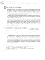
T
EXTURE INTRODUCTION
Textures are images applied to surfaces that are created using primitive objects.
The wide variety of texture attributes within the XNA platform gives developers
the power to blend and manipulate textures to create an infinite number of exciting
visual effects. For example, textures can be colored, filtered, blended, and trans-
formed at run time. Considering the importance of quality texturing, it’s no sur-
prise that XNA offers impressive support for presenting and manipulating texture
data. XNA supports .bmp, dds, .dib, .hdr, .jpg, .pfm, .png, .ppm, and .tga image
formats for textures.
UV Coordinates
UV coordinates specify a point in the texture; they are commonly referred to as tex-
ture coordinates. Texture coordinates are different from X, Y, and Z position coordi-
nates because a texture is a two-dimensional object that is mapped onto a
three-dimensional polygon. The texture’s two-dimensional coordinate data is stored
inside the vertex along with each X, Y, and Z position coordinate. When a texture is
mapped on a one-to-one basis to a rectangular object, both U and V coordinates take
a minimum value of 0 and a maximum value of 1. Figure 9-1 shows the UV coordi-
nate settings of textures that are mapped on a one-to-one basis in three different
planes.
C# Syntax for Textures
Textures are loaded and manipulated in C# using a Texture2D object. The object is
declared with the following syntax:
Texture2D textureObject;
121
Using the ContentManager Class
to Load Textures
The ContentManager class is an XNA component used for loading binary content
such as images. To use the ContentManager, you are required to reference your
media content from the Content node of your project. Once images have been added
to your project, the ContentManager’s Load() method can load the image files
into Texture2D objects. The Load() method only requires the directory path and
image name. The image file extension (*.bmp for example) is not required. In this ex-
ample, the Images folder is located in the Content folder, which can be found in the
same directory as the C# source files. The syntax shown here is used to load an image
from the game project’s Images folder within the project’s Content node:
Texture2D texture = Content.Load<Texture2D>("Images\\imageName");
CHAPTER 9
Texturing Your Game World
FIGURE 9-1
UV coordinates when mapping textures on the X, Y, and Z axes
Vertex Types for Textures
Previous examples used a
VertexPositionColor
variable for storing vertex
data. This variable type lacked the ability to store image information, so until now,
the 3D graphics have been limited to basic shapes and colors. Three vertex formats
allow for storage of image coordinates; they will literally add another dimension to
your graphics:
VertexPositionColorTexture This format allows you to apply image textures to
your primitive shapes, and you can even shade your images with color. For example,
with this vertex type you could draw a rectangle with an image texture and then you
could show it again with a different shade of color. The vertex variable declaration
syntax is:
VertexPositionColorTexture vertex = new
VertexPositionColorTexture(Vector3 position, Color color, Vector2 uv);
VertexPositionNormalTexture
This format allows you to add textures to your prim-
itive objects. The normal data enables lighting for this textured format. The vertex
declaration syntax is:
VertexPositionNormalTexture vertex = new
VertexPositionNormalTexture(Vector3 position, Vector3 normal, Vector2 uv);
VertexPositionTexture
This format only permits storage of position and texture
data. It may be useful if you don’t need lighting and were concerned about saving
space or improving performance for large amounts of vertices. The vertex declara-
tion syntax is:
VertexPositionTexture vertex = new
VertexPositionTexture(Vector3 position, Vector2 uv);
Shader Implementation for Textures
Texturing is applied in the shader. The shader code needed to texture objects is simi-
lar to the shader explained in Chapter 6. However, some changes to the code are re-
quired to enable textures. The additions required are:
A global
Texture
variable
A Sampler object for filtering the texture
MICROSOFT XNA GAME STUDIO CREATOR’S GUIDE
122