Interfacing PIC Microcontrollers 25 pptx
Bạn đang xem bản rút gọn của tài liệu. Xem và tải ngay bản đầy đủ của tài liệu tại đây (245.87 KB, 10 trang )
digital conversion. Suitable signal conditioning may be needed using ampli-
fiers, filters and so on, to produce a clean signal, controlling noise, drift, inter-
ference and so on, with the required output range.
Sensors have certain characteristics which should be specified in the data
sheet:
• Sensitivity
• Offset
• Range
• Linearity
• Error
• Accuracy
• Resolution
• Stability
• Reference level
• Transfer function
• Interdependence
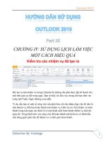
The meaning of some of these is illustrated in Figure 10.2.
SENSITIVITY
The ideal sensor characteristic is shown in the characteristic y ϭ m
1
x. The sensor
has a large change in its output for a small change in its input; that is, it has high
Interfacing PIC Microcontrollers
226
Output
Input
y = x
y = m
2
x
% error
y = m
1
x
high sensitivity
y = m
3
x + c
1
constant error
y = -m
4
x + c
2
negative sensitivity
c
2
c
1
y = ke
-ax
non-linear
Reference level, r
0
c
0
Range limited
linearity
Figure 10.2 Sensor characteristics
Else_IPM-BATES_ch010.qxd 7/11/2006 2:55 PM Page 226
sensitivity. The output could be fed directly into the analogue input of the MCU.
The line also goes through the origin, meaning no offset adjustment is required –
a linear pot would give this result. If the sensor has low sensitivity (y ϭ m
2
x), an
amplifier may be needed to bring the output up to the required level.
OFFSET
Unfortunately, many sensors have considerable offset in their output. This means,
that over range for which they are useful, the lowest output has a large positive
constant added (y ϭ m
3
x ϩ c). This has to be subtracted in the amplifier interface
to bring the output back into the required range, where maximum resolution can
be obtained. The same can be achieved in software, but this is likely to result in a
loss of resolution. Temperature sensors tend to behave in this way, as their char-
acteristic often has its origin at absolute zero (Ϫ273°C). The sensor may have off-
set and negative sensitivity, such as the silicon diode temperature characteristic
(y ϭϪm
4
x ϩc
2
). In this case, an inverting amplifier with offset is needed.
LINEARITY
The ideal characteristic is a perfect straight line, so that the output is exactly
proportional to the input. This linearity then has to be maintained through the
signal conditioning and conversion processes. Metal temperature sensors tend
to deviate from linearity at higher temperatures, as their melting point is ap-
proached, which limits the useful range. The deviation from linearity is usually
expressed as a maximum percentage error over the specified range, but care
must be taken to establish whether this is a constant over the range, or a pro-
portion of the output level. These two cases are illustrated by the dotted lines in
Figure 10.2, indicating the possible error due to non-linearity and other factors.
REFERENCE LEVEL
If the sensitivity is specified, we still need to know a pair of reference values to
place the characteristic. In a temperature sensing resistor (TSR), this may be
given as the reference resistance at 25°C (e.g. 1 k). The sensitivity may then
be quoted as the resistance ratio – the proportional change over 100°C. For a
TSR, this is typically 1.37. This means that at 125°C, the resistance of the 1 k
sensor will be 1.37 k.
TRANSFER FUNCTION
Linear sensors are easier to interface for absolute measurement purposes, but
some that are non-linear may have other advantages. The thermistor, for example,
has a negative exponential characteristic, but it has high sensitivity, so is often
used to detect whether a temperature is outside an acceptable range. If the sensor
is to be used for measurement, the transfer function must be known precisely in
order to design the interface to produce the correct output.
Sensor Interfacing
227
Else_IPM-BATES_ch010.qxd 7/11/2006 2:55 PM Page 227
ERROR
Many factors may contribute to sensor error: limitations in linearity, accuracy,
resolution, stability and so on. Accuracy is evaluated by comparison with a stan-
dard. A temperature of 25°C is only meaningful if Celsius is an agreed scale, in
this case based on the freezing and boiling points of water. Resolution is the de-
gree of precision in the measurement: 25.00°C (ϩ/Ϫ0.005) is a more accurate
measurement that 25°C (ϩ/Ϫ0.5). However, this precision must be justified by
the overall precision of the measurement system. Poor stability may appear as
drift, a change in the sensor output over time. This may be caused by short-term
heating effects when the circuit is first switched on, or the sensor performance
may deteriorate over the long term, and the measurement become inaccurate.
Recalibration of accurate measurement systems is often required at specified
intervals, by comparing the output with one that is known to be correct.
Interdependence in the sensor may also be significant; for example, the output
of a humidity sensor may change with temperature, so this incidental variable
must be controlled so that the required output is not affected.
Sensor Types
There is an enormous range of specialist sensors developed for specific ap-
plications in the engineering field. Some of the more commonly used sensors
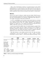
will be outlined here. Table 10.1 shows some basic position sensing devices,
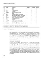
Table 10.2 different temperature sensors and Table 10.3 light, humidity and
strain measurement techniques.
Position
POTENTIOMETER
A potentiometer can be used as a simple position sensor. The voltage output
represents the angular setting of the shaft. It has limited range (about 300°) and
is subject to noise and unreliability due to wear between the wiper contact and
the track. There are therefore a range of more reliable position transducers,
which tend to be more expensive.
LVDT
A linear variable differential transformer (LVDT) uses electromagnetic coils to
detect the position of a mild steel rod which forms a mobile core. The input
coils are driven by an AC signal, and the rod position controls the amount of
flux linked to the output coil, giving a variable peak–to-peak output. It needs
a high-frequency AC-supply, and is relatively complex to construct, but reli-
able and accurate.
Interfacing PIC Microcontrollers
228
Else_IPM-BATES_ch010.qxd 7/11/2006 2:55 PM Page 228
229
Transducer Description Applications Evaluation
Linear potentiometer Linear position sensing Physical wear causes
Resistive track with Faders and multi-turn,
unreliability, but cheap
adjustable wiper pre-sets, medium-scale
and simple.
position. DC supply linear displacement.
across track gives a
variable voltage at
the wiper representing
absolute linear position.
Rotary Rotary position Physical wear
potentiometer sensing causes unreliability,
Rotary version senses Manual pots and
but cheap and
absolute shaft position pre-sets, any shaft
simple. Wire wound
as voltage or with a range of
are more robust, but
resistance (connect movement less than
may have limited
one end an wiper 300 degrees. May be
resolution.
together to form two used with float for liquid
variable resistance). level sensing.
Log scaling also
available.
Capacitor plate Linear position
No physical
separation sensing
contact, so more
Capacitance is Sensitive transducer
reliable. Needs more
proportional to plate for small changes in
complex drive and
separation (d is position. Plate overlap
interfacing.
normally small) Small can also varied,
change in d gives a although change may
large change in be less linear
C. Requires a high due to edge effects.
frequency drive signal
to detect changes in
reactance.
Capacitor dielectric Level or position No physical
sensing contact, so more
Capacitance depends The dielectric
reliable Needs more
on dielectric material, may be any insulating
complex drive and
effectively producing material, liquid or
interfacing involving
two capacitors in powder. A solid
AC to DC conversion
parallel whose values dielectric can detect Simple to construct.
add. Requires a high linear motion
frequency drive signal as its position is varied.
to detect changes in
reactance.
Magnetic flux Position/motion sensing Versatile sensor,
The flux linkage, Magnetic circuits can be
pulse detector is
therefore the output used in various ways to
simple, but flux
voltage varies with the detect position, motion,
linkage types may
position of the ferrite or vibration. Linear
need more complex
core Alternatively, the voltage differential
drive and detector
measured inductance transformer, electric
Involving AC to DC
of a single coil will guitar pick-up, rev
conversion.
increase as the ferrite counter (magnet on
is inserted further. A shaft ϩstationary coil).
permanent magnet may No physical contact
be used to create a required.
pulse of current as it
moves past a coil.
Table 10.1 Position sensors
+V
0V
Vo
+V
0V
Vo
C ∝ d
d
I
ac
Variable
Level
Air
Dielectric
˜
Input I
ac
Output V
ac
Coil
Core
Core
Else_IPM-BATES_ch010.qxd 7/11/2006 2:55 PM Page 229
230
Transducer Description Applications Evaluation
Metal resistance Temperature Metal resistance sensors operate
temperature sensor measurement over a wide range of temperatures,
A metal film or solid sensor Measurement over the
but may suffer from non-linearity
has the linear characteristic range Ϫ50°C to 600°C.
at outside a limited range
shown (within limits). The The Self-heating may
Sensitivity low, but
offset must be compensated be significant, as
inexpensive and
in the amplifier interface. reasonable current is
large range.
The sensitivity is typically needed to reduce noise.
of the order of 4 /°C.
Thermistor High temperature
The main advantage
sensing
is high sensitivity,
The thermistor is a solid
It is typically used in
that is, a large
semiconductor whose resistance
applications such as
change in resistance
falls rapidly with temperature
detecting overheating
over a relatively
increase. Following a
in system components
small temperature
negative exponential curve.
such as transformers
range. However, it
The rod is large and design
and motors, triggering
is non-linear, making
for high current use,
load shedding or
it difficult to obtain
while the bead is small
shutdown, up to about
an absolute temper-
and responds rapidly
150°C.
ature measurement.
to temperature change Therefore, most
over the range above useful for limit
room temperature. sensing.
Thermocouple High temperature The interface is complex, requiring
measurement cold junction temperature control
This is based on the junction of two
As the sensor is all
and a high-gain amplifier.
dissimilar metals, e.g. iron and
metal, high temperatures
This is worthwhile because the
copper, generating a small
can be measured.
output is accurate over a
voltage, as in a battery.
An interface with a
wide range of temperatures.
The large offset voltage from
high gain (instrumentation)
each junction is cancelled out by
amplifier is needed.
connecting the measuring junction
The interface is usually
(hot) and another (cold)
provided in the form of a
thermocouple in opposite polarity.
self-contained controller, with
Only the voltage difference
cold junction temperature
due to the temperature
control and curve
difference then appears at the
compensation.
terminals.
Silicon diode Temperature sensing
This can be used as a cheap
The volt drop across a A simple signal diode
and simple temperature sensor.
forward biased silicon can be used An
Probably best used for level
diode p–n junction interface amplifier will
detection, but is surprisingly
depends on be needed giving a
accurate if used in a carefully
temperature, dropping gain of about Ϫ10
designed circuit.
by about 2 mV/°C. (inverting), with offset
A constant current is adjust. In addition,
needed, as the volt a constant current
drop also depends source should used
on this. to supply the diode.
Integrated Temp Temperature This is a versatile
sensor measurement sensor, and the first
This is based on silicon General purpose low
choice for a low cost,
junction temperature temperature sensing
low temperature
sensing. An amplifier is with reasonable
MCU-based system.
built in, giving a calibrated accuracy. Can be
It is easy to interface,
output of typically operated from ϩ5 V,
does not need
10 mV/°C, over the so is easy to intergrate
calibrating and is
range of Ϫ50 to ϩ into digital systems.
inexpensive.
150°C. The accuracy
Response may be
is around ϩ/Ϫ 0.5°C.
slow due to size.
Table 10.2 Temperature sensors
Rod
Bead
Temp. (T)
R
R= ke
−βT
Hot (V
h
)
Cold (V
c
)
V
d
V
d
= V
h
- V
c
V
d
I
d (Constant)
V
d
Temp
0.6V
-2mV/°C
+5V 0V
10mV/°C
Resistance
R = αT + c
R
Temp.
Else_IPM-BATES_ch010.qxd 7/11/2006 2:55 PM Page 230
231
Phototransistor Light sensing
A high sensitivity
The phototransistor The transistor provides detector, but difficult
has no base connection, inherent gain (about to obtain a calibrated
but it is exposed to 100) making the device output. It is therefore
light by transparent quite sensitive. It is more frequently used
encapsulation. The incorporated in opto in digital systems for
base current is generated -couplers and detectors, isolation and
by light energy absorbed which usually use position/speed
by the charge carriers. infra-red light from measurement using
With a load resistance, an LED, which reduces a counter.
the collector voltage interference from
varies with base current visible light sources.
in the usual way.
Light-dependent Light measurement
The CdS cell
resistor
provides an accurate
The LDR uses a CdS The LDR is the standard output over a wide
(cadmium disulphide) cell cell used in light meters and range, but interfacing
which is sensitive to visible cameras, since photographic for a calibrated
light over a wide range exposure is also calculated output via an MCU
from dark to bright sunlight. on a log scale A coarse level requires conversion
If the light input (lux) voltage can be obtained of the log scale,
and resistance are with a simple series either via an
plotted on decade scales, resistance e.g. dark, accurate log amplifier
a straight line is obtained. overcast, sun. or in software.
Humidity Humidity measurement
Plain sensors requiring
A capacitor with an Environmental monitoring is the an HF AC signal to drive
absorbent dielectric general area of applications, the detection system
can vary in either for weather recording, available, or devices with
capacitance value product testing or production integrated signal conditioning
depending on the control. are simpler to interface.
humidity of the
surrounding air.
Strain gauge Stress, strain, position
Relatively simple and
measurement
reliable method of
This is simply a folded Typically used to monitoring small
conductor mounted on measure the mechanical defor-
a flexible sheet whose deformation in a mations. The high
resistance increases mechanical component gain amplifier is
as it is stretched. It is under load (e.g. crane susceptible
frequently used in jib) for safety monitoring to noise and
groups of four where purposes. Can also be interference, and
the pairs on opposite used to measure motion may need careful
sides of the bridge are at the end of fixed circuit design
mounted on the same beam to measure to obtain a stable
side of a component force applied or weight output.
under extension, and A high gain, differential
the other pair on the (instrumentation)
opposite side which is amplifier is needed.
under compression,
so that the differential
voltage is maximised
Pressure Differential pressure
Piezoresistive
measurement
sensors, accurately
If a set of strain gauges For measurement trimmed during
are mounted on both relative to atmosphere manufacture, and
sides of a diaphragm one side of the gauge integrated amplifier
as shown, they will will be exposed to provide accurate
respond to deformation atmosphere, the other output over selected
as a result of a differential to higher-pressure air ranges.
pressure. The output voltages or gas. If a vacuum
from each pair can be is used on one side,
added to give a absolute pressure
measurement. may be gauged.
Table 10.3 Other sensors
Net pressure
R
Vo
+5V
0V
Log L
Log R
Vd
+5V
0V
Bridge
output
Strain
Absorbent
dielectric
Transducer Description Applications Evaluation
Else_IPM-BATES_ch010.qxd 7/11/2006 2:55 PM Page 231
232
CAPACITOR
The capacitor principle provides opportunities to measure distance and level. If
considered as a pair of flat plates, separated by an air gap, a small change in the
gap will give a large change in the capacitance, since they are inversely propor-
tional; if the gap is doubled, the capacitance is halved. If an insulator is partially
inserted, the capacitance also changes. This can make a simple but effective
level sensor for insulating materials such as oil, powder and granules. A pair of
vertical plates is all that is required. However, actually measuring resulting
small changes in capacitance is not so straightforward. A high-frequency sens-
ing signal may need to be converted into clean direct voltage for input to a dig-
ital controller.
ULTRASONIC
Ultrasonic ranging is another technique for distance measurement. The speed
of sound travelling over a few metres and reflecting from a solid object gives
the kind of delay, in milliseconds, which is suitable for measurement by a hard-
ware timer in a microcontroller. A short burst of high-frequency sound (e.g. 40
kHz) is transmitted, and should be finished by the time the reflection returns,
avoiding the signals being confused by the receiver.
Speed
DIGITAL
The speed or position of a DC motor cannot be controlled accurately
without feedback. Digital feedback from the incremental encoder described
above is the most common method in processor systems, since the output
from the opto-detector is easily converted into a TTL signal. The position
relative to a known start position is calculated by counting the encoder
pulses, and the speed can then readily be determined from the pulse
frequency. This can be used to control the dynamic behaviour of the motor,
by accelerating and decelerating to provide optimum speed, accuracy and
output power.
ANALOGUE
For analogue feedback of speed, a tachogenerator can be used; this is essen-
tially a permanent magnet DC motor run as a generator. An output voltage is
generated which is proportional to the speed of rotation. The voltage induced
in the armature is proportional to the velocity at which the windings cut across
the field. This is illustrated by the diagrams of the DC motor in Chapter 8. If
the tacho is attached to the output shaft of a motor controlled using PWM, the
Interfacing PIC Microcontrollers
Else_IPM-BATES_ch010.qxd 7/11/2006 2:55 PM Page 232
tacho voltage can be converted by the MCU and used to modify the PWM out-
put to the motor, giving closed loop speed control. Alternatively, an incremen-
tal encoder can be used, and the motor output controlled such that a set input
frequency is obtained from the encoder.
Temperature
Temperature is another commonly required measurement, and there is variety
of temperature sensors available for different applications and temperature
ranges. If measurement or control is needed in the range of around room tem-
perature, an integrated sensor and amplifier such as the LM35 is a versatile
device which is easy to interface. It produces a calibrated output of 10 mV/°C,
starting at 0°C with an output of 0 mV, that is, no offset. This can be fed
directly into the PIC analogue input if the full range of Ϫ50°C to ϩ150°C
is used. This will give a sensor output range of 2.00 V, or 0.00 V – 1.00 V
over the range 0–100°C. For smaller ranges, an amplifier might be advis-
able, to make full use of the resolution of the ADC input. For example, to
measure 0–50°C:
Temp range ϭ 50°C
Input range used ϭ 0Ϫ2.56 V (8-bit conversion, V
REF
ϭ 2.56 V)
Let maximum ϭ 2.56 ϫ 20 ϭ 51.2°C
Then conversion factor ϭ 2.56/5.12 ϭ 50 mV/°C
Output of sensor ϭ 10 mV/°C
Gain of amplifier required ϭ 50 mV/10 mV ϭ 5.0
A non-inverting amplifier with a gain of 5 will be included in the circuit (see
Chapter 7). Note that if a single supply amplifier is used, the sensor will only
go down to about ϩ2°C.
DIODE
The forward volt drop of a silicon diode junction is usually estimated as 0.6 V.
However, this depends on the junction temperature; the voltage falls by 2
mV/°C as the temperature rises, as the charge carriers gain thermal energy, and
need less electrical energy to cross the junction. The temperature sensitivity is
quite consistent, so the simple signal diode can be used as a cheap and cheer-
ful alternative to the specialist sensors, especially if a simple high/low opera-
tion only is needed. A constant current source is advisable, since the forward
volt drop also depends on the current.
Sensor Interfacing
233
Else_IPM-BATES_ch010.qxd 7/11/2006 2:55 PM Page 233
METALS
Metals have a reasonably linear temperature coefficient of resistance over
limited ranges. Metal film resistors are produced which operate up to about
150°C, with platinum sensors working up to 600°C. The temperature coeffi-
cient is typically around 3–4000 ppm (parts per million), which is equivalent
to 0.3%/°C. If the resistance at the reference temperature is, say, 1 k, the
resistance change over 100°C would be 300–400 . A constant current is
needed to convert the resistance change into a linear voltage change. If a 1
k temperature-sensing resistor is supplied with a constant 1 mA, the volt-
age at the reference temperature, 25°C, would be 1.00 V, and the change at
125°C would be 370 mV, taking it to 1.37 V. An accuracy of around 3% may
be expected.
THERMOCOUPLE
Higher temperatures may be measured using a thermocouple. This is simply a
junction of two dissimilar metals, which produces a battery effect, producing
a small EMF. The voltage is proportional to temperature, but has a large offset,
since it depends on absolute temperature. This is compensated for by a cold
junction, connected in series, with the opposite polarity, and maintained at a
known lower temperature (say 0°C). The difference of voltage is then due to
the temperature difference between the cold and hot junctions.
THERMISTOR
Thermistors are made from a single piece of semiconductor material, where
the charge carrier mobility, therefore the resistance, depends on temperature.
The response is exponential, giving a relatively large change for a small
change in temperature, and a particularly high sensitivity. Unfortunately, it is
non-linear, so is difficult to convert for precise measurement purposes. The
thermistor therefore tends to be used as a safety sensor, to detect if a compo-
nent such as a motor or transformer is overheating. The bead type could be
used with a comparator to provide warning of overheating in a microcontroller
output load.
Strain
The strain gauge is simple in principle. A temperature-stable alloy conductor
is folded onto a flexible substrate which lengthens when the gauge is stretched
(strained). The resistance increases as the conductor becomes longer and thin-
ner. This can be used to measure small changes in the shape of mechanical
components, and hence the forces exerted upon them. They are used
to measure the behaviour of, for example, bridges and cranes, under load, often
for safety purposes. The strain gauge can measure displacement by the
same means.
Interfacing PIC Microcontrollers
234
Else_IPM-BATES_ch010.qxd 7/11/2006 2:55 PM Page 234
The change in the resistance is rather small, maybe less than 1%. This sits on
top of an unstrained resistance of typically 120 . To detect the change, while
eliminating the fixed resistance, four gauges are connected in a bridge arrange-
ment and a differential voltage is measured. The gauges are fixed to opposite
sides of the mechanical component, such that opposing pairs are in compres-
sion and tension. This provides maximum differential voltage for a given strain.
All the gauges are subject to the same temperature, eliminating this incidental
effect on the metal conductors. A constant voltage is supplied through the
bridge, and the difference voltage fed to a high gain, high input impedance am-
plifier. The instrumentation amplifier described in Chapter 7 is a good choice.
Care must be taken in arranging the input connections, as the gauges will be
highly susceptible to interference. The amplifier should be placed as near as
possible to the gauges, and connected with screened leads, and plenty of signal
decoupling. The output must then be scaled to suit the MCU ADC input.
Pressure can be measured using an array of strain gauges attached to a di-
aphragm, which is subjected to the differential pressure, and the displacement
measured. Measurement with respect to atmosphere is more straightforward,
with absolute pressure requiring a controlled reference. Laser-trimmed piezore-
sistive gauge elements are used in low-cost miniature pressure sensors.
Humidity
There are various methods of measuring humidity, which is the proportion of
water vapour in air, quoted as a percentage. The electrical properties of an
absorbent material change with humidity, and the variation in conductivity or
capacitance, can be measured. Low-cost sensors tend to give a small variation
in capacitance, measured in a few picofarads, so a high-frequency activation
signal and sensitive amplifier are needed.
Light
There are numerous sensors for measuring light intensity: phototransistor, photo-
diode, light-dependent resistor (LDR, or cadmium disulphide cell), photovoltaic
cell and so on. The phototransistor is commonly used in digital applications, in
opto-isolators, proximity detectors, wireless data links and slotted wheel detec-
tors. It has built-in gain, so is more sensitive than the photodiode. Infra-red (IR)
light tends to be used to minimise interference from visible light sources, such as
fluorescent lights, which nevertheless, can still be a problem. The LDR is more
likely to be used for visible light, as its response is linear (when plotted log R vs.
log L) over a wide range, and it has a high sensitivity in the visible frequencies.
The CdS cell is widely used in photographic light measurement, for these reasons.
Conversion into a linear scale is difficult, because of the wide range of light
intensity levels between dark and sunlight.
Sensor Interfacing
235
Else_IPM-BATES_ch010.qxd 7/11/2006 2:55 PM Page 235