CREATING GAME ART FOR 3D ENGINES- P5 docx
Bạn đang xem bản rút gọn của tài liệu. Xem và tải ngay bản đầy đủ của tài liệu tại đây (1.96 MB, 30 trang )
layers pallet as often as you might think; consider working without these tools while
you are painting your images and using the I key to activate the ink dropper and
the B key to switch to using the brush. Use the Alt+Tab key combination to bounce
between 3ds Max and Photoshop.
Using Layers for Flexibility
Layers tend to be underused in Photoshop. Just as in other software solutions, layers
add power and flexibility to your design process. With layers, you can move and
manipulate different aspects of your design separately. Without layers, you commit
too quickly to different changes and lose the flexibility to make further changes long
after the design is completed.
Using Layer Effects
There is a tremendous amount of power available in Layer Effects. Highlights, drop
shadows, bevels, and other effects can be set up and saved as a Layer Style and
easily applied to any other layer, in any file. Using Layer Effects, you can almost
instantly create shadowed and highlighted textures that look 3D. Many of the tex-
tures in this chapter utilize Layer Effects.
Using Layer Masks for Nondestructive Editing
When we erase a portion of an image for any reason, as soon as we save, those erased
pixels are gone forever. By using a Layer Mask, we preserve the entire image. If you
erase too much, Layer Masking allows you to paint it back in, even a year later. This
is because the Layer Mask allows you to paint-add or paint-subtract on an image,
using any size, style, or opacity of brush you prefer. Layer Masking is described in
more detail in the later section “Texturing the Oil Drum.”
Using Actions to Save Time
We can minimize repetition in Photoshop by using actions. Actions allow you to
record commands and then repeat that sequence of commands automatically as
needed by clicking a button. One of the processes that takes a lot of repetition is the
saving out of a PSD file so that you can check your texture in 3ds Max. Although
you cannot use the native PSD file for the actual texture in the game, it is sufficient
for checking how the texture is coming together on the model in 3ds Max. Usually
you will find something wrong with the texture, meaning you must go back and
tweak it, turn off the template layer, save the texture, take a look, turn on the tem-
plate layer, tweak again, and so on. Every time you do these types of tasks, it costs
you time. Making an action in Photoshop takes about one minute and pays for itself
the first day you implement it. For an action to work smoothly, you need to keep
your templates on a standard layer name, like template. Use as many layers as you
98 Creating Game Art for 3D Engines
Chapter 4 Texturing Game Art 99
need to make the texture work; the texture as you see it, but with the template layer
turned off, is what you will have on your model when you are finished.
It is better to wait on actions until you are comfortable with the sequences you
are trying to automate. When you are ready to automate any task, the procedure to
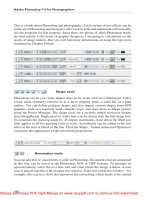
create an action is as follows (see Figure 4.1):
1. Make sure the Actions pallet is up.
2. From the flyout on the right, select Create New Action.
3. Give the action a name (call it SaveNoTemplate) and assign a function key
(F12).
4. Click the Record button.
5. Turn off the template layer.
6. Save the PSD file with Ctrl+S (so that you are not prompted for a name to
save to).
7. Turn on the template layer.
8. Click the Stop button at the bottom of the Actions pallet to stop the recording.
Make sure Toggle Dialog On/Off is turned off so that you will not be prompted
to name the exported file. You can find this toggle in the Actions pallet to the left of
each listed action.
If both Photoshop and 3ds Max are open and this action is implemented, you
will be able to change the texture while the template is visible and press F12 to see
an updated texture on your model. You can flip between Photoshop and 3ds Max by
using the Alt+Tab keys. Being able to see the results quickly and easily on the model
will improve your result. If you have a dual-screen setup, you can keep both appli-
cations visible at once and work even more efficiently.
Preparing the UV Template
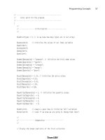
Figure 4.2 shows a basic template layer setup in Photoshop. The background layer
has been converted to a regular layer and renamed as template. A new layer was
created for the actual texture and thus named texture. The template layer has been
dragged above the texture layer so that it is on top. The Blend mode of the template
layer is set to Screen so that it shows through anything on the layers beneath it. You
can paint on the texture layer and still see the template. In this image, notice that
the template layer has been set to Screen mode and is positioned above the texture
layer. When your texture is ready, save it as a JPG or PNG file, with the template
layer turned off.
Remember that the template is like your canvas; the better the canvas, the bet-
ter the final texture can potentially be. The more important faces on the model
should receive the largest percentage of texture space, and the less visible or hidden
faces should receive the least. Overlap similar shapes where possible to save texture
space.
100 Creating Game Art for 3D Engines
FIGURE 4.1 Creating an action from the Actions window.
FIGURE 4.2 The template is set to Screen mode, and the texture is on the layer beneath it.
Chapter 4 Texturing Game Art 101
T
EXTURING THE
O
IL
D
RUM
The oil drum will be our first textured model. As you recall, we unwrapped the sides
of this model with a Cylindrical map and separated the top and bottom faces of the
model with a Planar map. Open OilDrumTemplate.tif (located in Files\OilDrum on
the companion CD-ROM) and walk through the steps described in the previous sec-
tion, “Preparing the UV Template in Photoshop.” We will apply a digital photo to the
oil drum as a Diffuse map; then we will alter a copy of the photo that we will use as
a Reflection map. This will cause the oil drum to partially reflect the sky in the game.
Because we are using a digital photo for the oil drum, we need to make sure it
works well flat. The oil drum presents some unique challenges in that the top, bot-
tom, and support ribs tend to distort depending on the angle the photo is taken
from. Figure 4.3 demonstrates with two inset images how much curvature there can
be to deal with on a photo of an oil drum. Taking multiple shots at different heights
and using only those portions of each image that have minimal curvature is one way
to arrive at a decent texture. You can also minimize curvature by taking the shot
with maximum zoom and then stepping back until the image is framed. In the back-
ground of this image is the finished texture, made up of multiple shots taken to min-
imize curvature and to collect overlapping images of the surface.
ON THE CD
FIGURE 4.3 The curves of the oil drum must be flattened.
Pushing Pixels with the Liquify Tool
You’ll need to modify many digital photos if you want to use them as suitable tex-
tures. One of the problems with the oil drum images is that the support ribs had too
much curvature. The Liquify tool in Photoshop, located on the Filters drop-down
menu, allows you to set a brush radius and then click-drag to push pixels in any
direction. In Figure 4.4, the Forward Warp tool button is turned on. The support rib
that the tool is over curves slightly downward. By carefully pushing pixels down in
the middle of the drum and pushing them up at the sides of the drum, you can flat-
ten the support rib for the texture. The Liquify tool, used with varying brush sizes,
made it possible to line up the support ribs and other curving edges in the photos.
102 Creating Game Art for 3D Engines
FIGURE 4.4 The Liquify tool allows us to push pixels around.
Using Offset to Make the Texture Wrap
This particular texture only goes about halfway around the oil drum. Whether your
texture goes halfway around the cylindrical object or all the way around, you are
going to have to deal with seams. The Offset tool, located under Filters, Other, lets
you slide the texture around so you can get the seam out in the open where you can
camouflage it. In Figure 4.5, the Horizontal pixels have been adjusted so that you
can see the seam, which appears as a red vertical line on the left of the image. At this
point, the Liquify tool was used to push the ribs at each end of the texture a bit so
they would match up better. Then, by using the Clone Stamp tool, the seam was
blended away so that it was no longer obvious.
Repairing Seams with the Clone Stamp Tool
In Figure 4.6, three stages of work are shown. Notice that the Clone Stamp tool is
turned on in the floating toolbar at the left. In the first window at the left, two oil
drum photos have been laid together and positioned, now that their ribs and other
lines are nearly horizontal. At this point, the file has several layers. A seam is evident
down the middle of the image.
Chapter 4 Texturing Game Art 103
In the middle window, two white circles indicate where the Clone Stamp tool
was positioned to hide the seam. The circle on the left is where the Clone Stamp tool
was initialized (by holding down the Alt key and clicking), and the circle on the
FIGURE 4.5 The Offset tool allows you to slide the seam of a texture
around for easier blending.
FIGURE 4.6 Three stages of using the Clone Stamp tool to camouflage a seam.
right is where the tool started painting (click-drag, or use a digitizing tablet and
pen). This initialization and painting process copies the pixels from the initialization
point to the destination point; it hides the seam well, but it also creates duplicate
patterns that can detract from the believability of the texture.
In the window on the right, some of the duplicate patterns, as well as some of
the differences between the two sides of the image, have been cloned away. You can
do this by initializing the Clone Stamp tool in an area with consistent color and tex-
ture and then painting those pixels over an area that has a duplicate pattern. You
can also do it by turning the opacity or flow down and painting different pixels over
one another, although this kind of camouflage can lead to blurriness. The initial
seam and the bottom ring of the drum were done at 100 percent opacity. The other
work was done at varying degrees of opacity and flow, sometimes cloning pixels
from one side to the other side of the image to improve overall consistency so that
the two would look more like one image. This image could still be improved upon,
but you need to consider how important and visible it is in the scheme of the game
and keep in mind that when it is scaled down to game size, many details will be lost.
At this point, the basic texture is done. You can add this texture to your Mater-
ial Editor using the same technique presented in Chapter 1, “Introduction to 3ds
Max,” for creating a custom material.
Reflection Mapping in Photoshop
If you want your object to map the environment in Torque, you can add reflectivity
to the material. If all you are after is an overall reflection, there is no need to do any-
thing more to your map in 3ds Max other than check the Reflection box in the Maps
rollout of the Material Editor in 3ds Max and assign a value. A value of 100 percent
will give you a completely reflective object, similar to placing a mirrored object in
the scene. The sky of your scene will reflect in the material. This method of general
reflection does not require that you assign a bitmap to the None button in the Maps
rollout of 3ds Max.
You can use Layer Masking and alpha channels to build the Reflective map into
a single image file. Figure 4.7 demonstrates this technique of adding reflection to a
texture. First, in Photoshop, copy your main texture layer and desaturate it. In this
example, the upper-left window is the start point. The image in the window to the
right has been desaturated. Adjust the Brightness/Contrast until those values suit
the amount of reflectivity you would like to achieve. Whiter areas reflect more,
whereas darker areas reflect less. Hand-paint or dodge and burn areas if necessary.
The third window, at the lower right, has had the grayscale image adjusted to fairly
heavy contrast so that the black areas will not reflect at all.
Now copy the contents of this desaturated layer by using Select All, creating a
Layer Mask in your primary texture layer, and selecting the Channels tab. Turn on
and select the Layer Mask channel. Paste the grayscale image you recently copied
onto the Layer Mask channel. At the upper right of this figure, you can see what the
Channels tab should look like at this stage. Click the Layers tab and then click the
104 Creating Game Art for 3D Engines
Chapter 4 Texturing Game Art 105
layer’s thumbnail. (The thumbnail is the picture of the actual image for that layer.)
Make sure that only this key layer is turned on when you save out a PNG file. At the
lower right of the figure is a screen shot of how this should look. The template layer
is turned off, the grayscale layer is turned off, and the original texture layer is turned
off. Only the layer named Tex + Alpha is turned on; this layer is a copy of the origi-
nal texture layer, with the grayscale selection pasted into its alpha channel.
Defining a Reflective Oil Drum Material in 3ds Max
After you’ve defined the material in Photoshop, it’s time to bring it into a sample slot
in 3ds Max and further define it. In the Material Editor, you can apply your texture
to a Diffuse map and to a Reflective map.
Dragging a Copy of the Diffuse Map to the Reflective Map Slot
Figure 4.8 shows three stages for adding material with the alpha channel content to
the Material Editor in 3ds Max. In the first stage, the material is applied to the dif-
fuse channel as usual, but in the Maps rollout, drag a copy of the material from the
Diffuse map to the Reflection map. When prompted as to whether you would like a
copy or an instance of the material, choose Copy, because you want to make sepa-
rate adjustments to the Reflective map here. Click on the Reflection map to change
FIGURE 4.7 The stages of creating a Reflection map for the oil drum.
its parameters. (See the white arrow in the first image.) This takes you down a level
in the Material Editor where parametric adjustments can be made to specific
bitmaps.
106 Creating Game Art for 3D Engines
FIGURE 4.8 For reflectivity to work, you must select it in Mono Channel Output.
Changing Mono Channel Output to Alpha
In the second image, you can see that the focus is on the Bitmap Parameters rollout;
in the Mono Channel Output group, click the Alpha radio button. Note here that the
Alpha Source group is set to Image Alpha. You can then click the Go to Parent button
(see the white arrow in the second image) to return to the main material interface.
Assigning the Material and Turning On the Show Map in Viewport Button
In the third image, you are back at the top level of the Material Editor, where you
can select the object and complete the normal process of clicking Assign Material to
Selection and Show Map in Viewport so that the material is assigned to your already-
unwrapped and ready model. This process for defining a reflective material is the
same if you want the material to be partially opaque; the main difference is that for
opacity, you would drag and drop the diffuse material to the Opacity map slot in-
stead of the Reflective map slot.
Chapter 4 Texturing Game Art 107
Assigning Smoothing Groups to the Oil Drum
Smoothing Group modifications for the oil drum include selecting all the cylindrical
faces and, under the Polygon Properties section, assigning them to Smoothing Group
1, selecting the top of the oil drum and assigning those faces to Smoothing Group 2,
and selecting the bottom of the oil drum and assigning those faces to Smoothing
Group 3. After all three sets of faces are on different smoothing groups, you should
have smooth cylindrical walls on the drum and realistic edges at the top and bottom
where the Smoothing Groups change.
All oil drum–related files are available in Files\OilDrum on the companion
CD-ROM.
T
EXTURING THE
H
EALTH
P
ATCH
The main body of the health patch is a textured steel base, generated with various
Photoshop filters; the raised portions of the texture were done with Layer Effects.
Creating Textured Steel
By applying four filters to a gray background, you can create an interesting texture
for the main body of the health patch. The filter that makes this texture take on 3D
proportions is the last one, Lighting Effects. The first three filters are there merely to
give this final filter something to work with.
1. Fill the canvas with Gray using the Paint Bucket tool, with RGB values of
R:123, G:123, and B:123.
2. Click the Filters drop-down menu, click Noise, Gaussian and set to 10%.
3. Click Filters, Blur, Gaussian and set blur to 3.5.
4. Click Filters, Artistic, Fresco, and set Brush Size to 2, Brush Detail to 8, and
Texture to 1.
5. Reapply a Gaussian blur and set it to 3.5.
6. Click Filters, Render—Lighting Effects. Set Style to 2 o’clock Spotlight. Make
sure the Spotlight covers the entire page. Set Light Type to Spotlight. Set the
color to light blue (189,230,251 RGB). Set Intensity to 10, Focus to 91, Gloss
to 59, Material to 82, Exposure to 26, Ambience to 24, Color RGB value to
255,254,199, and Height is set to 78. The Texture Channel is set to Blue, and
White is set to High.
TexturedSteel.psd is available in Files\HealthPatch on the companion CD-ROM.
Applying a Layer Style to Create Raised Steel Panels
Layer Styles are a powerful and simple way to create raised, highlighted, and shaded
images. In Figure 4.9, the base material is textured steel. This base material layer can
ON THE CD
ON THE CD
be copied by right-clicking over the layer and selecting Duplicate Layer from the right-
click menu. In the figure, this layer is called panels. You can add a Layer Style to this
layer by clicking the Add a Layer Style button at the bottom of the Layers pallet.
108 Creating Game Art for 3D Engines
FIGURE 4.9 Using Layer Styles with Layer Masks to paint in panels.
Following are the settings for the raised panel Layer Style:
• Drop Shadow. Blend Mode is set to Multiply, color is black, Opacity is 25%,
Angle is 30 degrees, Use Global Light is checked, Distance is 15 pixels, Spread is
0%, Size is 73 pixels, Contour is Linear, Anti-Aliased is not checked, Noise is
15%, and Layer Knocks Out Drop Shadow is checked.
• Outer Glow. Blend Mode is Color Burn, Opacity is 25%, Noise is 15%, RGB is
255,255,190, Technique is Softer, Spread is 0%, Size is 46 pixels, Quality is Lin-
ear, Anti-Aliased is turned off, Range is 50%, and Jitter is 0%.
• Inner Glow. Blend Mode is Vivid Light, Opacity is 92%, Noise is 19%, RGB is
190,190,190, Technique is Softer, Source is Edge, Choke is 0%, Size is 54 pixels,
Quality is Linear, Anti-Aliased is turned off, Range is 40%, and Jitter is 0%.
• Bevel and Emboss. Style is Inner Bevel, Technique is Smooth, Depth is 131%,
Direction is Up, Size is 6 pixels, Soften is 0 pixels, Angle is 30 degrees, Use Global
Light is checked, Altitude is 30 degrees, Gloss Contour is Linear, Anti-Aliased is
not checked, Highlight Mode is Screen, RGB is 255,255,255, Opacity is 75%,
Shadow Mode is Multiply, RGB is 0,0,0, and Opacity is 75%.
Using Layer Masking Instead of Erase
As you can see in Figure 4.9, the Layer Style has been applied; when this happens,
the Layer Style is applied to the entire layer. You can use a Layer Mask to help man-
age where there are pixels, and thus manage where the Layer Style is present.
Adding a Layer Mask to the layer allows you to paint away the entire image and
then add it back in, pixel by pixel. If you look at the Layers pallet, the panels layer
Chapter 4 Texturing Game Art 109
has two thumbnails; the one on the left is for the main texture, and the one on the
right is for the Layer Mask. When the Layer Mask thumbnail is active (as it is in this
image), your foreground and background colors in the toolbar are set to white and
black. You can paint with a white brush to add pixels to the layer, and paint with a
black brush to remove pixels from the layer.
One approach to paint a template precisely with Layer Styles and Layer Masks is
to make black the foreground color, paint the entire layer with the paint bucket,
switch the colors so that white becomes the foreground color, and then paint with the
brush. Painted pixels rise up with highlights and shadows, as shown in Figure 4.9.
To fill the template precisely, make the template layer current and use the Magic
Wand tool to select the inside of a boundary. After you’ve selected the area, click
Select, Modify, Contract to make the selection area smaller. Set the value to 1 or 2
pixels and click OK. Then make the panels layer current and fill the selection area
using the paint bucket. You can make refinements in this filled image by using the
brush. If you want to paint on the main texture, select the layer thumbnail first.
Animating a Pulsing Light Using an IFL Material
Creating any animated material using an Image File List (IFL) material is straight-
forward. An IFL file is an ASCII text file that creates an animation by listing a series
of single images that are displayed for the number of frames listed to the right of each
image name. For Torque, these images must be either JPG or PNG files; usually there
is a subtle transition where the images change as the sequence progresses. For
example, the colors of the images may slowly transition from blue to red. The IFL
file (pulse.IFL in this case) must have the following format:
pulse1.jpg 12
pulse2.jpg 2
pulse3.jpg 2
pulse4.jpg 4
In this example, four different JPG images will be displayed for the number of
frames shown at the end of each line. If any other animations are in the 3ds Max file,
you should adjust the total number of frames called out in a complete IFL cycle to
match or divide evenly into the number of frames in the asset animation. The health
patch is animated with 80 frames. In this IFL example, 20 frames are being used,
which will cycle exactly four times during one health patch animation cycle. Each of
the materials called out in the IFL should reside in the same folder as the IFL.
Animating a Transparent Exhaust Material
The exhaust for the health patch uses a gradient and ripple effect to look like gas
moving out of the bottom of the model. This texture also combines Opacity mapping
with animated IFL maps so that there is a moving, transparent flow coming out
under the main body of the model. Opacity is achieved in a method similar to the
way Reflection mapping is managed with the oil drum. The process used to make
this material semitransparent is demonstrated on the video SemiOpaqueMaterials.
wmv on the companion CD-ROM. This file is located in the Videos folder.
1. Open the 128 × 128 pixel exhaust template in Photoshop.
2. Set up the layers for a template, as discussed at the start of this chapter.
3. On your texture layer (let’s call it Layer 1), create a gradient between a light
blue foreground and a darker blue background (RGB 220,230,250 and
80,160,250). The gradient should be lighter at the top and darker at the
bottom.
4. Apply a filter to make the image add wave: Filter, Distortion, Ocean Ripple.
Set Ripple Size to 4 and Ripple Magnitude to 14.
5. Copy this layer and call it Grayscale. Desaturate it by going to Image, Ad-
justments, Desaturate.
6. With the Grayscale layer current, adjust Brightness/Contrast (Image, Ad-
justments) and adjust until the bottom of the image is completely black and
the top nearly white. Select, All and then press Ctrl+C to copy the contents
of the Grayscale layer. Now turn off the visibility of the Grayscale layer. You
are done with it.
7. Add a Layer Mask to Layer 1. Go into the Channels tab, and turn on the
visibility of the Layer Mask channel. Select the Layer Mask channel so that
it is the active channel.
8. Use Ctrl+V to paste the grayscale image you made. Go back to layers. Click
the thumbnail for Layer 1.
9. Select Layer 1, and click-drag until you are over the Create a New Layer
button. This creates a duplicate layer in the position over Layer 1. Rename
the new layer Layer 2. Repeat this process to create Layer 3 and Layer 4.
10. Select Layer 2 and activate the Move tool in the toolbar. Click three times
on your keyboard’s down arrow to move the layer contents down three pix-
els. Select Layer 3 and click six times to move the layer contents down six
pixels. Select and move Layer 4 down nine pixels.
11. Turn on Layer 1, and make sure all other layers are turned off. Save out the
file as exhaust1.png. Do the same for Layer 2, Layer 3, and Layer 4, creating
exhaust2.png, exhaust3.png, and exhaust4.png.
12. Using a text editor like Notepad, create a text file that looks like this:
exhaust1.png 2
exhaust2.png 2
exhaust3.png 2
exhaust4.png 2
13. Save the text file as Exhaust.IFL.
When you are finished, your layers should look like Figure 4.10. Only Layer 4 is
visible in this image so that you can see the image has been moved down; this is the
way the layers should be set up when exhaust4.png is saved out.
110 Creating Game Art for 3D Engines
ON THE CD
Chapter 4 Texturing Game Art 111
Applying the Materials in 3ds Max
Figure 4.11 shows the finished health patch, with the three textures applied. The top
of the health patch is a mesh named light, and it has the pulse IFL image applied.
The main body of the health patch is named body2, and it has the textured metal ma-
terial applied with Layer Styles to create raised paneling. The bottom of the health
patch is named exhaust, and it uses IFL animation as well as an Opacity map.
Simplifying the Scene When Working with Opacity
When working with Opacity maps for Torque Game Engine assets, it is a good idea
to work with just one visible object in the scene at a time. Testing and refining semi-
opaque materials in 3ds Max is difficult if more than one object is visible, because
you will see through one and into another, and the result will be confusing. To get
rid of distracting meshes, select the object you are working with, and from the right-
click menu, click Hide Unselected.
Using Mono Channel Output for the Exhaust Material Opacity Map
In Figure 4.11, the exhaust material is current in the Material Editor, and the Diffuse
and Opacity maps are evident in the Maps rollout; here an IFL (text file) is calling
four different PNG files in sequence. Just as with the reflective texture we used for
the oil drum, the Opacity map for this material has its Mono Channel Output value
set to Alpha.
FIGURE 4.10 The transparent exhaust material is set up for animation.
HealthPatchTextured.max and associated texture files are in the Files\HealthPatch
folder on the companion CD-ROM.
T
EXTURING THE
W
EAPON
For the weapon, you can use a metal texture for the stock of the gun and a gradient
color for the fins on the barrel of the gun. In Figure 4.12, an area of the gun texture
has been selected with the Polygonal Lasso tool. When the foreground color is gray
and the background color is white, you can achieve a three-dimensional effect by
using the Gradient tool, with the Reflected Gradient setting. The idea is to try to
make the gradients blend in to one another as you work your way across the gun, so
that the shape looks connected and continuous. The BlueBrushedMetal layer is
turned off in this image.
To create BlueBrushedMetal, follow these steps:
1. Start with a new file that is 300 × 300 pixels.
2. Use the Paint Bucket tool to fill the canvas with gray (RGB 150,150,150).
3. Click Filters, Noise, Add Noise—15%, Gaussian, Monochromatic.
4. Click Filters, Blur, Motion Blur and set to 45 pixels.
5. Change the Canvas Size to 256 × 256.
6. Click Image, Mode, and set it to RGB Color.
7. Click Image, Adjustments, Hue/Saturation, and adjust so that Hue is 210,
Saturation is 20, and Colorize is checked.
112 Creating Game Art for 3D Engines
FIGURE 4.11 The finished health patch uses meshes, each with its own material.
ON THE CD
Chapter 4 Texturing Game Art 113
FIGURE 4.12 You can use a reflected gradient to create a 3D effect for the weapon texture.
Figure 4.13 shows this process near the end, where the canvas is being resized
from 300 × 300 pixels to 256 × 256 pixels. This image is then selected, copied, and
pasted into the weapon texture.
FIGURE 4.13 Creating brushed metal with filters.
Pasting the brushed metal image into this texture has created a new layer (see
Figure 4.14). The layer is named and set to partial opacity over the gradients.
114 Creating Game Art for 3D Engines
FIGURE 4.14 Adding layers with partial opacity can add depth to the material.
In Figure 4.15, the final weapon texture has been created by adding panels, an
inset, text, and the steel plate material at partial opacity. A gradient colors the cool-
ing fins on the gun. You create the panels by selecting an area within the template
and adding a layer style.
FIGURE 4.15 Multiple, editable layers make this texture flexible for future editing.
Chapter 4 Texturing Game Art 115
Figure 4.16 displays the finished weapon texture. After you apply the texture,
you set the faces to smoothing groups so that neighboring, nearly coplanar faces are
set to the same group. Where the angles between faces is pronounced, different
smoothing groups accentuate edges.
FIGURE 4.16 The textured weapon with smoothing groups applied.
RaygunTextured.max and all associated texture files are located in Files\Raygun
on the companion CD-ROM.
T
EXTURING THE
P
OWER
C
HARGER
The power charger will be a mixture of concrete and steel. The concrete will be cre-
ated using filters only, and the steel will be based upon digital photos. In addition to
applying materials to the faces, smoothing groups can be adjusted to help define
faces and edges on the model, making the texture more believable.
Creating Concrete Using Filters
You can create concrete by starting with noise and blur. The Fibers filter creates the
effect of water running down a surface for years and discoloring it, but you should
use this only at partial opacity (see Figure 4.17). Dents are generated with the
Sponge filter, and Bevel and Emboss Layer Effects are added to the resulting selec-
tions to give them depth.
1. Create an image that is 256 × 256 pixels.
2. Fill with RGB 150,150,150 (light gray). Name this first layer
Base.
3. Click Filters, Noise and set to Gaussian at 5%.
4. Click Filters, Blur, Gaussian Blur and set to 1%.
ON THE CD
5. Create a new layer, filled with RGB 150,150,150. Name this layer Weathering.
6. Click Filters, Render, Fibers, and set Variance to 16 and Strength to 4.
7. Change Opacity on this layer to 25%, and desaturate it to suggest weather-
ing and streaking.
8. Create another layer, name it Dents, and use the Paint Bucket tool to fill it
with RGB 0,0,0.
9. Click Filter, Artistic, Sponge and set Brush size to 1, Definition to 25, and
Smoothness to 6.
10. Select the areas that are still black with the Magic Wand tool and delete them.
11. Change the Fill on this layer to 0%. Press Ctrl+D to deselect.
12. Add a Layer Effect—Bevel and Emboss. Set its parameters to Inner Bevel,
Smooth. Depth is 1, Direction is Down, Size is 1, and Soften is 2. Shading
Angle is 120 degrees, Global Light is checked, Altitude is 30 degrees, Gloss
Contour is Linear, Highlight Mode is Screen, Highlight Mode color is white,
Highlight Mode Opacity is 75%, Shadow Mode is Multiply, Shadow Mode
color is black, and Shadow Mode Opacity is 75%.
116 Creating Game Art for 3D Engines
FIGURE 4.17 Creating concrete using filters.
You can paint the textured metal over the concrete texture by entirely painting
out the overlay layer and then painting in the texture while Grid is turned on and
Snap To is set to Grid, to keep the brush strokes straight (see Figure 4.18).
Chapter 4 Texturing Game Art 117
Creating Ancient Metal
Sometimes the material you are looking for comes to you in an inconvenient form.
Floordrain1.jpg is a floor drain that seemed to have potential; unfortunately, it has
slots cut throughout its surface. Floordrain2.jpg is a version of the same drain that
has been repaired using the Clone Stamp tool.
1. Add GrimeMR2.psd to the image at 30% Opacity.
2. Choose Layers, Collapse Layers to merge the layers.
3. Apply the Plastic Wrap filter (Filters, Artistic) with a Highlight Strength of 4,
Detail of 14, and Smoothness of 2.
4. Adjust Hue/Saturation (Image, Adjustments), increasing Hue by 25 and de-
creasing Saturation by 15.
This creates AncientMetal.psd, which is used at the top of the power charger.
Layer Styles are used in the manner presented earlier to press and dent in the high-
lighted and shadowed material. This curves the material inward slightly so that the
rivet looks as though it compressed the material slightly when it was applied. All
of these materials are available on the companion CD-ROM. AncientMetal.psd is
located in Files\Powercharger, and the other files are located in Files\Misc.
FIGURE 4.18 You can paint the textured metal over the concrete using an Overlay layer.
ON THE CD
Modifying Smoothing Groups for the Power Charger
You need to adjust the Smoothing Groups to complete this model. Figure 4.19
shows two copies of the power charger side by side for comparison. It is easier to see
Smoothing Group issues on a nontextured model than on one that is textured. For
this reason, you may want to create a basic material and apply it while you are look-
ing for faces to put into Smoothing Groups.
118 Creating Game Art for 3D Engines
FIGURE 4.19 Setting appropriate Smoothing Groups for the nozzle of the power charger.
In this image, the right side of the nozzle of the power charger has been corrected,
and the left side still needs work. Note that the left side of the nozzle has obvious
faceting where two triangles form a polygon. You need to select both of these faces
and assign them to a Smoothing Group. Because groups 1–3 have already been taken,
these faces can be assigned to Smoothing Group 4. By going all the way around the
nozzle this way, you end up with a nozzle that has clean lines. It will look much better
with a texture.
When the model has good strong lines, and the edges are underlined because of
Smoothing Groups use, the texture can look its best (see Figure 4.20). But the ren-
dering you see in 3ds Max will always be slightly different from what you see in the
game engine. Keep your textures layered and flexible in case you need to make
changes after you’ve exported and analyzed your texture in the game.
Chapter 4 Texturing Game Art 119
T
EXTURING THE
A
MMO
B
OX
The ammo box is a simple texture that uses a billboard to achieve an in-game glow.
A billboard is an object that always faces toward the camera. You can create a plane
as a child to the ammo box. If the plane has a glow material on it, and the plane al-
ways faces the viewer, the glow appears to be real. To tell the Torque Game Engine
that your plane is a billboard object, add the prefix BB::.
The ammo mesh uses the same brushed metal technique as the weapon. A sym-
bol has been painted over the metal on one of the faces. If you want a pickup to
glow, you need to use the same method that you used for reflectivity and trans-
parency; in addition to the basic
texture layer, you need to add a Layer Mask and a
grayscale image to dictate which areas are transparent and which are opaque. This
Opacity map was created with the Gradient tool using the Radial Gradient setting,
with white in the foreground and black in the background. Figure 4.21 shows a
glow material for the ammo. Turn off all layers except the glow layer, and then save
the file as a PNG.
Figure 4.22 shows what the material looks like in the Material Editor in 3ds
Max. Similar to the method used for the health patch earlier in this chapter, the
FIGURE 4.20 The power charger after
smoothing and texturing.
PowerChargerTextured.max is available in Files\Powercharger on the companion
CD-ROM.
ON THE CD
120 Creating Game Art for 3D Engines
FIGURE 4.21 A radial gradient makes the ammo pickup appear to glow.
FIGURE 4.22 The glow for the ammo box uses an Opacity map and Self-
Illumination.
Chapter 4 Texturing Game Art 121
material is first applied to the diffuse map channel and then copied to the opacity
map channel, where Mono Channel Output is set to Alpha. In this figure, you can
also see that Self-Illumination is set to 100 percent. Self-Illumination is located
under the Blinn Basic Parameters rollout.
Figure 4.23 shows how to rotate the pivot point for the BB::plane. If a plane is
drawn while the back viewport is current, you can adjust the pivot point so that it is
oriented correctly to appear as a billboard in Torque. You do this from the Adjust
Pivot rollout of the Hierarchy panel, by turning on the Affect Pivot Only button and
rotating the pivot point –90 around the X axis. Notice at the top of this figure that
the reference coordinate system is set to Local in the Standard toolbar. The ammo
pickup with its billboard is on the left, and an unrotated plane has been placed to the
right for reference.
FIGURE 4.23 For this billboard to work correctly in the game, you need to rotate the pivot.
Figure 4.24 shows what this material looks like on the ammo pickup inside the
game. The glow draws attention to the pickup, and the billboard effect ensures that
the glow is always facing the player. If your billboard is not working, check that the
name of the plane you are using for the billboard starts with BB::, and rotate the
pivot of the plane properly.
The ammo model and all related textures are available in Files\Ammo on the
companion CD-ROM.
S
UMMARY
In this chapter, we discussed how to use digital photos to create your own custom
textures for metal and concrete. We looked at reflective and semiopaque materials
and how to create glowing materials. We explored IFL materials for making pulsing
lights and jet exhaust. In the next chapter, we will cover how to animate art assets
before you export them.
122 Creating Game Art for 3D Engines
FIGURE 4.24 A plane with a
BB:: prefix, partial opacity, and self-illumination seems
to glow.
ON THE CD