Essential LightWave 3D- P12 potx
Bạn đang xem bản rút gọn của tài liệu. Xem và tải ngay bản đầy đủ của tài liệu tại đây (1.46 MB, 30 trang )
placed straight down from the corner of
the mouth (when looking in the Back
viewport) and centered between the
first point and the last point of the
spline created in Step 28. Create a new
spline. This will act as the bottom of
our quad cage.
Since we now have top, right, and bottom
splines, we need to complete our quad cage
with a left spline.
30. In the Right viewport, create four new
points as shown in Figure 14-40. These
should start at the lower lip and run
down the profile, ending at the center
of the chin. The points should be posi
-
tioned at the very center of the head in
the Back viewport. Select all of the
points shown in the figure and create a
new spline.
Spin your model around in the Perspective
viewport and check for anything that looks
out of place.
We’ve expanded our spline cage, but the
area around the mouth is still open. Let’s
close that off. Considering that we already
have a top spline (created in Step 20), it
makes sense that we should create splines
for the bottom, left, and right to complete a
quad cage. However, there’s no need to
patch the region inside the mouth, and thus
there’s no need for a left spline. You can
create one if you like, but it won’t be used.
Hence, we simply need splines for the right
and bottom.
31. Create two new points as shown in Fig
-
ure 14-41. Select all three points as
shown and create a new spline. This
will be the right side of our quad cage.
Chapter 14
·······················
318
Figure 14-40
32. Create two additional points as shown
in Figure 14-42. Then select the points
shown and create a new spline. This
will be the bottom of our quad cage.
By adding these two splines, we’ve created
the inside boundaries for our face, but we’re
now in violation of Tips 2 and 3. The area
over the nose and cheek is much larger
than the other regions in our cage, and the
area around the jaw consists of more than
four splines. We need to address each of
these issues.
33. Select the existing points under the
nose and over the cheek as shown in
Figure 14-43 and create a new spline.
(If you don’t have the points needed to
····
Spline Modeling Exercise 2: Modeling a Human Head
319
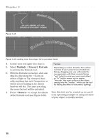
Figure 14-41: This small spline defines the corner of the mouth.
Figure 14-42
create this spline, you can add them by
selecting each spline and using the
Multiply | Subdivide | Add Points
tool.) This becomes the top spline of a
new quad cage.
34. Create two more points as shown in
Figure 14-44. Select all of the points
shown and create a new spline. This
becomes the right spline in our quad
cage.
Chapter 14
·······················
320
Figure 14-43
Figure 14-44
35. Create two points along the bottom of
the lower lip as shown in Figure 14-45.
Select all of the points shown and cre
-
ate a new spline. This becomes the
bottom spline in our quad cage. And
since the profile spline already exists, it
will act as the left spline, completing
the quad cage for this area.
We’ve partitioned off the area under the
nose and around the cheek, but it wouldn’t
hurt to break the entire area into smaller
sections.
36. Create a single point at the top of the
nostril where it indents and joins the
tip of the nose. Then select the exist
-
ing points as shown in Figure 14-46 and
create a new spline.
This becomes the top of
a new quad cage.
You’ll notice that this
new spline is not evenly
spaced between those
around it. As a result,
we have created a nar
-
row region running
over the tip of the nose
and down the side of
the face. This narrow
region violates Tip #3,
but the tightly spaced
polygons we’ll get by
patching this region are
necessary to properly
define the muzzle
region of the face.
····
Spline Modeling Exercise 2: Modeling a Human Head
321
Figure 14-45
Figure 14-46
37. Create two more points radiating out
from the corner of the mouth as seen in
Figure 14-47. Select all of the points
and create a new spline. This becomes
the right side of our quad cage.
38. Create two more points below the
lower lip as shown in Figure 14-48,
then select all of the points in order,
and create a new spline. This becomes
the bottom spline in our quad cage.
Once again, with the profile spline act
-
ing as the left spline, this completes
our quad cage.
Chapter 14
·······················
322
Figure 14-47
Figure 14-48
If you haven’t done so recently, now would
be a good time to spin your model and
check for anything that looks out of place. It
would also be a good time to save your
model.
You can really see the face starting to
take shape! But we still have areas that
consist of more than four splines
(specifically around the jaw and chin areas),
so we must partition these to create a quad
cage.
Looking at Figure 14-49, we can see that
two distinct edge loops converge at the jaw.
We need to section off the jaw so that each
of these loops can continue along its own
distinct path.
····
Spline Modeling Exercise 2: Modeling a Human Head
323
Figure 14-49: Two edge loops converge at the jaw, requiring us to divide
the area with a new spline.
Figure 14-50
39. Create three new points that follow the
jaw line as shown in Figure 14-50.
Select each of the highlighted points
shown in the figure and create a new
spline. You can see that each loop from
Figure 14-49 now has its own path to
follow.
Spin your model and check for anything
that appears to be out of place. Looking at
the cage, two things are pretty clear. First,
we’re almost done with the face. And sec
-
ond, we’re violating Tip #3. Although the
jaw now consists of a quad cage (where
each region is bounded by four separate
splines), the areas to be patched are much
larger than those around them. We’ll finish
the face by partitioning these areas.
40. Select the existing points shown in Fig
-
ure 14-51 and create a new spline.
Chapter 14
·······················
324
Figure 14-51
Figure 14-52
41. Select the existing points shown in Fig-
ure 14-52 and create a new spline.
42. Select the existing points shown in Fig-
ure 14-53 and create a new spline.
Zoom out and take a look at your spline
cage, correcting anything that seems out of
place. The face is now complete. All that
remains is to build splines for the back of
the head and neck, but if you’ve made it this
far, that will be a piece of
cake.
We can use the exist
-
ing cage as a starting
point for building the
remaining splines. But
with no ending point to
guide us, it’s difficult to
determine where each
spline should go. There
-
fore, we must develop a
basic framework to help
guide the placement of
each new spline. This
framework can be cre
-
ated from an outline of
the head and neck.
Take a look at Figure 14-54. The head
and neck can be broken down into one large
quad cage. There are distinct top, bottom,
left, and right sides. At this point, most of
the left side and part of the top already have
splines in place. We simply need to com-
plete the remaining splines to form a quad
cage around the entire region.
····
Spline Modeling Exercise 2: Modeling a Human Head
325
Figure 14-53
Figure 14-54
43. Create three more points at the center
of the head that run over the top
toward the back of the skull. Deselect
these points. Select the four points
shown in Figure 14-55 and create a
new spline. This completes the top
spline in our quad cage.
44. Create five more points running down
the back center of the head. Select all
of the points shown in Figure 14-56 and
create a new spline. This becomes the
right spline in our quad cage.
Chapter 14
·······················
326
Figure 14-55
Figure 14-56
45. Create six new points around the neck
running from the back to the front.
Then select all of the points as shown
in Figure 14-57 and create a new
spline. Make sure that you adjust the
points for this spline in both the Back
and Right viewports to ensure that the
spline forms a semicircular shape. This
becomes the bottom spline in our quad
cage.
46. Create a single point about halfway up
the center of the neck. Then select the
points shown in Figure 14-58 and cre
-
ate a new spline. This becomes the left
spline, completing our quad cage.
····
Spline Modeling Exercise 2: Modeling a Human Head
327
Figure 14-57
Figure 14-58
Having completed the framework, we can
wrap up our spline cage by playing “connect
the dots.” The existing splines on the face
end at an edge loop that runs over the fore
-
head, down the side of the head, and under
the chin. Each of these splines can be con
-
nected to the framework created in Steps
43 through 46. (See Figure 14-59.)
We could build each of
these splines as we’ve
done in the past by cre
-
ating “in-between”
points, then selecting
the points in order and
pressing <Ctrl>+
<p>. However, our
spline cage has become
fairly complex and this
will make it difficult to
position the in-between
points on the back of the head. As a result,
we’re going to use a different technique for
building these splines.
47. Select the two points shown in Figure
14-60 and press <Ctrl>+<p>to
create a new spline.
I mentioned at the beginning of this tutorial
that the most basic spline consists of three
points. Two act as endpoints, and the third
acts as a control point that allows you to
adjust the shape. We’ve just created a
two-point spline which, if you examine
carefully, is perfectly straight. It needs a
third control point to alter its shape.
48. Switch to Polygon Select mode. The
spline you just created should be high-
lighted. Navigate to the Multiply |
Subdivide menu and select the Add
Points tool. Click on the center of the
spline to add a third point. Then use
the Drag tool (<Ctrl>+<t>) to
adjust the shape of the spline. Make
sure you rotate your object in the Per-
spective view to check the shape of
this new spline. (See Figure 14-61.)
Chapter 14
·······················
328
Figure 14-59: The remaining splines can be
created by connecting those in the face to
those outlining the head and neck.
Figure 14-60
Note
You probably noticed that the region we
defined in Steps 47 and 48 has only three
sides (see Figure 14-62). Sometimes, no
matter how hard you try, it’s impossible to
create a quad cage. This is one of those
times. In circumstances like this, you should
do your best to position the three-sided cage
in a part of the model that will rarely be
seen (as we’ve done here).
49. Continue connecting the dots and add-
ing control points to create four more
splines as shown in Figure 14-63. Be
sure to check your model in the Per-
spective viewport after you shape each
new spline. Remember that the back of
the head is rounded at the top but
tapers as it approaches the neck. Your
splines should reflect this. If you feel
that you need additional
control points to help
maintain the shape of
the splines, feel free to
create them. (I’ve added
extra points to two of
the splines shown in
Figure 14-63.)
····
Spline Modeling Exercise 2: Modeling a Human Head
329
Figure 14-61: Add a third point to this spline and adjust its shape using the
Drag tool.
Figure 14-62
Note
You’ll notice that we are skipping over the
ears at this point. Ears can be created with
splines, but the process of linking them into
a larger spline cage can be tricky. As such,
we’re following Tip #1 by using splines to
create the overall form. The detailed process
of creating the ears will be covered in the
final section of this chapter using traditional
modeling tools.
At this point, we have another instance
where two edge loops converge at a large
empty space. (See Figure 14-64.) We need
to partition this space just as we did before
so that each loop can continue on its own
path.
Chapter 14
·······················
330
Figure 14-63
Figure 14-64: Two edge loops converge at the neck, requiring us to divide
it with a new spline.
50. Select the two endpoints shown in Fig
-
ure 14-65 and create a new spline.
Then use the Add Points tool to add a
central control point. Use the Drag tool
in the Back viewport to move this point
to the left slightly, creating a subtle arc
in the neck.
We have a nearly perfect quad cage, but the
back of the head and the neck are com
-
prised of areas that are much larger than
the rest of our cage. We must not forget Tip
#3! These areas should be divided into
smaller sections so that the same patch set
-
tings can be used on the entire model.
····
Spline Modeling Exercise 2: Modeling a Human Head
331
Figure 14-65
Figure 14-66: Keeping Tip #3 in mind, we must section off these large
areas by creating a new spline.
51. Select the existing points shown in Fig
-
ure 14-66 and create a new spline
running down the back of the head.
52. Create the three remaining splines
shown in Figure 14-67 using the tech
-
niques you learned earlier.
53. The last thing we need to do is section
off the neck so that its surface area is
not so large. Select the existing points
shown in Figure 14-68 and create a
new spline.
Chapter 14
·······················
332
Figure 14-67
Figure 14-68: Divide the neck area into two halves with this new spline.
Spin your model around in the Perspective
viewport and move any points that seem
out of place. If you feel that you need more
control over your splines, you can add
points to help adjust their shape. When
you’re finished, save a new version of your
model.
Before we wrap up this section, there are
two more things we should do.
The first is to run a Merge Points opera
-
tion on our model. As I mentioned earlier,
the number one cause of the “Curves Do
Not Cross” error is splines whose points
are not welded together. By running a
Merge Points operation, we can ensure that
any stray points are fused together and pre
-
emptively ward off this infamous error
message.
Press the <m> key to bring up the
Merge Points window. Accept the default
settings and press OK.
The second thing we should do is merge
a few of these splines. Take a look at Figure
14-69.
The image on the left shows two splines
that follow the same path from the top of
the eye to the back of the head. At the point
where these splines meet, there is a sharp
dip. This dip isn’t a major problem and
won’t affect our ability to patch this region,
but it will have a subtle effect on the overall
shape of our model. As such, it’s a good idea
to merge these splines together.
With the two splines selected, press
<Z> to merge them into a single spline.
The image on the right of Figure 14-69
shows the effect of merging these splines
together. Note that the slope is now much
more gradual.
You can continue working through your
spline cage at this point, merging splines
which, like those mentioned above, follow
the same basic path but meet at sharp
angles. The splines highlighted in Figure
14-70 are just a few of the ones I would rec-
ommend merging.
····
Spline Modeling Exercise 2: Modeling a Human Head
333
Figure 14-69
Note
Merging splines can be beneficial to the
overall shape of your cage, but it can also
be detrimental if taken too far and can ulti-
mately affect your ability to patch the cage.
For example, merging the profile splines
that run from the front of the head to the
back will cause havoc when you try to patch
your cage. As you merge your splines, keep
in mind Tip #2: Build quad cages. Try to
keep the top, bottom, left, and right splines
distinct from one another. Merging a Top
spline with a right or left spline could have
adverse effects. If you find that you are get
-
ting erroneous patches (or patches that
don’t fit the area you’re attempting to fill),
try splitting large splines into two or more
parts. You can do this by selecting the spline,
then switching to Points mode, selecting the
point where you’d like the split to occur, and
pressing <Ctrl> + <l>.
Note
At this point, I recommend saving your
object with a name such as “Generic Spline
Head Cage.” One of the great things about
modeling with splines is that a basic cage
can be used over and over to create similar
objects. In this case, a variety of head mod-
els can be created from this one basic cage.
Congratulations!! Using the tips and tricks
outlined earlier in this chapter, you’ve built
a very complex spline cage. This cage is not
only efficient, but it has exceptional flow —
one of the most crucial factors of a good
head model.
Chapter 14
·······················
334
Figure 14-70: Merge these splines to refine their overall shape.
Later in this chapter, we’ll patch the cage
and modify the results to ensure optimal
poly count. When you’re ready, save your
object with a new name and let’s begin by
learning about patching.
Patching Tips and Tricks
We’ve done a lot of work to get to this
point, but this is where our initial invest-
ment really pays off. Under normal
circumstances, patching our cage would
involve the tedious and painful process of
determining how many perpendicular and
parallel divisions to use for each section of
our cage. No more! Since we’ve built a quad
cage and partitioned it into similarly sized
segments, we can use the same patch set
-
tings for the whole object, making it a
relatively easy procedure. Easy, however,
does not mean foolproof. There are a num
-
ber of problems that can plague the
patching process. Therefore, before we get
started, I’m going to share a few more tips
and tricks with you.
•
Tip 1: Patch in the Perspective
viewport. Trying to select splines in one of
the orthographic viewports can be cumber
-
some. To make your life easier, I suggest
working directly in the Perspective
viewport. Click the Maximize Viewport
button to work full-screen within this view.
•
Tip 2: Patch in Wireframe mode. As
you patch your cage, each region will be
filled with polygons. Unfortunately, Modeler
treats splines as polygons. If your view type
is set to one of the shaded views (i.e.,
Smooth Shade, Flat Shade, or even Tex
-
tured Wire), Modeler will attempt to select
the polygons on top first and will skip over
the polygons on the bottom. As such, it can
be particularly difficult to select your
····
Spline Modeling Exercise 2: Modeling a Human Head
335
Figure 14-71: The cage we’ve just built can be quickly modified to create
other head models.
splines, especially as you get further along
in the process. Therefore, I suggest work
-
ing in the Color Wireframe mode. When in
the wireframe modes, Modeler does not
respect polygon order and will select every
-
thing your mouse moves over, not just the
polygons on top.
•
Tip 3: Use contrasting sketch colors.
The biggest pitfall of working in one of the
wireframe modes is that it can be difficult to
distinguish between your splines and your
polygons. To make this process easier, give
your spline cage one color and your polygon
wireframes another. To do this, go to the
Detail menu and under the Polygons head
-
ing, click on the Sketch Color tool. From
the pop-up menu, select Black as the sketch
color and click OK. Changing the sketch
color here will cause our spline cage to be
black when viewed in the Color Wireframe
mode. Now bring up the Display Properties
panel by pressing the <d> keyboard short-
cut. On the Layout tab, change Default
Sketch Color to White. By changing the
default sketch color, we are telling Modeler
to use white wireframes for all of our newly
created geometry. This division of color will
help us determine which polys are splines
and which are patches when viewed in a
wireframe render style.
•
Tip 4: If At First You Don’t Succeed,
Patch, Patch Again. The number one prob
-
lem that people run into when spline
modeling is the enigmatic “Curves Do Not
Cross” error. Often this results from splines
whose points aren’t welded together prop
-
erly. But sometimes it happens in spite of the
fact that everything has been done correctly. I
see questions like this posted online all the
time: “My points are welded but I’m still
getting the ‘Curves Do Not Cross’ error…
What’s wrong?” I honestly don’t know.
Sometimes Modeler is weird like that. But I
can tell you this: If you go back and select
your splines in a different order (even
reverse order), it will often work. I’ve run
into a number of cases where selecting top
(1), left (2), bottom (3), and right (4) will
give me an error, but selecting in a different
order, for example, left (2), bottom (3), right
(4), and top (1), will work. I can’t explain it.
I can only tell you that it works. It’s very
likely that you’ll be seeing the “Curves Do
Not Cross” error when you patch your head
model. If that happens, refer back to this
tip.
•
Tip 5: Don’t worry about spline selec-
tion order. To get the normals of your
polygons facing out, you must select your
splines in a counterclockwise order before
you patch them. But as we’ve seen in Tip
#4, there may be times when this results in
a “Curves Do Not Cross” error. Therefore,
don’t worry about the order in which you
select your splines. It’s easy to correct
polygons whose normals are facing the
wrong direction after the fact. For now, sim
-
ply patch and have fun.
Chapter 14
·······················
336
Patching the Cage
Let’s begin patching the cage. Make sure
that you’ve set your spline color to Black
and your default sketch color to White as
described in patching Tip #3. Then maxi
-
mize the Perspective viewport and change
the view mode to Color Wireframe. Hit
<a> to “fit all” so that our cage fills the
screen as shown in Figure 14-72.
You can begin anywhere you’d like, but
the area around the eye is a nice place to
start.
1. Select four splines in a clockwise or
counterclockwise order and press
<Ctrl>+<f> to bring up the Make
Spline Patch window.
Note
You can access the Make Spline Patch win
-
dow from the Construct | Patches | Patch
menu item, but I recommend using the
<Ctrl> + <f> keyboard shortcut as it will
save you a good deal of time.
2. The default for a spline patch is 10 Per
-
pendicular and 10 Parallel divisions
distributed over the Length of the
splines. However, 10 is far too many for
the cage we’ve built. Change each of
these to 2. Leave the distribution set to
its default (Length) and click OK. The
····
Spline Modeling Exercise 2: Modeling a Human Head
337
Figure 14-72: We’re ready to begin patching!
Figure 14-73: The proper patch settings.
splines will be patched with four new
polygons. Deselect the splines. Figure
14-74 shows the results of this new
patch.
3. Continue patching the edge loop
around the eye.
If, as you select your splines, you happen to
select a few polygons from one of your
patches, don’t worry. The Make Spline
Patch tool will ignore
any non-spline objects.
If you get a “Curves Do
Not Cross” error at this
point, there are several
things you should do:
a. Make sure that you
have four splines
selected (press
<i> to bring up
the Info window
and count the num
-
ber of curves
listed).
b. Make sure that you’ve selected your
splines in a clockwise or counterclock-
wise order.
c. Double-check that the points of each
spline are welded together.
If this doesn’t resolve the problem, see Tip
#4 above.
The results of patching this area are
shown in Figure 14-75.
Chapter 14
·······················
338
Figure 14-74: Our first patch.
Figure 14-75: The patched edge loop.
4. Continue working around the face of
your cage, adjusting your view as
needed in the Perspective viewport.
Note
Don’t patch the inside area of the eye. We’ll
build the inside of the eye with regular mod
-
eling tools later in the chapter.
5. When you’ve finished with the face,
start patching the neck.
6. Finally, work your way up the back of
the head.
Take a look at Figure 14-78. I’ve nearly
completed patching the head model, but the
region shown on the left side of the figure is
giving me a “Curves Do Not Cross” error
····
Spline Modeling Exercise 2: Modeling a Human Head
339
Figure 14-76: Continue patching the face section of the cage.
Figure 14-77: After you finish with the face, patch the neck.
when the splines are selected in the order
shown. I checked to make sure that four
splines were selected in a counterclockwise
order and that all their points were welded
together properly. Having worked through
the obvious solutions, it’s now time to try
patching Tip #4. By selecting the splines in
the order shown on the right side of the
Figure, I no longer get an
error message.
The last area to patch
should be the triangular
region at the top back of
the head shown in Figure
14-79. Since there are
only three splines here,
the order in which these
splines are selected will
affect the polygon layout
of our patch. In all hon
-
esty, you can select them
in any order you desire,
but to be consistent with
the work we’ll be doing
throughout the rest of
this chapter, select them in the order shown
in the figure.
Spin your model in the Perspective
viewport to check for any unpatched areas
in your cage. When your whole cage has
been patched, bring up the Statistics win-
dow by pressing the <w> keyboard
shortcut. If any splines are selected,
Chapter 14
·······················
340
Figure 14-78: This region will not patch properly, but following patching Tip
#4 enables me to work around the problem.
Figure 14-79: Patching the triangular region in the order shown on the left
yields the polygon layout on the right.
deselect them. Then press the “+” icon to
the left of the word “Faces.” This will select
all of the polygons in your head model. Cut
these and paste them into a new layer, leav
-
ing just the spline cage in this layer. Then
save your object.
Exit the full-screen Perspective view
and return to Modeler’s normal quad view.
Then change your Perspective view type
from Color Wireframe to Textured Wire. If
you see any blank or incorrectly colored
areas in your model (and you know that you
successfully patched those areas), it’s likely
that the normals for the polygons have been
flipped. Select these errant polygons and
from the Detail | Polygons menu select
the Flip command (or press the <f>key
-
board shortcut).
····
Spline Modeling Exercise 2: Modeling a Human Head
341
Figure 14-80: Select the polygons created by patching the cage, then cut
and paste them into a new layer.
Figure 14-81: Flip any polygons whose normals are facing the wrong
direction.
Congratulations on successfully patching
your spline cage! We can now mirror the
object to complete the basic head, but
before we do so we need to run the Merge
Points command again. As it stands, each
individual patch is a separate object. You
can see this for yourself by selecting any
single polygon and tapping the <]> (right
bracket) key to select the connected poly
-
gons. No more than four polygons will ever
be selected because each patch is its own
distinct object. In order to fuse the patches
together into one large object, we need to
merge points.
Press the <m> key to bring up the
Merge Points window. Accept the defaults
and press OK. A message should appear
saying that roughly 300 points have been
eliminated.
Let’s go ahead and mirror our object. To
successfully mirror the head, we need to
ensure that the points running down the
center are positioned exactly at 0 on the X
axis.
1. Click the Maximize button for the
Back viewport. This takes us to a
full-screen view. Tap the <a> key to fit
the object in our viewport as shown in
Figure 14-82.
We need a way to select all of the points
running down the center of our object, but
as you can see, there are a lot of points in
this region. Selecting them all by hand
would be a nightmare. To remedy this, we’ll
use Modeler’s Volume Select tools.
2. Press <Ctrl>+<j> twice to activate
Inclusive Volume Select mode.
(Pressing <Ctrl> + <j> once would
activate Exclusive Volume Select
mode.) Volume Select mode enables us
to drag a bounding box around the
polys or points we want affected. The
Inclusive option means that anything
partially inside the bounding box will
still be selected. Drag out a bounding
box as shown in Figure 14-83.
Chapter 14
·······················
342
Figure 14-82
Figure 14-83: Using the Inclusive
Volume Select tool, drag out a
bounding box that reaches just
inside your model.