Essential LightWave 3D- P2 ppt
Bạn đang xem bản rút gọn của tài liệu. Xem và tải ngay bản đầy đủ của tài liệu tại đây (1.62 MB, 30 trang )
Symmetry
The Symmetry action mode is one of the
handiest things to come along in LightWave
since its integration of OpenGL. With Sym
-
metry active, what you do to the right side
of your model is automatically mirrored to
its left side!
Note
Symmetry is a great tool, but to use it, you
must be immaculate in your modeling skills.
Symmetry only works when what is to the
left of X=0 is an exact mirror of what is on
the right of X=0 — just being close won’t do
a darn bit of good. (You can always mirror
your model if things get really out of whack.
There are also free “symmetry fixers,” but
they still require a fair amount of attention
to get things back on track.)
If you are planning to make something
that is symmetrical, start out with your base
form perfectly centered along the X axis, and
always make sure you have Symmetry active
when you are sculpting.
An odd thing about the Symmetry function
is that with it active, if you move something
with your mouse’s focus to the left of X=0,
its effect along the X axis will be
“backward.”
Action Centers
It’s easiest to understand action centers
when thinking about rotating something
that you have selected.
•
Action Center: Mouse — Wherever
your mouse is positioned becomes the pivot
around which your selection is rotated.
•
Action Center: Origin — When you
rotate your selection, the rotation will be
centered around X=0, Y=0, Z=0.
•
Action Center: Pivot — Your selec-
tion will be rotated around where you have
set that layer’s pivot point to be.
•
Action Center: Selection — The
rotation will be centered right in the middle
of your selection.
Chapter 2
························
18
Figure 2-34: Under the Modes pop-up menu are
selections to tell Modeler where you want your
actions to be centered.
Figure 2-33: With the Symmetry action mode
active, selecting the polygons on the right side of
the model’s nose automatically selects their
counterparts on the left side. Any tweaking of the
polygons on the right will automatically be
mirrored on the left.
Quick-Info Display
In the lower-left corner of Modeler is a
readout that quickly lets you know the
exact position of your mouse, how many
elements you have selected, and how much
area each grid square represents.
Modeler Toolsets
On the left-hand side of Modeler are the
toolsets. These toolsets are directly linked
to the tabs at the top of Modeler’s window.
When the Create tab is active at the top
of the screen, the toolset shown is Light-
Wave’s primary set of tools geared for the
creation of geometry.
Note
Anytime you see a pop-up menu with
“More” on it, that means there are addi
-
tional tools that aren’t being displayed
because of the screen size; you can access
these tools through the pop-up menu.
It’s a pretty simple way to think about it,
but you create “stuff” with the tools under
the Create tab (Figure 2-36) and you modify
that “stuff” with the tools under the Modify
tab. With these tools, you can move, rotate,
drag, bend, twist, size, and stretch elements
and generally “push points.”
Note
I imagine that it’s because of the vast array
of tools LightWave has in its arsenal that it
refrains from showing you pictures of
spheres, capsules, boxes, and metaballs.
Clicking on any one of these tools and then
click-dragging in the viewports will create
the geometry associated with that tool.
Remember that even though we’ll be get
-
ting into more detail with some of these
tools in later chapters and exercises, the best
way to get to know these (and all of
LightWave’s tools) is to play around with
them. If you’re wondering what a metaball
is, try it out; you’re not going to break any
-
thing by having a few metaballs floating
around on your screen.
The key is to have fun building “riffs” that
you can call on later when the need arises.
It may be years before you find a need for a
specific, rather arcane tool, but when that
need comes around, you can remember,
“Oh yeah, I think I saw something like
that…” and be able to zero in on it much
more quickly than paging through a manual
(or decrypting strange, iconic representa-
tions of abstract concepts).
The Modify tab (Figure 2-37) contains a col-
lection of tools that modify existing
geometry.
The Multiply tab (Figure 2-38) holds the
tools that take existing geometry and make
more of it (cloning or extruding, for
example).
The Construct tab (Figure 2-39) houses
tools that are useful as you continue to
refine and construct your geometry (such
as Booleans and point/polygon reduction).
The Detail tab (Figure 2-40) holds the
tools that focus on the more detail-oriented
bits of modeling. You can assign a sketch
color, fuse (weld) two vertices into one, and
add, remove, and reduce the edges of your
object.
···················
LightWave Dissected
19
Figure 2-35: Modeler’s Quick-Info display.
The Map tab (Figure 2-41) houses most
of the tools that you use to modify and
refine your VMaps. Using the tools in this
tab, you can create textures, morph targets,
and weight (influence) maps that will give
you tremendous control over your charac
-
ter animation.
The Setup tab (Figure 2-42) contains the
tools you’ll need to set up and modify a
character’s skeleton (used for character ani
-
mation) as well as adding gons (polygons
that can be converted to various objects
such as lights in Layout).
The Utilities tab (Figure 2-43) allows
you to add plug-ins and launch custom
scripts (known as LScript commands). The
Utilities tab also features a “catch-all”
pop-up menu called “Additional.” The
third-party plug-ins you bring into Modeler
will appear under this menu item.
Chapter 2
························
20
Figure 2-37: The
Modify tab.
Figure 2-39: The Construct tab.
Figure 2-36: The
Create tab.
Figure 2-38: The Multiply
tab.
Figure 2-40: The Detail tab.
The View tab (Figure 2-44) controls
zooming and panning. It lets you hide and
unhide selected elements and group poly
-
gons and points to quickly zero in on tight
areas of complex models. The View tab also
features several Layer tools to add, delete,
and merge the layers of your object.
···················
LightWave Dissected
21
Figure 2-41: The Map tab.
Figure 2-43: The Utilities tab.
Figure 2-42: The Setup tab.
Figure 2-44: The View tab.
Modeler General Options
LightWave’s Modeler keeps its options in
two separate locations. It has display
options (which we’ll get to in just a
moment) and general options. The General
Options window can be found under Edit |
General Options.
Hot Key Block
General Options
<o> brings up Modeler’s General Options
window.
The options in the General Options window
include:
•
Content Directory — This tells
LightWave the default root path to where
its models and scenes are kept.
•
Polygons — This tells LightWave
what base shape to use in geometry cre
-
ation whenever possible. Quadrangles work
best when creating sub-patch surfaces for
high-resolution models, while triangles
work best for many game engines.
•
Flatness Limit — This is a setting
you will probably never need to change
(I’ve never touched it in all my years of
using LightWave). It tells Modeler how
much deviation is acceptable among the
points that define a flat, planar polygon
before it is considered non-planar. (See
Figure 3-6.)
•
Patch Divisions — This tells Light
-
Wave how much of its geometric smoothing
algorithm to use when displaying sub-
patches. Higher numbers yield smoother
surfaces but are much slower to work with.
•
Undo Levels — This tells LightWave
how many levels of “Undo” to keep in
memory. (The default is 8. But I like a high
level so I can feel free to explore what
might turn out to be a blind alley and still be
able to get back to where I was when I
started that particular exploration without
having to revert to a saved version of my
object.)
The other options are fairly self-explana
-
tory, so I’ll let the LightWave manual cover
them — these are just the ones I’ve found
to be not really intuitive.
Modeler Display Options
The Display Options window is accessible
through Edit | Display Options.
Hot Key Block
Display Options
<d> opens Modeler’s Display Options
window.
Chapter 2
························
22
Figure 2-45: Modeler’s General Options window.
Figure 2-46: Modeler’s Display Options window.
Modeler offers a lot of customization for tai
-
loring itself to how you want your work
presented to you. When the Display
Options window is first opened, the Layout
tab is shown. With this tab, you set the gen
-
eral display options for all windows, unless
a window is specifically freed from these
generalizations under the Viewports tab.
One important thing to make note of is
that LightWave Modeler’s familiar “quad”-
style layout can be changed here by select
-
ing another style from the Layout pop-up
menu. Don’t get locked in to just using the
Quad layout out of habit. The other layouts
can be quite helpful.
Note
LightWave’s Viewport layout can be further
tweaked by clicking and dragging on the
bars that separate the viewports, resizing
them to your exact needs.
Figure 2-47 shows my personal preferences
for the Perspective viewport (located at the
top right by default).
•
Independent Center and Independ
-
ent Zoom let me pan and zoom around my
Perspective viewport without disturbing
the other viewports that I might have cen
-
tered in on some important details.
•
Independent BG Color has been
changed from LightWave’s hallmark gray to
dull blue. I almost never use that particular
shade of blue in my work, so my models
stand out against it.
•
Independent Rotation means that
any other Perspective viewports aren’t
linked to this one’s rotation. (This kind of
linkage can be helpful when you’ve got one
Perspective viewport showing the model in
Wireframe and the other in Smooth or
Weight Shade.)
•
Independent Visibility lets me see
what I want, when I want. Cages (the polyg-
onal base of sub-patches) get in my way
when working in shaded views, as do their
“guides.” Polygon normals also tend to get
in my way, so I’ve turned them off for this
view as well. I intermittently turn on and off
Show Point Selection and Show Polygon
Selection when it suits the detail work I’m
doing on a model.
The Backdrop tab (Figure 2-48) lets you put
a loaded image into the background of any
orthogonal viewport. This is helpful when
you’re building a model that references a
photograph or drawing. (We go through the
steps to do this in Chapter 10.)
The Interface tab (Figure 2-49) lets you
make some customizations to how Mod
-
eler’s interface looks. (I touch on how you
can really rework LW’s interface in just a
moment.)
···················
LightWave Dissected
23
Figure 2-47: Changing display options for
individual viewports.
Note
To be honest, the only changes I’ve ever
made to the Interface tab are to set Input
Device to Tablet and to change the Alert
Level. The Alert Level lets you set how
urgent an alert must be in order for it to ask
you to press OK to continue. (We get into
how Alert Level affects workflow later on in
the chapters on modeling.)
If you haven’t tried modeling with a tablet
device (Wacom is my personal favorite for
durability and precision), I highly recom
-
mend it. When you’re dragging points
around, your motions are a lot like drawing.
You simply touch the stylus tip down on a
point and drag and bring the stylus up off
the pad when the point is where you want it
to be. I find it to be so much faster than
clicking a mouse and a lot less painful. (And
because holding a “pencil” is more of a
natural position than holding a mouse, I
imagine that a tablet could be a help to
people worried about carpal tunnel syn-
drome — though this is only a guess.)
The Units tab (Figure 2-50) is the tab I use
most frequently in the Display Options win-
dow in Modeler. In this tab, you can tell
LightWave whether you want to work in
metric units or English units. More impor-
tantly, this tab is where you activate and
adjust Grid Snap.
LightWave’s quick and variable Grid
Snap is another one of those things that
you’ll wish every 3D program had. Its set
-
tings are as follows:
•
Standard lets you quickly position
objects with respect to decent-sized (one-
tenth) segments of Modeler’s visible grid.
•
Fine breaks Modeler’s Standard snap
into even smaller units for precise position
-
ing, still respecting units of its visible grid.
•
Fixed lets you specify exactly what
interval to which you wish to adhere your
movements, regardless of the visible grid.
•
None lets you move objects in utter,
minute detail.
Chapter 2
························
24
Figure 2-49: The Interface tab.
Figure 2-48: The Backdrop tab.
Figure 2-50: The Units tab.
Note
I usually find myself flipping between None
and Standard Grid Snap quite often while I
work.
Even though it might seem counter
-
intuitive, Grid Units actually has nothing to
do with Grid Snap. Grid Units controls the
zoom amount when you zoom by pressing
<,> and <.>.
The File Menu
In the upper-left corner of Modeler is the
File pop-up menu. Here, you will find the
Load, Save, Import, and Export commands.
The Edit Menu
The Edit pop-up menu, located just below
the File pop-up menu, provides traditional
edit functions (cut, copy, paste, etc.) as well
as access to the commands through which
you can customize almost every aspect of
Modeler. With the saving and loading of
preferences, keyboard shortcuts, and menu
layouts, you can take your personal
customizations with you wherever you go.
The Window Menu
Just below the Edit menu is the Window
pop-up menu. Here you’ll find access to
three additional panels that let you adjust
layers, modify VMaps, and manage surface
presets. You can also use this menu to hide
any floating windows and turn on and off
the toolbar.
···················
LightWave Dissected
25
Figure 2-51: The File pop-up menu.
Figure 2-52: The Edit pop-up menu.
Figure 2-53: The Window and Help pop-up menus.
Note:
If you turn off the menu toolbar and find
later that you don’t know how to turn it on
again, don’t panic! You can restore the
toolbar by using the <Alt> + <F2> key
-
board shortcut or by unchecking the Hide
Toolbar button on the Interface tab of the
Display Options panel (shortcut <d>).
The Help Menu
When you run into trouble or have ques
-
tions about a particular aspect of the
software, the Help menu (Figure 2-53) is
the first place to turn. The Help menu links
you to the online and web-based documen
-
tation. Completely rewritten for LightWave
8, these files contain a wealth of useful
information to aid in your understanding of
the software.
Modeler Quick Menus
The LW manual calls these “contextual
pop-ups.” I prefer the term “quick menu”
because that’s exactly what they are. You
hold <Shift> + <Ctrl> while left-, right-,
or middle-clicking in your workspace, and
these menus appear. (See Figures 2-54 to
2-56.) They let you do all sorts of things
you would normally have to sift through a
few layers of pop-up menus to get at.
(These menus are fully customizable, as are
all the other menus in LightWave — point
-
ers on how to customize menus follow in a
moment.)
Chapter 2
························
26
Figure 2-54: <Shift>+
<Ctrl>+left -click brings
up this menu.
Figure 2-55: <Shift>+
<Ctrl>+right -
click brings up this
menu.
Figure 2-56: <Shift>
+<Ctrl>+middle-
click brings up a quick
menu that covers just
about everything else
Modeler has a
command for.
Hot Key Customization
What if you come to LightWave already
accustomed to certain hot keys doing cer
-
tain things? No problem. You can assign and
reassign every command, script, macro,
etc., to a hot key!
If I wanted to assign Close All Objects to
the hot key <Ctrl> + <F12> (as in Fig
-
ure 2-57), I would do this:
1. Choose Edit | Edit Keyboard Short
-
cuts to bring up the Configure Keys
window, as shown in Figure 2-57.
2. Search through the commands in the
left-hand column (or use the Search
button on the right side of the window),
expanding the drop-down lists.
3. When you’ve found the command you
want to assign to the hot key, click on
it, highlighting it.
4. Scroll through the hot key list until
you’ve found the key you want to
assign.
5. Click on the desired hot key, highlight-
ing it.
6. Click on Assign to assign the com
-
mand to the hot key. (Clicking on
Unassign removes the command from
the key.)
7. Repeat as desired.
8. Click on Save and back up your hot
keys for those “CYA” kind of
happenings.
9. When you’re finished, click Done.
Note
Under the Presets pop-up menu are the
default hot key mappings, so you can go
crazy with your assignments if you like and
can always get back to the defaults should
you need to.
However, as nifty as interface customiz
-
ation is (hot keys or menu layouts), it makes
it really hard to use someone else’s version
if you ever get together with friends and
work on a film together. I found this out the
hard way starting my own studio. From
being an independent contractor, I had my
own license of LW so “tricked out” that the
first time I sat down at a new hire’s version, I
was almost completely lost with the default
hot keys and menu layouts.
A solution to this is to have your configu-
ration files where you can access them from
the Internet, or carry them around on one of
those keychain USB drives. But remember to
save your host’s configurations before you
load yours, and restore his configs when
you’re done.
Menu Layout Customization
If you want to completely rework Light
-
Wave’s menus or make a new plug-in easily
accessible as a button, you can do this just
as easily as assigning hot keys. You can add,
delete, and reorder the menu tabs across
the top of Modeler, keeping all your favorite
tools just a mouse-click away.
In Figure 2-58, you can see that the Ball
Tool command, located under the Create
drop-down list, has been given a menu
position just under Box (and renamed to
just Ball) under the Primitives group. By
···················
LightWave Dissected
27
Figure 2-57: Edit | Edit Keyboard Shortcuts brings up
the Configure Keys window.
comparing the actual menu and the Con-
figure Menus window, you can see how
each tool, group, tab, and menu is
configured.
This may be a bit confusing, so here’s
an exercise for you to get more of a han
-
dle on menu customization. Let’s add a
temporary menu and assign some tools
to it:
1. Activate the Configure Menus win
-
dow (Edit | Edit Menu Layout).
2. Collapse all the drop-downs except
the one for Main Menu. (You do this
by clicking on the little downward-
pointing triangles next to each main
group, circled in Figure 2-59.)
3. Select the View sub-group under
Main Menu, and click on New
Group. See Figure 2-60.
Chapter 2
························
28
Figure 2-59
Figure 2-60
Figure 2-61: A new group, labeled New Group, is created
directly below the previously highlighted group.
Figure 2-58: Edit | Edit Menu Layout brings up
the Configure Menus window.
A new group, labeled New Group,
is created directly below the previ
-
ously highlighted group.
4. Select New Group, and click on
Rename. Name this group any
-
thing you like (Figure 2-61).
5. Find the Ball Tool under the Cre
-
ate commands. Highlight it and
the new group you’ve just created
and renamed, and click on Add.
A new instance of the Ball Tool
now appears under the Deleteme
tab, as shown in Figure 2-63. (It
doesn’t disappear from where it
was under the Create | Primitives
Tab/Group. It just can now also be
found here, under this new tab
we’ve created.)
6. To organize your new menus, you
create groups and sub-groups.
With Ball in your new menu tab
selected, click on New Group
(Figure 2-64).
···················
LightWave Dissected
29
Figure 2-62
Figure 2-63
Figure 2-64
7. Highlight New Group, which is
created directly below the item previ
-
ously selected, and click on Rename
to change its name to whatever you’d
like. (See Figure 2-65.)
8. You can then drag the new tool, Ball,
onto the new group (which I named
Kemu) to assign it to that group. (See
Figure 2-66.)
Note
Notice that in Figure 2-66, there is a
blue line just below and slightly
shorter than Kemu. This line means
that the dragged item will be attached
to the item directly above the line. If
the blue line were to reach all the
way to the left side of the word
“Kemu,” that is LightWave’s indication
that the item being moved will simply
be shuffled below the item directly
above the line.
You have now created the Ball Tool under
the Kemu group in the new Deleteme
menu tab.
Chapter 2
························
30
Figure 2-65
Figure 2-66
Figure 2-67
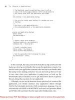
Layout
Layout is where you bring everything
together to create those incredible master
-
works you have in you. Layout is where
you position your objects, hang your lights,
and set your objects moving (if you’re
animating). After LightWave takes a
moment or so to render, out comes this
slick image for you to show off in e-mails to
all your friends (or print and tape to your
refrigerator, if that’s your kind of thing).
···················
LightWave Dissected
31
Figure 2-68: Layout has a lot in common with Modeler. The tabs, menu styles, viewport controls, and
Quick-Info display readout are all pretty much the same. The differences between Layout and Modeler are
so intuitive, you’ll get the hang of them without even realizing it.
Viewport Styles
The biggest differences between Modeler
and Layout viewports are that in addition to
viewing orthogonal and perspective projec-
tions, you can also set the view to see what
any of your cameras or lights are seeing or
view the contents of your scene as pre-
sented in a Schematic layout. Because
bones figure so heavily in character anima-
tion, Layout also adds two bone-specific
display types: Bone Weight Shade and Bone
X-Ray, which we touch on in just a moment.
Chapter 2
························
32
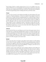
Figure 2-69: Layout’s viewport settings and display
type, called Maximum Render Level here, are
almost identical to Modeler’s.
Figure 2-70: Layout’s Bounding Box Maximum Render Level display does away
with all but the simplest geometry. Objects are represented only by a bounding
box that encompasses the object’s volume. (Bones, lights, cameras, and other
“iconic” items are shown normally.)
Figure 2-71: Layout’s Vertices Maximum Render
Level shows only the points in the objects.
Figure 2-72: Layout’s Wireframe and Front Face
Wireframe are similar to Modeler’s Wireframe and
Hidden Line display types. Front Face Wireframe
speeds refresh rates (how quickly LightWave is able
to redraw the screen) and decreases clutter by not
bothering to draw any polygon facing away from
the viewport (knowing which way a poly is
“facing” is explored in Chapter 3 in the section on
normals).
Viewport Controls
The viewport controls in Layout are almost
exactly the same as Modeler’s. Move (Pan),
Rotate (Orbit), Zoom, and Min/Max all do
exactly the same thing. The one change to
the viewport controls is the addition of the
little symbol on the left that looks like a
registration mark. That symbol is a toggle
button that activates Center Current Item.
When active, LightWave will center that
viewport in all three dimensions around
your current item’s pivot point.
Note
You can activate Center Current Item to find
an item and then deactivate it, moving your
view around to bring in things on the
periphery.
It’s easy to forget you’ve got Center Cur
-
rent Item active when you get into noodling
details. If Center Current Item is active when
you switch to another item, that new item
will then be centered in that viewport.
···················
LightWave Dissected
33
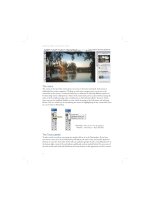
Figure 2-73: Layout’s Shaded Solid and Textured
Shaded Solid (not shown) are a little prettier than
Modeler’s because Layout’s takes into account up
to eight lights in its OpenGL rendering.
Figure 2-75: Bone X-Ray lets you see the bones
that might be hidden by the object’s geometry.
Figure 2-76: Bone Weight Shade shows the effect
your object’s bones have on its mesh. Colors are
determined by the bone’s color, and the blending
shows the effect of the various bone weight maps
that limit the bone’s influences.
Figure 2-77: Layout’s viewport controls.
Figure 2-74: Layout’s Textured Shaded Solid
Wireframe is similar to Modeler’s Textured Wire
view type.
Linking to Modeler
Layout’s link to Modeler is the Modeler
button in the upper-right corner of the win
-
dow. (This button is only visible when
running LightWave with the Hub active.)
When you click on this button, you are
taken to Modeler, and your most recently
selected object will be open and ready for
you to modify.
Chapter 2
························
34
Figure 2-80: The Modeler button.
Note
Moving and Rotating in Perspective
Viewports
LightWave has established a convention
about moving things in Perspective viewports
that doesn’t require you to have one hand on
the keys and the other on the mouse.
Moving an item or panning a viewport
while holding down the left mouse button
constricts movement to the X/Z plane.
Holding the right mouse button constricts
movement to the Y axis.
Rotating an item or orbiting a viewport
while holding down the left mouse button
rotates in heading and/or pitch. Holding
down the right mouse button rotates in
bank only.
In addition to using the viewport controls,
remember these quick ways of moving about,
identical to what we mentioned for Modeler’s
Perspective viewports:
•
To orbit about a Perspective viewport’s cen-
ter, hold <Alt> while dragging the mouse in
the viewport that you wish to examine (still
following the above rules for left and right
mouse buttoning).
•
To scroll (pan) the view in a Perspective
viewport, just as in Modeler, hold <Shift> +
<Alt> while dragging your mouse in the
viewport you wish to explore (still following
the above rules for left and right mouse
buttoning).
Figure 2-79
Figure 2-78
The Frame Slider
The Frame Slider is like a ruler for measur
-
ing time. The little thing that looks like the
shooter from Space Invaders is the slider
that controls which frame you are currently
viewing.
Note
The slider part of the Frame Slider always
shows the current frame. It can be set to
show that frame in frames (fractional and
whole), SMPTE time code, feet and frames
(film key code), and the scene’s time in sec-
onds.
You can find out how to set the Frame
Slider later in this chapter in the “Layout
General Options” section.
Frame Controls
In the lower right-hand corner of Layout is
a set of controls that you might find on a
high-end VCR. These controls let you play
your scene immediately (without having to
render anything), forward or backward, in
all viewports, respecting each viewport’s
Maximum Render Level.
You may not have seen Previous Key and
Next Key before. Keyframes are discussed
in Chapter 15, but for the moment, think of
a keyframe as telling the computer, “As you
move this item, make absolutely sure it
passes through this specific point and/or
this specific rotation.”
At the bottom of Figure 2-82 is the Step
input field. You can click in this area and tell
LightWave to play every frame (Step=1),
every other frame (Step=2), every third
frame (Step=3), etc. Increasing the Step
···················
LightWave Dissected
35
Figure 2-81: The Frame Slider is at the bottom of Layout’s viewport(s), sandwiched between input fields
for the start frame and end frame. (You can click in these fields and change how long your scene is;
negative numbers are okay.)
Figure 2-82: The Frame controls.
Figure 2-83: The Previous Key and Next Key
buttons.
can improve playback performance on com
-
plex scenes at the cost of playback accuracy.
At the left side of Figure 2-82 is the
(Animation) Preview pop-up menu. Build
-
ing and playing animation previews is
discussed in Chapter 15, so just store this
info away for later.
At the bottom of Figure 2-82, you’ll find
Layout’s Undo/Redo buttons. The number
of Undos available can be set in the General
Options panel (more on that later).
Hot Key Block
Time Controls
<Left Arrow> steps to the previous frame
of your scene. (At the first frame of your
scene, the Frame Slider “wraps around” to
the last frame of your scene.)
<Right Arrow> advances to the next frame
of your scene. (Again, at the end of your
scene, the Frame Slider “wraps around” to
the beginning.)
<Shift> + <Left Arrow> jumps to the pre-
vious keyframe of the currently selected
item.
<Shift> + <Right Arrow> jumps to the
next keyframe of the currently selected item.
Undo/Redo
<Ctrl> + <z> and <z> respectively
undoes and redoes what can be undone and
redone.
Key Creation/Deletion
Just to the left of the frame controls are the
buttons that let you create and delete
keyframes for your items.
Delete Key works the same as Create Key
(only it deletes keyframes, rather than cre-
ating them).
Note
You can enter any frame in the Create Key
At box. (You aren’t limited to creating
keyframes only on your current frame.)
For looping animations, I make sure the
scene’s “head” and “tail” match up by creat
-
ing a keyframe for all items on the last
frame of my scene, referencing the position
of everything on the first frame.
To do this, you move the Frame Slider to
the first frame of your scene, click on Create
Key, type in the number of the last frame of
the scene in the Create Key At box, and
choose All Items in the For pop-up menu.
Chapter 2
························
36
Figure 2-84: The Create Key
and Delete Key buttons.
Figure 2-85: Create Key brings up a window where
you can tell LightWave to remember the position,
rotation, and/or scale along any axis for your
choice of items.
The Auto Key button (see Figure 2-84),
when active, will automatically create
keyframes for any item you move, rotate, or
resize. This is a great thing for newcomers
to animation because it frees you from hav
-
ing to remember to create a keyframe for
your modified items before moving on to
the next frame or exiting Layout.
Note
The Auto Key function is actually a two-part
system. Auto Key will not work unless both
parts are active.
In addition to having the Auto Key button
active, you must also tell LightWave on
which channels (axes) you wish to create
keys — only the ones you’ve modified or all
channels.
You set this additional information in Edit
| General Options | Auto Key Create.
(I touch on this again later in this chapter
when we go over Layout’s general options
and when we work with animation in Chap-
ter 15.)
Item Selection
To help you navigate through scenes where
you have hundreds of objects (with a few of
those objects perhaps having a couple hun
-
dred bones), tens or hundreds of lights, and
two or more cameras, Layout automatically
“filters” that information for you.
When you have the Objects button
active, only objects will appear in the Cur-
rent Item pop-up menu. When you have the
Bones button active, only the bones of the
most recently selected object will appear in
the Current Item pop-up menu. Similar
rules apply to the Lights and Cameras
buttons.
Note
I’m going to skip over the Properties button
right now. Because there are so many varied
properties for each kind of item, it is best to
explore them in the chapters where we actu
-
ally use these properties in the exercises.
Directly above the Current Item pop-up
menu is a line of information that Layout
uses to keep you on top of what’s going on.
Information about using the current tool
can be found here, like “Drag mouse in
view to move selected items.” Error mes
-
sages also appear here. If something has
you stumped, take a peek here — there
might be a clue to unraveling your mystery
quietly sitting there.
···················
LightWave Dissected
37
Figure 2-86: Just to the left of the key creation/
deletion buttons are the controls that tell Layout
whether you want to manipulate the scene’s
objects, bones, lights, or cameras.
Quick-Info Display
Just like in Modeler, Layout includes a read
-
out of important information, such as
position, rotation, scale, how many items
you have selected, and how much area each
grid square represents, in the lower-left
corner of the window. (What is currently
shown as position information changes to
show rotation and scaling, etc., when Lay-
out’s active tool is changed.)
The one big difference between Layout’s
Quick-Info display and Modeler’s is that
Layout’s is interactive. You can enter data
into each of the X, Y, and Z fields, as is
being done with the Z axis in Figure 2-87.
You can also click on each individual X, Y,
or Z axis button (normally white with black
text) to protect it from accidental manipula
-
tion. This will deactivate the button, giving
it a blue background with colored text, as is
the case for the X axis in Figure 2-87. This
means that with the X axis protected, if I
were to left-click and drag to move my
selection, it would move only along the Z
axis, not along both the X and Z axes.
The Dope Track
Just above the Frame Slider but below the
viewport window lies a small gray bar.
Clicking the center of this bar will pop up
the Dope Track. (No giggles from the pea-
nut gallery, please!) The Dope Track is an
adjustment tool that can be used to quickly
create and modify your keyframes. We’ll
talk more about the Dope Track and its
cousin, the Dope Sheet, in Chapter 15.
Chapter 2
························
38
Figure 2-87: Layout’s Quick-Info display.
Figure 2-88: The Dope Track.
···················
LightWave Dissected
39
Layout Menu Tabs
With the Items menu tab (Figure 2-89)
selected at the top of the window, you are
presented with tools that let you load, add,
replace, and delete the different items in
your scene.
As with the other menu tabs in Layout,
I get into the more important pop-ups, win
-
dows, and tools as we use them in later
chapters. Just be aware that all this stuff is
here and waiting for you.
The Modify menu tab (Figure 2-90) con
-
tains tools to move, rotate, and resize the
objects in your scene. You’ll also find tools
to adjust keyframes and unleash the power
of LightWave’s Inverse Kinematics on your
characters (more on that in Chapter 16).
The Setup menu tab (Figure 2-91) gives
you access to LightWave’s powerful charac
-
ter rigging tools. If you’ve ever rigged a
character in another package, you know
Figure 2-89: The Items
menu tab.
Figure 2-90: The Modify menu tab.
Figure 2-91: The Setup menu tab.
Chapter 2
························
40
what a pain it can be. But these tools make
it a breeze to create, edit, adjust, and save a
character’s skeleton. We’ll be taking a
closer look at these tools in Chapter 16.
Note
The bottom viewport in Figure 2-90 shows a
Schematic view of all the items in the scene.
Schematics are covered in depth in Light
-
Wave 3D 8 Character Animation (Wordware
Publishing). In short, they help to break your
scene into bits and pieces that conform to
your personal preferences for visual
organization.
The Utilities menu tab (Figure 2-92) allows
you to add and remove plug-ins as well as
run your own custom scripts. The Utilities
menu in Layout is virtually identical to the
one in Modeler. (Easy, huh?) You’ll find the
tools here to do everything from writing
your own particle dynamics simulation
engines to crafting custom shaders, should
you ever feel so inclined. (There’s even a
robotic chess game and a Tetris clone
someone wrote using LScript — they both
play right inside Layout.) The Additional
pop-up menu here functions just like its
counterpart in Modeler and houses the
third-party plug-ins you’ve loaded into
Layout.
Figure 2-93: The Render menu tab.
Figure 2-94: The View menu tab.
Figure 2-92: The Utilities menu tab.
The Render menu tab (Figure 2-93) lets
you change settings in the Render Options
window (such as turning on raytracing and
choosing an output format for your anima
-
tion). You’ll also find tools to render individ
-
ual objects, single frames, or full
animations, and the ability to activate
LightWave’s Versatile Interactive Preview
Render (VIPER), which lets you see
changes to your surfaces in real time. Talk
about power!
The View menu tab (Figure 2-94) gives
you the ability to change your viewport
setup, adjust the grid, and make complex
selections.
The File Menu
The File menu in Layout has many of the
same functions as it does in Modeler.
Rather than repeat that information here,
I’ll touch on the more esoteric functions:
•
Load Items From Scene loads the
objects (and lights, if you wish) and all their
motions into the scene on which you are
currently working. This is a great way of
combining a complex scene for “in-camera”
rendering if you have broken it apart into
small, bite-sized pieces to work on it more
easily.
•
Load Object Layer lets you load just
a single layer from an object rather than
loading all its layers at once (which is what
Load Object will do).
•
Save Trans(formed) Object is some
-
thing I use a lot when I want to “freeze” an
object’s deformations, position, orientation,
and scale into a single object I can use in a
background layer for reference while
sculpting a model that will interact with it in
an animation. (This is what I did with the
sled-dog models in earlier illustrations.)
•
Save Motion File will save all of an
item’s movement, rotation, and scaling into
a single file, which you can then load onto
any other item.
•
Content Manager is a tool used to
consolidate the items in your scene and
gather all the resources used into one cen-
tral location. This can be a lifesaver when
you need to share your complex scenes
with others or simply need to port the
scene between work and home.
···················
LightWave Dissected
41
Figure 2-95: The File menu.
The Edit Menu
Like its counterpart in Modeler, the Edit
menu houses most of Layout’s customiz-
ation functions.
The Window and Help
Menus
The Window menu provides access to many
of Layout’s floating palette windows. The
Help menu offers local and web-based sup-
port options.
Layout Quick Menus
Chapter 2
························
42
Figure 2-96: The Edit menu.
Figure 2-97: The Window and Help menus.
Figure 2-98: <Shift>+
<Ctrl>+left -click opens
a menu that gives you
instant access to many of
Layout’s most frequently
used commands.
Figure 2-99:
<Shift>+<Ctrl>
+ right-click brings
up a menu that lets
you quickly launch
different editing
windows and select
from various
rendering options.
Figure 2-100:
<Shift>+<Ctrl>+
middle-click gives
you quick access to a
plethora of character
rigging tools.