Mạng VSAT (P1) pot
Bạn đang xem bản rút gọn của tài liệu. Xem và tải ngay bản đầy đủ của tài liệu tại đây (5.95 MB, 47 trang )
1
INTRODUCTION
This
chapter aims at providing the framework of VSAT technology in the
evolving context of satellite communications in terms of network configuration,
services, operational and regulatory aspects. It also can be considered by the
reader as a guide to the following chapters which aim at providing more details
on the most important issues.
1.1
VSAT
NETWORK
DEFINITION
VSAT, now a well established acronym for Very Small Aperture Terminal, was
initially a trade mark for a small earth station marketed in the
80s
by Telcom
General in the USA.
Its
success as
a
generic name probably comes from the
appealing association of its first letter
V,
which establishes a 'victorious' context,
or
may be perceived as a friendly sign of participation, and SAT which definitely
establishes a connection with satellite communications.
In this book, the use of the word 'terminal' which appears in the clarificationof
the acronym will be replaced by 'earth station', or station for short, which is the
more common designation
in
the field of satellite communications for the equip-
ment assembly allowing reception from or transmission to a satellite. The word
terminal will be used to designate the end user equipment (telephone set,
facsimile machine, television set, computer, etc.) which generates or accepts the
traffic that is conveyed within VSAT networks.
This
complies with regulatory
texts, such as those of the International Telecommunications Union
(ITU),
where
for instance equipment generating data traffic, such as computers, is named 'Data
Terminal Equipment'
(DE).
VSATs are one of the intermediate steps of the general trend in earth station size
reduction that has been observed in satellite communications since the launch of
the first communication satellites in the mid
60s.
Indeed earth stations have
evolved from the large INTELSAT Standard
A
earth stations equipped with
antennas 30m wide, to today's receive-only stations with antennas as small as
60
cm for direct reception of television transmitted by broadcasting satellites, or
hand held terminals for radiolocation such as the Global Positioning System
(GPS)
receivers. Prospects are for telephone handsets intended for satellite
personal communications
[MAR94].
VSAT Networks
G.Maral
Copyright © 1995 John Wiley & Sons Ltd
ISBNs: 0-471-95302-4 (Hardback); 0-470-84188-5 (Electronic)
2
Introduction
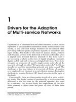
Figure
1.1
Trunking
stations
Therefore
VSATs
are at the lower end of a product line which offers a large
variety
of
communication services: at the upper end are large stations which
support large capacity satellite links. They are mainly used within international
switching networks to support trunk telephony services between countries,
possibly on different continents. Figure
1.1
illustrates how such stations collect
traffic from end users via terrestrial links that are part of the public switched
network of a given country. These stations are quite expensive, with costs
in
the
range of
$10
million, and require important civil works for their installation. Link
capacities are in the range of a few thousand telephone channels, or equivalently
about
100
Mb/s.
They are owned and operated by national telecom operators,
such as the
PTTs.
VSAT
network
definition
3
At the lower end are VSATs: these are small stations with antenna diameter less
than 2.4m, hence the name 'small aperture' which refers to the area of the
antenna. Such stations cannot support satellite links with large capacities, but
they are cheap, with manufacturing costs in the range of
$5000
to
$10
000,
and easy
to install any place, on the roof of a building or on a parking lot. Installation costs
do not exceed
$2000.
Therefore, they are within the financial capabilities of small
corporate companies, and can be used to set up rapidly small capacity satellite
links, in a flexible way. Capacities are of the order of a few tens of kb/s, typically
56
or
64
kb/s.
Referring to transportation, VSATs are for information transport, the equival-
ent of personal cars for human transport, while the large earth stations mentioned
earlier are like public buses or trains.
At
this
point it is worth noting that VSATs, like personal cars, are available at
one's premises. This avoids the need for using
any
public network links to access
1
F,
/I
I
It'
national
COUNTRY
A/
sr-estrial
link
l
l
\\
T
COUNTRY
B
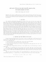
Figure
1.2
From
trunking
stations
to
VSATs
4
Introduction
the earth station. Indeed the user can directly plug into the
VSAT
equipment his
own communication terminals such as telephone or video set, personal computer,
printer, etc. Therefore
VSATs
appear as natural means to by-pass public network
operators by directly accessing satellite capacity. They are flexible tools for
establishing private networks, for instance between the different sites of a com-
pany-
Figure
1.2
illustrates this aspect by emphasising the positioning of
VSATs
near
the user compared to
trunking
stations, which are located at the top level of the
switching hierarchy of a switched public network.
The by-pass opportunity offered by
VSAT
networks has not always been well
accepted by national telecom operators as it could mean loss of revenues, as
a result of business traffic being diverted from the public network.
This
has
initiated conservative policies by national telecom operators opposed to the
deregulation of the communications sector. In some regions of the world, and
particularly in Europe, this has been a strong restraint to the development of
VSAT
networks.
1.2
VSAT NETWORK CONFIGURATIONS
As
illustrated in Figure 1.2,
VSATs
are connected by radio frequency links via
a satellite. Those links are radio frequency links, with a so-called 'uplink' from the
station to the satellite and a so-called 'downlink' from the satellite to the station
(Figure
1.3).
The overall link from station to station, sometimes called hop,
consists
of
an uplink and a downlink.
A
radio frequency link
is
a modulated
carrier conveying information. Basically the satellite receives the uplinked car-
riers from the transmitting earth stations within the field of view of its receiving
antenna, amplifies those carriers, translates their frequency to a lower band in
order to avoid possible output/input interference, and transmits the amplified
carriers to the stations located within the field of view of its transmitting antenna.
A
more detailed description of the satellite architecture is given in Chapter
2
(section 2.1).
satellite
n
Figure
1.3
Definition
of
uplink
and
downlink
VSAT
network
configurations
5
L
Figure
1.4
Geostationary satellite
Present
VSAT
networks use geostationary satellites, which are satellites orbit-
ing in the equatorial plane of the earth at an altitude above the earth surface of
35786
km.
It will be shown in Chapter
2
that the orbit period at
this
altitude is
equal to that of the rotation of the Earth.
As
the satellite moves on its circular orbit
in the same direction as the earth rotates, the satellite appears from any station on
the ground as a fixed relay in the sky. Figure
1.4
illustrates this geometry. It should
be noted that the distance from an earth station to the geostationary satellite
induces a radio frequency carrier power attenuation of typically
200
dB on both
uplink and downlink and a propagation delay from earth station to earth station
(hop delay) of about
0.25
S
(see Chapter
2).
As
a result of its apparent fixed position in the sky, the satellite can be used
24
hours a day as a permanent relay for the uplinked radio frequency carriers. Those
carriers are downlinked to all earth stations visible from the satellite (shaded area
on the earth in Figure
1.4).
Thanks to its apparent fixed position in the sky, there is
no need for tracking the satellite.
This
simplifies
VSAT
equipment and installa-
tion.
As
all
VSATs
are visible from the satellite, carriers can be relayed by the satellite
from any
VSAT
to any other
VSAT
in the network, as illustrated by Figure
1.5.
Regarding meshed
VSAT
networks, one must take into account the following
limitations:
-typically
200
dB carrier power attenuation on the uplink and the downlink as
a result of the distance to and from a geostationary satellite;
-limited satellite radio frequency power, typically a few tens of watts;
-small size of the
VSAT,
which limits its transmitted power and its receiving
sensitivity.
As
a result of the above, it may well be that the demodulated signals at the
receiving
VSAT
do not match the quality requested by the user terminals.
Therefore direct links from
VSAT
to
VSAT
may not be acceptable.
The solution then
is
to install in the network a station larger than a
VSAT,
called
the
hub.
The hub station has a larger antenna size than that of a
VSAT,
say
4
m to
6
Zntroduction
VSAT
VSAT
C
VSAT
B
4
VSAT
VSAT
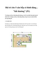
Figure
1.5
Meshed
VSAT
network. (a) Example with three
VSATs
(arrows represent
information flow as conveyed by the carriers relayed by the satellite).
(b)
Simplified
representation for a larger number
of
VSATs
(arrows represent bi-directional links made
of
two carriers travelling in opposite directions)
11
m, resulting in a higher gain than that
of
a
typical
VSAT
antenna, and is
equipped with a more powerful transmitter.
As
a
result
of
its improved capabil-
ity, the hub station is able to receive adequately all carriers transmitted by the
VSATs,
and to convey the desired information
to
all
VSATs
by means
of
its own
transmitted carriers. The architecture
of
the network becomes star shaped as
shown in Figures
1.6
and
1.7.
The
links
from the hub to the
VSAT
are named
'outbound links'. The ones from the
VSAT
to the hub are named 'inbound links'.
Both inbound and outbound links consist
of
two links, uplink and downlink, to
and from the satellite, as illustrated in Figure
1.3.
VSAT
network
configurations
/:
I
I
I
7
VSAT
A
VSAT VSAT
B
C
HUB
VSAT
VSAT
(b)
Figure
1.6
One-way star-shaped
VSAT
network.
(a)
Example
with
four
VSATs
(arrows
represent information flow
as
conveyed by the outbound carriers relayed by the satellite).
(b)
Simplified representation
for
a
larger number
of
VSATs
(arrows represent unidirec-
tionnal
links)
There are two alternatives to star shaped VSAT networks:
-One-way networks (Figure
1.6),
where
the
hub transmits carriers
to
receive-
only VSATs.
This
configuration supports broadcasting services from a central
site where the hub is located to remote sites where the receive-only VSATs are
installed.
-Two-way networks (Figure
1.7),
where VSATs can transmit
and
receive. Such
networks support interactive traffic.
8
lntroduction
VSAT
D
HUB
(b)
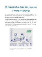
Figure
1.7
Two-way star shaped VSAT network. (a) Example with four VSATs (arrows
represent information flow as conveyed by the carriers relayed by the satellite).
(b)
Simplified representation for a larger number of VSATs (arrows represent bi-directional
links made of two carriers travelling
in
opposite directions)
The two-way connectivity between
VSATs
can be achieved
in
two ways:
-either direct links from
VSAT
to
VSAT
via satellite, should the link perform-
ance meet the requested quality (this is the mesh configuration illustrated in
Figure
1.5),
VSAT
network
applications and types
of
traffic
9
1
SATELLITE
1
Antenna
0.6-1.8m
Antenna
0.6-1.8171
Antenna
4-11111
Figure
1.8
VSAT
to
VSAT
connectivity
using
the hub as a relay
in
star shaped networks
-or by double hop links via satellite in a star shaped network, with a first hop
from VSAT to hub and then a second hop using the hub as a relay to the
destination VSAT (Figure
1.8).
In
conclusion, star shaped networks are imposed by power requirements
resulting from the reduced size and hence the low cost of the VSAT earth station
in
conjunction with power limitation
of
the satellite. Meshed networks are consider-
ed whenever such limitations do not hold, or are unacceptable. Meshed networks
have the advantage of a reduced propagation delay (single hop delay
is
0.25s
instead of
0.5s
for double hop) which is especially
of
interest for telephony
service.
1.3
VSAT NETWORK APPLICATIONS AND
TYPES
OF
TRAFFIC
VSAT networks have both civilian and military applications. These will now be
presented.
1.3.1
Civilian
VSAT
networks
1.3.1.1
Types
of
services
As mentioned
in
the previous section, VSAT networks can be configured as
one-way or two-way networks. Table
1.1
gives examples of services supported by
VSAT networks according to these two classes.
10
Introduction
Table
1.1
Examples of services supported by VSAT networks
One-way VSAT networks
Stock market and other news broadcasting
Training or continuing education at distance
Distribute financial trends and analyses
Introduce new products at geographically dispersed locations
Update market related data, news and catalogue prices
Distribute video or
TV
programmes
Distribute music in stores and public areas
Relay advertising to electronic signs in retail stores
Two-way VSAT networks
Interactive computer transactions
Low rate video conferencing
Database enquiries
Bank transactions, automatic teller machines
Reservation systems
Distributed remote process control and telemetry
Voice communications
Emergency services
Electronic funds transfer at point of sale
Medical data transfer
Sales monitoring and stock control
Satellite news gathering
It can be noticed that most of the services supported by two-way VSAT
networks deal with interactive data traffic, where the user terminals are most
often personal computers. The most notable exceptions are voice communications
and satellite news gathering.
Voice communications on a VSAT network means telephony with possibly
longer delays than that incurred on terrestrial lines as a result
of
the long satellite
path. Telephony services imply full connectivity, and delays are typically
0.25
S
or
0.50
S
depending on the selected network configuration, as mentioned above.
Satellite News Gathering
(SNG)
can be viewed as
a
temporary network using
transportable VSATs, sometimes called 'fly-away' stations, which are transported
by car or aircraft and set up at a location where news reporters transmit video
signals to a hub located near the company's studio. Of course the service could be
considered as inbound only, if it were not for the need to check the uplink from the
remote site, and to be in touch by telephone with the staff at the studio. As
'fly-away' VSATs are constantly transported, assembled and disassembled, they
must be robust, lightweight and easy to install. Today they weigh typically
250
kg
and can be installed in
20
minutes. Figure 1.9 shows
a
picture of a 'fly away' VSAT
station [ELI93].
VSAT
network applications and types
of
trafic
11
Figure
1.9
'Fly away'
VSAT
station. (Reproduced from
[EL1931
by permission of the
Institution
of
Electrical Engineers,
0
1993
IEE)
1.3.1.2
Types
of
traffic
Depending on the service the traffic flow between the hub and the
VSATs
may
have different characteristics and requirements.
Data transfer
or
broadcasting,
which belongs to the category of one-way services,
typically displays file traders of
1-100
Mkytes of data. This kind of service is not
delay sensitive, but requires
a
high integrity of the data which are transferred.
Examples of applications are computer download and distribution of data to
remote sites.
Interactive data
is
a
two-way service corresponding to several transactions per
minute and per terminal of single packets
50
to
250
bytes long on both inbound
and outbound links. The required response time is typically a few seconds.
Examples of applications are bank transactions, and electronic funds transfer at
point of sale.
12
VSAT
networks:
involved
parties
13
Enquiry/response
is
a two-way service corresponding to several transactions per
minute and terminal. Inbound packets (typically 30-100 bytes) are shorter than
outbound packets (typically
500-2000
bytes). The required response time
is
typically a few seconds. Examples of applications are airline or hotel reservations
and database enquiries.
Supervisory control and data acquisition
(SCADA)
is a two-way service corre-
sponding to one transaction per second or minute per terminal. Inbound packets
(typically
100
bytes) are longer than outbound packets (typically
10
bytes). The
required response time ranges from a few seconds to a few minutes. What is most
important is the high data security level, and the low power consumption of the
terminal. Examples of applications are control and monitoring of pipelines,
off-shore platforms, electric utilities and water resources.
Table
1.2
summarises the above discussion.
1.3.2
Military
VSAT
networks
VSAT networks have been adopted by many military forces in the world. Indeed
the inherent flexibility in the deployment of VSATs makes them a valuable means
to install temporary communications links between small units in the battlefield
and headquarters located near the hub [WEL93]. Moreover the topology of a star
shaped network fits well into the natural information flow between field units and
command base. Frequency bands are at X-band, with uplinks in the 7.9-8.4
GHz
band and downlinks in the 7.25-7.75
GHz
band.
The military user VSAT must be a small, low weight, low power station that
is
easy to operate under battlefield conditions. As an example, the manpack station
developed by the
UK
Defence Research Agency
(DRA)
for its Milpico VSAT
military network is equipped with a 45 cm antenna, weighs less than 17 kg and
can be set up within 90 seconds [WEL93]. It supports data and vocoded voice at
2.4 kb/s. In order to do
so,
the hub stations need to be equipped with antennas as
large as 14 m. Another key requirement is low probability of detection by hostile
interceptors. Spread spectrum techniques are largely used [EVA90, Chapter
151.
1.4
VSAT NETWORKS: INVOLVED PARTIES
The applications of VSAT networks identified in the previous section clearly
indicate that VSAT technology is appropriate to business or military applications.
Reasons are the inherent flexibility of VSAT technology,
as
mentioned above in
section
1.1,
cost savings and reliability, as will be discussed in section 3.3.
Which are the involved parties, as far as corporate communications are con-
cerned?
-The
user
is most often a company employee using office communication
terminals
such as personal computers, telephone sets, and fax machines.
On
14
Introduction
other occasions the terminal
is
transportable, as with satellite news gathering
(SNG).
Here the user is mostly interested in transmitting video to the company
studio. The terminal may be fixed but not located in
an
office as with
SCADA
(supervisory control and data acquisition) applications.
-The
VSAT
network operator
may be the user’s company itself, if the company
owns the network, or it may be a telecom company (in many countries it
is
the
national public telecom operator) who then leases the service. The
VSAT
network operator is then a customer to the network and/or the equipment
provider.
m
Figure
1.10
VSAT
networks: involved parties
VSAT
network
options
15
-The VSAT
network provider
has the technical ability to dimension and install the
network.
It
elaborates the network management system (NMS) and designs the
corresponding software. Its inputs are the customer's needs, and its customers
are network operators. The network provider may be a private company or
a national telecom operator.
-The
equipment provider
sells the VSATs and/or the hub which it manufactures.
It may be the network provider or a different party.
For the VSAT network to work, some
satellite capacity
must be provided. The
satellite may be owned by the user's company but
this
is a rare example of
'vertical integration', and most often the satellite is operated by a different party.
This party'may be a private satellite operator, a national satellite operator, or an
international organisation such as INTELSAT or EUTELSAT. In the latter case,
and up till now, only a signatory to the organisation is allowed to lease satellite
capacity and to provide it secondhand. Most often the signatory is a national
telecom operator.
The above parties are those involved in the contractual matters. Other parties
are on the regulatory side and their involvement will be first presented in section
1.9
and developed with more details in Chapter
3.
Figure
1.10
summarises the above discussion. The terminology will be used
throughout the book, and therefore Figure
1.10
can serve as a convenient
reference.
1.5
VSAT
NETWORK
OPTIONS
1.5.1
Star
or
mesh?
Section
1.2
introduced the two main architectures of a VSAT network: star or
mesh. The question now is: is one architecture more appropriate than the other?
The answer depends on three factors:
-the structure of information flow within the network;
-the requested link quality and capacity;
-the transmission delay.
These three aspects will now be discussed.
1.5.1
.l
Structure
of
information
flow
VSAT networks
can
support different types of applications, and each has
an
optimum network configuration:
16
Introduction
Table
1.3
VSAT
network
configuration
appropriate
to
a
specific application
Application
Network configuration
Star shaped Star shaped Meshed
one-way
two-way
two-way
Broadcasting
Corporate network (hub
at
company headquarters,
VSATs
at
branches)
Corporate network
(distributed
sites)
X
X
X
X
(double hop) (single hop)
-Broadcasting: a central site distributes information to many remote sites with
no back flow of information. Hence a star shaped one-way network supports
the service at the lowest cost.
-Corporate network: most often companies have a centralised structure with
administration and management performed at a central site, and manufactur-
ing or sales performed at sites scattered over a geographical area. Information
from the remote sites needs to be gathered at the central site for decision
making, and information from the central site has to be distributed to the
remote ones, such as task sharing. Such an information flow can be partially
supported by a star shaped one-way
VSAT
network, for instance for informa-
tion distribution, or totally supported by a two-way star shaped
VSAT
net-
work. In the first case,
VSATs
need to be receive-only and are less expensive
than in the latter case where interactivity is required, as this implies
VSATs
equipped with both transmit and receive equipments. Typically the cost of the
transmitting equipment is two-thirds that of an interactive
VSAT.
-interactivity between distributed sites: other companies or organisations with
a decentralised structure are more likely to comprise many sites interacting one
with another.
A
meshed
VSAT
network using direct single hop connections
from
VSAT
to
VSAT
is hence mostly desirable. The other option is a two-way
star shaped network with double hop connections from
VSAT
to
VSAT
via the
hub.
Table
1.3
summarises the above discussion. Regulatory aspects also have to be
taken into account (see Chapter
3).
1.5.1.2
Link quality and capacity
The link considered here is the link from the transmitting station to the receiving
one. Such a link may comprise several parts: for instance a single hop link would
VSAT
network
options
17
satellite
user terminal
BASEBAND
LINK
user terminal
Figure
1.11
Overall radio frequency
(W)
link and user-to-user baseband link
comprise an uplink and a downlink (Figure
1.3),
a double hop link would
comprise two single hop links, one being inbound and the other outbound (Figure
1.8).
When dealing with link quality, one must refer to the quality of
a
given signal.
Actually two types of signals are involved: the modulated carrier at the input to
the receiver and the baseband signals delivered to the user terminal once the
carrier has been demodulated (Figure
1.11).
The input to the receiver terminates
the
overall radio frequency link
from the transmitting station to the receiving one,
with its two link components, the uplink and the downlink. The earth station
interface to the user terminal terminates the
user-to-user baseband link
from the
output of the device generating bits (message source) to the input of the device to
which those bits are transmitted (message sink).
The link quality of the radio frequency link is measured by the
(C/N,),
ratio at
the station receiver input, where
C
is the received carrier power and
No
the power
spectral density of noise
[MAR93,
Chapter
21.
The baseband link quality is measured by the information bit error rate
(BER).
It
is conditioned by the
E,/&
value at the receiver input, where
E,
(J)
is the energy
per information bit and
No
(W/Hz)
is the noise power spectral density.
As
indicated in Chapter
5,
section
5.7,
the Eb/No ratio depends on the overall radio
frequency link quality
(Cmo),
and the capacity of the link, measured by its
information bit rate
R,
(b/s):
Figure
1.12
indicates the general trend which relates EIRP to
G/”
in a
VSAT
network, considering a given baseband signal quality in terms of constant
BER.
EIRP designates the effective isotropic radiated power of the transmitting
Zntroduction
41
l
outbound link
inbound link
,AT
CUNe
2
CUNe
1
double
hop
single
hop
(G~SAT
(WHUB
Figure
1.12
EIRP
versus
G/T
in a VSATnetwork. Curve
1:
single hop from VSAT to VSAT
in
a meshed network. Curve 2: double hop from VSAT
to
VSAT via
the
hub
equipment and
G/T
is the figure of merit of the receiving equipment (see Chapter
5,
for definition of the EIRP and of the figure of merit).
As can be viewed from Figure
1.12,
the double hop from VSAT to VSAT via the
hub, when compared to a single hop, allows an increased link capacity, without
modifying the size of the VSATs. Now this option also involves a larger trans-
mission delay.
1.5.1.3
Transmission delay
With a single hop link from VSAT to VSAT
in
a meshed network, the propagation
delay is about
0.25s.
With a double hop from VSAT to VSAT via the hub, the
propagation delay is twice as much, i.e. about
0.5
S.
Double hop may be a problem for voice communications. However, it is not
a severe problem for video or data transmission.
Table
1.4
summarises the above discussion: given the EIRP and
G/r
values for
a VSAT, the designer can decide for either a large delay from VSAT to VSAT and
Table
1.4
Characteristics of star and mesh network configuration.
Network
configuration
Star
shaped Mesh
(double hop) (single hop)
Capacity large
Delay 0.5
S
(given VSAT
EIRP
and
CD')
(from
VSAT
to
VSAT)
small
0.25
S
VSAT
network
options
19
a larger capacity or a small delay and a lower capacity, by implementing either
a star network, or a mesh one.
1.5.2
Datdvoicehideo
Depending on his needs, the customer may want to transmit either one kind of
signal, or a mix of different signals. Data and voice are transmitted in a digital
format, while video may be analogue or digital. When digital, the video signal
may benefit from bandwidth efficient compression techniques.
1.5.2.1 Data transmission
VSATs have emerged from the need to transmit data. Standard VSAT products
offer data transmission facilities. Rates offered to the user range typically from
50
b/s to
64
kb/s with interface ports such as E-232, V24 and
V28
for bit rates lower
than
20
kb/s, and Rs-422, RS-449,
V11,
V35 and X21 for higher bit rates. Appendix
3 gives some details on the functions of such ports.
Data distribution can be implemented in combination with video transmission
using the Multiplexed Analogue Components (MAC) standard (see below: Video
transmission), MAC also allows data transmission only (data occupy the full
video frame and then no video is transmitted). Capacity then is as high as
20
Mb/s.
1.5.2.2 Voice transmission
Voice communications are
of
interest on two-way networks only. They can be
performed at low rate using voice encoding (vocoder). Typical information rate
then ranges from 4.8kb/s to 9.6kb/s. They can also be combined with data
transmission (for instance up to four voice channels may be multiplexed with data
or facsimile channels on a single 64 kb/s channel).
On
VSAT networks voice
communications suffer from delay associated with vocoder processing (about
50ms) and propagation on satellite links (about 500 ms for a double hop).
Therefore the user may prefer to connect to terrestrial networks which offer
a reduced delay. Voice communications can be a niche market for VSATs as
a service to locations where land lines are not available, or for transportable
terminal applications.
1.5.2.3 Video transmission
On
the outbound link (from hub to VSAT), video transmission makes use of usual
TV
standards
(NTSC,
PAL or SECAM)
in
combination with
FM
modulation,
or
20
Introduction
can be implemented on Multiplexed Analogue Components
(MAC)
standards
(B
MAC or
D2
MAC), possibly in combination with distribution of data.
On
the inbound link, as a result of the limited power of the VSAT on the uplink,
video transmission is feasible at a low rate, possibly in the form of slow motion
image transmission using video coding and compression.
1.5.3
Fixed/demand assignment
The earth stations of a VSAT network communicate via the satellite by means of
modulated carriers. Any such carrier is assigned a portion
of
the resource offered
by the satellite in terms of powered bandwidth.
This
assignment can be defined
once for all, and this is called ‘fixed assignment’ (FA), or in accordance with
requests from the VSATs depending on the traffic they have to transmit, and this is
called ’demand assignment’ (DA).
1.5.3.1
Fixed
assignment
(FA)
Figure
1.13
illustrates the principle
of
fixed
assignment.
A
star shaped network
configuration is considered in the figure but the principle applies to a meshed
network configuration as well. The satellite resource
is
shared in a fixed
manner by all stations whatever the traffic demand. It may be that at a given
instant the VSAT traffic load is larger than that which can be accommodated by
capacity allocated to that VSAT as determined by its share of the satellite resource.
The VSAT must store or reject the traffic demand, and this either increases the
delay, or introduces blocking of calls, in spite of the fact that other VSATs may
have excess capacity available. Because
of
this, the network is not optimally
exploited.
U
Figure
1.13
Principle
of
fixed
assignment
VSAT
network
options
21
1.5.3.2
Demand assignment (DA)
With
demand assignment,
VSATs
share a variable portion of the overall satellite
resource as illustrated in Figure
1.14.
VSATs
use only the capacity which is
required for their own transmission, and leave the capacity
in
excess for use by
other
VSATs.
Of course this variable share can be exercised only within the limits
of the total satellite capacity allocated to the network.
Demand assignment is performed by means of requests for capacity transmit-
ted by individual
VSATs.
Those requests are transmitted to the hub station, or to
a traffic control station, should the management of the demand assignment
technique be centralised, or to all other
VSATs,
if the demand assignment is
distributed. Those requests are transmitted on a specific signalling channel, or
piggy-backed on the traffic messages. With centralised management, the hub
station or the trafficcontrol station replies by allocating to the
VSAT
the appropri-
ate resource, either a frequency band or a time slot. With distributed manage-
ment, all
VSATs
keep a record of occupied and available resource. This is
discussed in more detail in Chapter
4,
section
4.6.
From the above, it can be recognised that demand assignment offers a better use
of the satellite resource but at the expense of a higher system cost and a delay in
connection set-up. However, a larger number of stations can share the satellite
resource. Hence the higher investment cost is compensated for by a larger return
on investment.
The centralised/distributed management option depends on the network
architecture: a centralised control is easier to perform with a star shaped network,
as all traffic
flows
through the hub, which then is the natural candidate for
demand assignment control. With a mesh shaped network, both centralised and
distributed control can be envisaged. Delay for link set-up is shorter with
distributed control, as a single hop (about
0.25
S)
is sufficient to inform all
VSATs
in
the network of the request and the corresponding resource occupancy, while
a double hop (about
0.5
S)
is necessary for the request to proceed to the central
station, and for that station to allocate the corresponding resource. Finally, as
variable
1
share
C
(TX)
dnmnn
large
tr
Figure
1.14
Principle
of
demand assignment
22
Introduction
demand assignment implies charging the remote sites according to the resource
occupancy, billing and accounting is more easily handled by a centralised control.
1.5.4
C-band
or
Ku-band?
VSAT networks are supposed to operate within the so-called ‘fixed satellite
service’
(FSS)
defined within the International Telecommunication Union
(ITU).
m
primary and exclusive albcatiin
Rt
:
Region
1
(Europe, Africa, and
CS)
A\\
primary and shared allocation
uplink downlink
R2
:
Region
2
(the Americas)
WW
:
world wide
R3
:
Region
3
(India, Asia, Australia, Pacific)
t
C-band
rrl
ww
ww
GHz
3.4
GHz
4.2
GHz
4.5
GHz
4.0
c
p
R1
ww
5.725
5.850
GHz
GHz
7.075
GHz
Ku-band
GHz
10.7
R1
ww
GHz
12.5 12.75
GHz
13.25
GHz
GHz
11.7
GHz
GHz
12.1 12.2
GHz GHz GHz
12.5 12.7 12.75
ww
m;;
ww
13.75
GHz
GHz GHz
GHz
14.3 14.4 14.5
Ka-band
GHz
17.7
19.7 20.1
GHz
GHz
27
GHz GHz
27.5
29.5 29.9
GHz
GHz
Figure
1.15
Frequency bands allocated to the Fixed Satellite Service
(FSS)
and
usable
for
VSAT
networks
[ITu90]
VSAT
network
options
23
The only exception is when data are broadcast in association with broadcasting of
television or audio programmes, within the so-called 'broadcasting satellite
service'
(BSS).
The FSS covers all satellite communications between stations located while
operating at given 'specified fixed points' of the Earth. Transportable stations
belong to
this
category, and hence the so-called 'fly-away' stations should use the
same frequency bands as fixed VSATs.
The most commonly used bands for commercial applications are those allo-
cated to the FSS at C-band and Ku-band, as indicated in Figure 1.15.
The figure displays uplinks and downlinks by means
of
arrows oriented
upward or downward. The black arrows indicate a primary and exclusive
allocation for
FSS,
which means in short that the FSS is protected against
interference from any other service, which is then considered as secondary. The
striped arrows indicate a primary but shared allocation, which means that the
allocated frequency bands can also be used by services other than FSS with
the same rights. Coordination
is
then mandatory, according to the procedure
described in the
ITU
Radio Regulations.
The
FSS
also has bands allocated at X-band (about
8
GHz uplink and
7
GHz
downlink) and Ka-band (about 14 GHz uplink and 12 GHz downlink). X-band is
occupied by military systems and Ka-band
is
at present used by experimental
systems only.
As mentioned above, data may be carried in association with video signals
within the frequency band allocated to the broadcasting satellite service. Possible
bands are 11.7-12.5 GHz in regions
1
and
3,
and 12.2-12.7 GHz in region 2, filling
in the gaps
of
the bands represented in Figure 1.15 which deals with the fixed
satellite service only.
The selection of a frequency band for operating a VSAT network depends first
on the availability of satellites covering the region where the VSAT network is to
be installed. C-band satellites are available in most regions of the world (actually
only the high latitudes above about
70"
are not covered) while Ku-band satellites
are available mainly over North America, Europe, East Asia and Australia. Figure
1.16 gives a general picture
of
the regions of the world where C-band or Ku-band
satellite coverage is available.
To be considered next
is
the potential problem of interference.
Interference designates unwanted carriers entering in the receiving equipment
along with the wanted ones. The unwanted carriers perturb the demodulator by
acting as noise adding to the natural thermal noise. Interference
is
a problem with
VSATs because the small size of the antenna (small aperture) translates into
a radiation pattern with a large beamwidth. Indeed as shown by equation (1.2) the
half power beamwidth
&dB
of an antenna relates to the product of its diameter by
frequency (see Appendix 4), as follows:
=
70
-
(degrees)
C
Df
where
D(m)
is the diameter of the antenna, f(Hz)
is
the frequency, and
c
=
3
X
10' m/s is the velocity of light.
24
Introduction
Figure
1.16
Regions
of
the
earth where
C-band
and
Ku-band
satellite
coverage
is
available
Therefore, the smaller the antenna diameter, the larger the beamwidth, and the
off-axis interfering carriers are more likely to be emitted or received with high
antenna gain. How important this perturbation can be is discussed in Chapter 5,
section 5.5.
At this point it suffices to mention that interference is more likely to be
a problem at C-band than at higher frequencies. There are
two
reasons: first, there
is no primary and exclusive allocation to FSS at C-band. Second, given the earth
station antenna diameter, interference is more important at C-band than at
Ku-band, as the beamwidth is inversely proportional to the frequency, and thus is
larger at C-band than at higher frequencies. To put this in perspective, formula
(1.2)
indicates for a
1.8
m antenna a beamwidth angle of
3"
at
4
GHz, and only
1"
at
12
GHz. This means that the receiving antenna is more likely to pick up carriers
downlinked from satellites adjacent to the wanted one at C-band than at Ku-band,
especially as C-band satellites are many and hence nearer each other.
A
typical
angular separation for C-band satellites is
3",
and is therefore comparable to
VSAT antenna beamwidth.
The same problem occurs on the uplink where a small VSAT antenna projects
carrier power in a larger angle at C-band than at Ku-band, and hence generates
more interference on the uplink of adjacent satellite systems. However this is not
a major issue as the transmit power of VSATs is weak.
Finally it should be known that C-band and parts of Ku-band are shared by
terrestrial microwave relays, and this may be another source of interference.
Ku-band offers dedicated bands free from any terrestrial microwave transmission
(see black arrows in Figure 1.15), which is not the case for C-band. This simplifies
the positioning of the VSAT and hub station as no coordination is implied.
Figure 1.17 summarises the various interfering paths mentioned above.
Where the small size of the antenna is at a premium, and should interference be
too large, interference can be combated by using a modulation technique named
VSAT
network
options
25
transmitting
earthstation
earth
station
earth
Sation
system
1
earth
statkm
IeCeMng
transmirting
recehmg
system1
system2
system
2
spread
spectrum
which consists in spreading the carrier in a much larger
bandwidth than strictly required to transmit the information.
This
is an inter-
esting technique as it provides not only interference protection but also po-
tential for code division multiple access (CDMA) to a satellite channel, as will
be shown in Chapter
4,
section
4.6.
However, as a result
of
the higher utilised
bandwidth, it is less bandwidth efficient compared to alternative multiple
access techniques such as Frequency Division Multiple Access (FDMA) or Time
Division Multiple Access (TDMA), which can be used where interference is not
too severe.
Finally, the cost of the equipment is another driving factor for selecting between
C-band and Ku-band. Although C-band technology is cheaper, the larger size
of
the VSAT antenna for a similar performance makes the VSAT more expensive
than at Ku-band.
Table
1.5
summarises the advantages and drawbacks of the most commonly
available frequency bands.