Foundation Flash CS4 for Designers- P6 ppt
Bạn đang xem bản rút gọn của tài liệu. Xem và tải ngay bản đầy đủ của tài liệu tại đây (1.56 MB, 30 trang )
132
CHAPTER 3
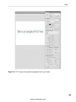
2. Select the Frame movieclip in the library and enable
9- slice scaling. Open the movieclip in the
Symbol Editor
and adjust the guides to match those shown in Figure 3-9.
Note that the top guide, in area 1, is positioned low
enough to encompass the full extent of the feather.
3. Click the Scene 1 link to return to the main timeline.
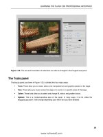
4. Select the Free Transform tool and adjust the picture
frames to fit the image, as shown in Figure 3-10. Even
though each photo has its own width, the same symbol
can now be used to neatly frame these different dimen-
sions.
5. Save and close the file.
Figure 3-10. 9- Slice scaling allows Peter Pan to fly.
9-slice “gotchas”
In the first edition of this book, Foundation Flash CS3 for Designers, we discovered a number of 9- slice
“gotchas” that took us by surprise. Most of these have disappeared in Flash CS4, even when publish-
ing to previous versions of Flash Player (keeping in mind that Flash Player 8 is the minimum version
to support 9- slide scaling). Some of these issues included the use of rotated graphic symbols in the
corners—simply not workable at the time—as well as batty behavior when a 9- slice symbol was edited
Figure 3-9. Applying 9- slice scaling
and adjusting the guides
133
SYMBOLS AND LIBRARIES
in place, but pixie dust seems to have truly come to the rescue. 9- slice scaling is a lot more stable in
Flash CS4 than it used to be. That said, there are still a few issues you should know about.
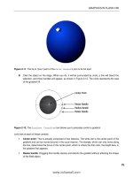
The first issue concerns the area in the middle of the 9- slice grid, which scales across both the hori-
zontal and the vertical axes. If you have content in the center area of the grid (area 5), such as a gradi-
ent or image, it will distort if the scaling is uneven. Take a look for yourself. Open the 5Ohe_a.*osb file
and click the frame to drag out a corner (this is an interactive SWF). Notice how the flower distorts,
as shown in Figure 3-11. This happens because the frame and the flower are both in the area 5 slice.
Depending on your needs, this makes 9- slice symbols useful only as background borders, layered
behind content that simply must not be distorted. In the LapanL]j*bh] file, the photos are on layers
of their own.
Figure 3-11. The center area of a symbol containing 9- slice scaling scales
on two axes. The area in the middle will distort.
Another issue involves maintaining the integrity of any drawings or objects used in the corners. Shapes,
drawing objects, primitives, graphic symbols, and even imported bitmaps can be used. Movieclips can’t
be used. You can see what we’re talking about in Figures 3- 12 and 3- 13. We started with nothing
more than a rounded rectangle with a square in the upper left. The square is represented by a shape,
a drawing object, a primitive, a graphic symbol, a movieclip symbol, and an imported TIFF file.
When the objects are stretched along the horizontal axis using the
Free Transform tool, the object in
the upper- left corner is fine in all versions except the movieclip, which is distorted (see Figure 3-13).
Figure 3-12. We start with a simple object. Figure 3-13. Note the distortion in the bottom two examples.
134
CHAPTER 3
It’s OK to rotate symbols that are not movieclips in 9- slice corners, but they
look right only when your FLA is configured for ActionScript 3.0.
Finally, masking layers inside a 9- slice movieclip will deci-
sively pummel that symbol and kick it to the curb. Masking
just can’t be combined with this feature, as cool as it would
be. Consider the example of a wooden frame, where the
intent is to use an actual snapshot of a distressed piece of
wood—an imported bitmap—with 9- slice scaling to create
a wooden frame that can fit any photograph. In Figure 3-14,
an imported JPG is used as a bitmap fill for four rectangles.
To angle the corners, masks are applied to the layers named
top and bottom.
What’s the result? Take a look at Skk`Bn]iaI]oga`*bh] in
the Chapter 3 Atan_eoa folder, and you’ll see the problem
right away. The rectangles simply don’t resize according
to the rules of 9- slice scaling. Fortunately, those angled
corners can be made without masking layers. Look at
Skk`Bn]ia*bh], and you’ll see that the
Subselection tool
was used to bring in the actual corner anchor points directly
( Figure 3-15). The result—without the masking—succeeds,
as shown in Figure 3-16.
Figure 3-15. Rearranging anchor points gets rid of the masking issue.
Figure 3-14. Masking will break
9- slice scaling.
135
SYMBOLS AND LIBRARIES
Figure 3-16. A resizable wood frame using 9- slice scaling and a single JPG for the wood
The bottom line is that you should use 9- slice scaling with care. The idea is a good one, but don’t go
nuts with it. Keep it simple! Avoid nesting symbols too deeply in the corners and sides. If you insist on
using bitmaps, bear in mind that they will sometimes stretch in ways that may not be predictable. We
encourage you to experiment on your own, but by all accounts, the simpler, the better.
Sharing assets
One of the really useful features of library assets—symbols or otherwise—is that they can be made
available to FLAs other than the current movie. Assets in a Flash library can be shared with other Flash
movies in two ways: author- time shared libraries and runtime shared libraries. This is extremely helpful
if you are working on a stockpile of movies and need to use the same assets across numerous Flash
documents. Here’s a quick look at the difference between the two.
Author-time shared libraries
The term author- time refers to production time—the time during which you, the designer (author),
actually build your content. Author- time shared libraries, therefore, refer to assets shared among
FLA files that haven’t yet been converted to SWFs. Animators make extensive use of this feature. An
animator will, for example, create a character composed of a number of symbols—eyes, arms, legs,
and hands, for instance—that are used to put the character in motion. As the animations are built
in a series of movies, the animator will use symbols that were created in a centralized (and separate)
136
CHAPTER 3
character library instead of redrawing them. If a change happens in the centralized author- time shared
library, the edit ripples across to all the FLAs that borrow from it. Here’s how to use symbols from
another FLA:
1. Create a new Flash document and open the new document’s library. As you can see, it is empty.
2. Select File ° Import ° Open External Library, or press Ctrl+Shift+O (Cmd+Shift+O), as shown in
Figure 3-17.
Figure 3-17. Importing a library from one Flash document
into another
3. In the Open dialog box, navigate to the Chapter 3 Atan_eoa folder and open
IkkjKranH]gaJ]j]ckkg*bh].
4. The library for the selected movie will open, but there are a couple of things missing from that
library: the drop- down menu, the pushpin, and the
Open New Library button. In addition, the
Library panel itself looks grayed out. All of these are visual clues that the IkkjKranH]gaJ]j]ckkg*
bh] file itself isn’t open—only its library is.
5. Drag the Trees symbol from the shared library to the empty library. When you release the
mouse, the symbol will appear in the empty library and become available for use in that movie
(see Figure 3-18).
Figure 3-18. Drag a symbol from the imported library to the empty library.
137
SYMBOLS AND LIBRARIES
6. Right-click (Ctrl- click) the Trees symbol you just dragged to the empty library and select
Properties. Take a look at the Source area of the Symbol Properties dialog box ( Figure 3-19).
Next to the Browse button, it tells you the original FLA of the shared symbol. Clicking the
Browse button lets you “unhook” the association from one FLA to another.
The Symbol button gives you the same concept, but for symbols, once the origination FLA
is chosen.
The Always update before publishing check box is important. It ensures that the current
movie, when you publish it, runs through all its associated external FLAs to see if any of
their shared assets have been updated. If so, it updates the current movie’s version of them
before publishing.
Figure 3-19. The Source area of the Symbol Properties
dialog box manages shared assets.
7. Close the file without saving the changes.
You can share any library item between movies as described in the previous steps. That includes fonts,
audio files, and bitmaps, not just symbols.
Runtime shared libraries
The concept of author- time shared libraries is useful enough, but it gets better. Since the introduc-
tion of Flash 5, Flash designers and developers have had the ability to extend this “interlibrary loan”
process to published SWFs, which means the benefits extend past author- time into . . . runtime. Why
would you want to create a runtime shared library? Because such a library needs to be downloaded
only once, even if several other SWFs access its symbols. To continue with the animator example, you
might be creating a character animation that uses the same large background image in ten separate
movies. Rather than adding the image to all ten FLAs—not a good idea, because its file size will be
added to each final SWF, even with an author- time shared library—you can have that symbol reside
in a runtime shared library on the web server. This way, the library SWF is loaded only once, but used
by several movies.
The key to runtime sharing is something called a linkage class. Select an item in the library, right- click
(Ctrl- click), and select
Properties. In the Symbol Properties dialog box, you will see a Linkage area
(shown in Figure 3-20). If an asset is to be shared at runtime, you must select
Export for runtime sharing,
and then enter the location of the intended shared library SWF. In the example in Figure 3-20, the
URL
field indicates that the SWF will be named Od]na`He^n]nu*osb and will be located in the same folder
as the other SWFs that use it. If the shared library were in a different location, you would enter a full
path, such as dppl6++sss*IuAt_ahhajpOepa*_ki+Od]na`He^n]nu*osb.
138
CHAPTER 3
Clicking
Export for runtime sharing automatically selects the Export
for ActionScript
check box, which in turn enables the Class field.
This linkage class provides ActionScript with a unique label for
this particular asset. (The field fills automatically, but you can
change the class name, if you like.) Does the usage of runtime
shared libraries require ActionScript? Oddly, not necessarily. But
runtime sharing doesn’t work without the linkage class.
Runtime sharing is possible for any asset that supports a linkage
class, which includes quite a few assets: fonts, audio files, mov-
ieclips, and bitmaps, but not graphic symbols. Items in shared
libraries can also be created when a symbol is first created (see
Figure 3-21). This works because the
Create New Symbol dialog
box is essentially the same as the
Symbol Properties dialog box.
Figure 3-21. Symbols can be added to shared libraries
when they are created.
Using a runtime shared library requires, of course, that the shared library be published as a SWF—the
file named in the
URL field of the Symbol Properties dialog box—and that this SWF be uploaded to the
server along with your actual movie SWFs.
To include an asset from a runtime shared library, follow the same steps listed in the previous section
for author- time shared libraries. Just open the shared library as an external library and drag over any
Figure 3-20. Adding items to a shared library
using the Symbol Properties dialog box
139
SYMBOLS AND LIBRARIES
assets that can be given a linkage class. The difference is that runtime assets don’t contribute to the
borrowing SWF’s file size, even though they appear as library items in the receiving FLA.
Updating shared assets
Obviously, things will rarely remain the same in your workflow. Things change and, more often than
not, these changes ripple through a number of movies. As an example, let’s assume that you need
to add or remove something from the background image used in your runtime shared library. This is
quite easily accomplished:
1. Open the originating FLA that contains the image and make your revisions in the Symbol Editor.
When you finish, save and publish the document, and close the FLA.
2. Open a Flash document that uses the shared asset and open its library.
3. Select the symbol that was changed, and select Update from the library’s drop- down menu
or, alternatively, right- click (Ctrl- click) on the desired item and select
Update from the context
menu. This will open the
Update Library Items dialog box (shown in Figure 13-22).
Figure 3-22. Symbols that have changed in a shared library can
quickly be updated wherever they are used.
4. In the Update Library Items dialog box, select the check box next to the item’s name, and then
click the
Update button.
As mentioned earlier, you can also use the
Symbol Properties dialog box to configure shared items to
update automatically.
If you have been carefully going through the chapter to this point, you are probably thinking, “Man,
there is a lot of serious stuff that I have to know!” We don’t deny that, but once you understand the
serious stuff, you can then start having fun with symbols. In fact, let’s start.
A word from the bunnies
Jennifer Shiman has created what is arguably one of the funniest sites on the Web (dppl6++sss*
]jcnu]heaj*_ki+). On a regular basis, she releases a Flash movie that uses the following premise: the
movie is a 30- second synopsis of a popular film and the actors are bunnies. Drawing and animating
each bunny would be a daunting task. Jennifer’s solution is the use of a shared library containing all
of the “bunny bits” needed to create the animations (see Figure 3-23). This is what Jennifer says about
how she does it:
140
CHAPTER 3
Figure 3-23. Shared libraries help Jennifer manage
complex animations.
This is my library of “bunny bits,” which I incorporate into each of my 30- Second Bunnies Theatre
cartoons. I’ve compiled a bunch of the symbols I use most commonly in animating the bunnies, and
I grouped them into folders. For instance, within the “bun mouths” folder are subfolders of different
mouth shapes for lip sync; mouths smiling and frowning; mouths in color and black and white;
mouths of differing line thickness. The “bkgds” folder contains background symbols I frequently
use, such as standardized clouds, grass, and trees. At the beginning of production, I’ll open the
bunny bits Library and drag the folders into the Library of my current cartoon file. Then I import the
additional artwork specifically pertaining to that cartoon.
During the course of production, if I create new bunny- related artwork I want to use in future
files (such as a new version of a bunny mouth shape or a bunny arm position I’ll use often), I drag
those symbols into the bunny bits Library file. It saves time to have one central location for these
types of reusable elements.
141
SYMBOLS AND LIBRARIES
Filters and blend modes
The introduction of filters and blend modes in Flash 8 was a direct response to Flash designers asking
for more eye candy. These features are just as fulfilling in Flash CS4.
Applying filters
For years, designers have been quite comfortable using Photoshop filters or Fireworks Live Effects.
Back in the old days, if an asset with blurs, drop shadows, and glows needed to appear in Flash, it
meant leaving Flash and opening an imaging application where such filters could be applied, then
exporting as a PNG file and importing that bitmap image into Flash. If the asset needed revision,
boom—you had to make the round- trip again. Thankfully, these same filters have become a part of
Flash. The ability to use filters directly gives you a quick-and- easy method to create some fascinating
visual effects.
The following filters are available in Flash:
Drop Shadow: Places a gray or colored shadow beneath an object, which gives it the appear-
ance of floating over the background.
Blur: Takes the subject out of focus, making it look smudged or out of the depth of field.
Glow: Creates a faint colored outline that glows around an object by following its curves.
Bevel: Gives an object a 3D look by creating shadows and highlights on opposite edges.
Gradient Glow: Nearly the same as the Glow filter, except that the glow follows a gradient of
colors from the inside to the outside edges of the object.
Gradient Bevel: Comparable to the Bevel filter, except that a gradient is applied to the shadow
and the highlights of the bevel.
Adjust Color: Allows you to adjust the brightness, contrast, hue, and saturation of an object.
There are also three filters that can be applied only through the use of ActionScript:
Color Matrix, Displacement Map, and Convolution. Check out the ActionScript 3.0
Language and Components Reference for explanations and demonstrations of how
to use these filters. Look for the ?khknI]pnetBehpan, @eolh]_aiajpI]lBehpan, and
?kjrkhqpekjBehpan classes. See Chapter 4 for details on using the ActionScript 3.0
Language and Components Reference.
A filter can’t be applied to everything. Filters can be applied only to movieclips, buttons, or text. This
makes sense, as far as importing goes, because the bulk of the movieclips that receive filters will either
arrive in Flash as exports from Photoshop or Fireworks or as line art from Illustrator. When you import
these assets into Flash, you will most likely import them as movieclip symbols. If an imported image
has transparent areas, the filter—such as a drop shadow—is applied only to the opaque edges of the
symbol that contains the image.
142
CHAPTER 3
Applying a Drop Shadow filter
In Flash, you can apply filters using a couple of methods. The most common is to select the object on
the stage and then twirl down the
Filters twirlie on the Property inspector. Filters can also be applied
through ActionScript.
As an example, let’s see how to get creative with the Drop Shadow filter:
1. Open the Behpan*bh] file in the Chapter 3 Atan_eoa folder. You will see that a cartoon of one
of the authors has been placed over an image of something going on in a street in Paris (see
Figure 3-24). The cartoon is a Photoshop image that was imported into the library as a movieclip.
Figure 3-24. We start with a Photoshop image imported into Flash.
The authors would like to thank Chris Flick of Community MX and CSFGraphics
$dppl6++sss*_ob)cn]lde_o*^hkcolkp*_km/) for allowing us to use this cari-
cature of Tom. Chris is a colleague at Community MX, where he produces the
weekly strip CMX Suite every Tuesday at dppl6++sss*_kiiqjepuit*_ki+.
2. Select the character on the stage and turn your attention to the Filters area in the Property
inspector
.
3. Click the Add Filter button in the bottom left to open the drop- down menu. Select Drop Shadow.
The
Property inspector will change to show the various options for this filter and the selection
on the stage will also develop a drop shadow using the current default values for the Drop
Shadow filter.
4. Change the Blur X and Blur Y values to 8 to make the shadow a little bigger. Also change the
Quality setting to High and the Distance value to 10. The shadow should now look a lot better
(see Figure 3-25).
143
SYMBOLS AND LIBRARIES
Figure 3-25. The filter is applied to the selection.
The lock joining the Blur X and Blur Y values ensures that the two values remain equal. Click the lock if
you want the
Blur X and Blur Y values to be different.
The first rule of “Flash physics” states, “For every action, there is an equally opposite and ugly implica-
tion.” Selecting
High quality results in a great- looking shadow. The ugly implication is that this setting
requires more processing power to apply. This is not a terrible thing if the image is static. For objects
in motion, however, keep the setting at
Low.
Our result is not bad, but we can do a lot better than that. The problem is the real- life shadows in the
photo. Notice how they are at a different angle from the one used for the character? Let’s fix that.
Adding perspective
We are going to make this effect look a little more realistic. Applying the Drop Shadow filter in the
previous steps resulted in a character that looks flat. In this exercise, you are going to add perspective.
Follow these steps:
1. Select the object on the stage and click the Trash Can icon at the bottom of the Property
inspector
to remove the Drop Shadow filter. With the object selected on the stage, copy it to
the clipboard.
2. Add a new layer, give it a name, and with the new layer selected, select Edit ° Paste in Place.
A copy of the character is pasted into the new layer. Turn off the layer’s visibility.
You also have the ability to copy the contents of a particular frame in the time-
line. Right- click (Ctrl- click) the frame or sequence of frames and select
Copy
Frames
from the context menu. Select the frame where the content on the clip-
board is to be placed, open the context menu again, and select
Paste Frames.
144
CHAPTER 3
3. Select the character—the one that’s visible—on the stage and apply a Drop Shadow filter. Use
these settings:
Blur X: 6
Blur Y: 5
Strength: 40% (this is an opacity value)
Quality: High
Hide Object: Selected
What you should see is nothing more than a somewhat transparent shadow on the sidewalk, due to
selecting
Hide Object (see Figure 3-26). This opens up some rather creative applications. For example,
just a shadow appearing over something adds a bit of a sinister feeling to a scene.
Figure 3-26. Hiding the object allows you to show only the shadow.
4. To add the perspective, select the object with the Free Transform tool and scale, rotate, and
skew the selection.
5. Turn on the visibility of the hidden layer. Select the shadow on the stage and, using the arrow
keys, move the shadow to align with the foot that is on the ground.
6. Select the copy without a shadow on the stage and apply the Drop Shadow filter affect again.
This time, leave the values alone, but select
High as the Quality setting, and select Inner shadow.
The character takes on a bit of a 3D look to go with the shadow he is casting, as shown in
Figure 3-27.
7. Close the file without saving the changes.
145
SYMBOLS AND LIBRARIES
Figure 3-27. Apply an inner shadow to add some depth.
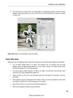
Some filter facts
Before we move on to applying a blend, here are a few things you should know about adding and
using filters:
You can apply multiple filters to an object. For example, the character in the previous exercises
could have the Drop Shadow, Glow, and Bevel filters applied to it all at once. If you need to
remove one, select that filter’s name and click the
Trash Can icon in the Filters area.
You cannot apply multiple instances of a filter to an object. You saw that in the previous exer-
cise. Each movieclip has a single Drop Shadow filter applied to it.
Filters do result in a hit on the user’s processor. Use them judiciously.
Filters applied to layers in Photoshop will be visible in Flash, but will not be editable in Flash
when the image is imported into the Flash library or to the stage.
Alpha channel video in a movieclip can have filters applied to it.
Playing with blends
The blend modes operate quite differently from the filters. If you are a Fireworks or Photoshop
user, you may already be familiar with the concept. In applications like those two, such modes are
commonly used to manipulate the colors of pixels to create new colors based on combinations with
underlying pixels.
146
CHAPTER 3
The blend modes in Flash are as follows:
Normal
Layer
Darken
Multiply
Lighten
Screen
Overlay
Hard Light
Add
Subtract
Difference
Invert
Alpha
Erase
Blend modes work like this: the pixel colors values are considered from two separate layers of an
image and mathematically manipulated by the mode to create the effect. An excellent example of this
manipulation is the Multiply mode. This mode will multiply the color values of a pixel in the source
layer with the color values of the pixel directly below it in the destination layer. The result is divided by
256, and is always a darker shade of the color. In Flash, these calculations are performed on overlap-
ping movieclips or buttons on the stage.
When applying a blend mode in Flash, keep in mind that it is not the same task as it is in Photoshop
or Fireworks. Flash lets you place multiple objects in a layer or layers. When a blend mode is applied
to a movieclip or button in Flash, it is the object directly under the movieclip or button—which could
be a photo, the color of the Flash stage, or whatever—that supplies the color for the change to the
movieclip or button.
Blends are extremely powerful creative tools in the hands of a Flash artist. Although they can only be
applied to movieclips and buttons, when applied judiciously, the blend modes can provide some rather
stunning visual effects. To apply a blend mode, you simply select the symbol to which it is to be applied—
movieclip or button—and then select the mode from the
Blend drop- down menu in the Property inspec-
tor
. Let’s look at a few of the blend modes and review some blend fundamentals along the way.
1. Open the >haj`o*bh] file in the Chapter 3 Atan_eoa folder. You will see we have put two mov-
ieclips on the stage (see Figure 3-28). The movieclips are also in separate layers named
Source and
Destination. These layers have been given those names for a reason: blending modes are applied
in a top- down manner. This means that the effect depends on the source layer’s pixels, doing
its manipulation based on those, and applying the result to the destination layer. That’s right—
anything visible under the source (including the stage) will be affected by the transformation.
147
SYMBOLS AND LIBRARIES
Figure 3-28. The pixels in the Source layer—the flowers—are used to create the effect with the pixels in the
destination layer—the Smurfs.
2. Select the image in the Source layer—the flowers—and click the twirlie in the Display area of the
Property inspector. Select Normal from the Blending drop- down menu, as shown in Figure 3-29.
The Normal mode does not mix, combine, or otherwise play with the color values.
Figure 3-29. Blend modes are applied through the Property inspector.
148
CHAPTER 3
3. With the image still selected, select Multiply from the Blending drop- down menu. As you can
see in Figure 3-30, the colors have mixed, and the darker colors make the
Source image darker.
The important thing to notice here is how the medium gray of the stage is also being used
where the
Source image overlaps only the stage. If you return the mode to Normal, select the
image in the
Destination layer, and choose the Multiply blend mode, the image will darken due
to the color of the stage. Nothing happens to the image in the
Source layer.
Figure 3-30. The Multiply mode
4. Set the blend mode of the Destination layer to Normal. Select the image in the Source layer,
set its x and y coordinates to
0 in the Property inspector, and select Lighten from the Blending
drop- down menu. In this example, the lighter color of both the
Source and Destination images
is chosen. As you can see in Figure 3-31, the lighter pixels in the
Destination image are replacing
the darker pixels in the
Source image (particularly noticeable with the white hats).
Figure 3-31. The Lighten mode
149
SYMBOLS AND LIBRARIES
5. Finally, select the image in the Source layer and select Difference from the Blending drop- down
menu. This mode is always a surprise. It works by determining which color is the darkest in
the
Source and Destination images, and then subtracting the darker of the two from the lighter
color. The result, shown in Figure 3-32, is always a vibrant image with saturated colors.
Figure 3-32. The Difference mode
6. Close the file without saving the changes.
Managing content on the stage
Now that you’ve had some fun, playtime is over. It is now time to get back to the serious issue of
managing your work. Though we have talked about using folders in layers and in the library, we really
haven’t addressed the issue of managing the content on the stage.
As we have been telling and showing you to this point, you can determine the location of objects on
the stage by dragging them around. We look upon that practice in many respects as attempting to
light your BBQ with an atom bomb. You will light the BBQ, but taking out the neighborhood is a lot
less precise than striking a match and lighting a burner. This is why we have been doing it by the num-
bers. We enter actual values into the
Property inspector or use menus to precisely place items on the
stage, and resize and otherwise manipulate content.
Grouping content
We’ll start by showing you how to group content:
1. Open the JqppuLnkbaookn*bh] file in the Chapter 3 Atan_eoa folder. Then open the Professor
movieclip from the Library.
2. Click the Professor layer. You will see that the drawing is composed of quite a few bits and
pieces (see Figure 3-33). If you wanted to move that drawing over a couple of pixels, you would
need to select each element to be moved. There is an easier method.
150
CHAPTER 3
Figure 3-33. Line art, in many cases, is the sum of its parts.
3. Select Modify ° Group or, if you are a keyboard junkie, press Ctrl+G (Cmd+G). The pieces
become one unit, as indicated by the square surrounding them.
4. Deselect the group by clicking the stage, and then click the image of the professor on the
stage. Again, you will see the box indicating that the selection is grouped, and you will also be
given the same information in the
Property inspector, as shown in Figure 3-34.
Figure 3-34. A group is indicated both on the stage and in the Property inspector.
151
SYMBOLS AND LIBRARIES
5. To ungroup the selection, select Modify ° Ungroup, or press Ctrl+Shift+G (Cmd+Shift+G).
6. Close the file without saving the changes.
Aligning objects by snapping
Now that you know how to make your life a little easier by grouping objects, let’s turn our attention to
how objects can be aligned with each other by snapping. Reopen the JqppuLnkbaookn*bh] file and click
the
Scene 1 link to return to the main timeline. You will see the movieclip and some text on the stage.
Using Snap Align
The first technique is to use Snap Align. You can switch on this very handy feature by selecting View
° Snapping ° Snap Align, and then select View ° Snapping ° Snap to Objects. When Snap Align is
switched on, the selected snapping type(s) become active. In this case—
Snap to Objects—when you
drag one object close to another object, Flash will show you a dotted line. This line shows you the
alignment of the moving object to the stationary object.
Click the words on the stage and slowly drag them toward the bottom- left corner of the movieclip.
You will see the
Snap Align indicator line (see Figure 3-35), telling you that the left edge of the text
field is aligned with the left edge of the movieclip. By dragging the text up and down the indicator
line, you can align objects at a distance. Release the mouse, and the text will snap to that line.
The dotted line appears only when Snap to Objects is the only snap type
under consideration. If other choices are also active—grid, guides, and so
on—you may not see the
Snap Align indicator.
Figure 3-35. Using Snap Align
Snapping to the grid
You can also align objects on the stage through the use of a grid. This is a handy way of precisely
positioning objects on the stage. Turn on the grid by selecting
View ° Grid ° Show Grid. When you
release the mouse, a grid will appear on the stage. This grid is an author- time feature. That means the
grid won’t appear when you publish the SWF and put it up on a web page.
152
CHAPTER 3
You can also edit the grid by selecting
View ° Grid ° Edit Grid. The Grid dialog box, shown in Figure 3-36,
will appear. Here you can change the color of the grid lines, determine if items snap to the grid, and
change the size of the squares in the grid. The
Snap accuracy drop- down menu lets you choose how
snapping to the grid lines will be managed by Flash.
Figure 3-36. Adding a grid and managing it on the stage
For the first time ever, Flash CS4 allows you to display the grid above objects on
the stage, which pleases one of the authors to no end. In previous versions of Flash,
one large background image would completely obscure the grid, even though you
could still snap to it. The option to always see the grid is super cool.
Aligning with guides
Another method for aligning objects or placing them in precise locations on the stage is to use guides.
You can add guides by dragging them off of either a horizontal or a vertical ruler. The ruler isn’t shown
by default in Flash. To turn it on, select
View ° Rulers. At 100% view, the rulers are divided into 5- pixel
units. If you need even more precise placement, zooming in to 2000% view allows you to work in units
of 0.5 pixel.
To add a guide, drag it off of either the horizontal or vertical ruler and, when it is in position, release
the mouse. To remove a guide, drag it back onto the ruler.
153
SYMBOLS AND LIBRARIES
Once a guide is in place, you can edit it by selecting
View ° Guides ° Edit Guides. This will open the
Guides dialog box (see Figure 3-37), which is quite similar to the Grid dialog box. The Snap accuracy
drop- down menu allows you to determine how close an object needs to be to a guide before it snaps
to the guide. You can also choose to lock the guides in place. Locking guides once they are in position
is a good habit to develop. This way, you won’t accidentally move them.
Figure 3-37. Rulers, guides, and the Guides dialog box
If you need to turn off the guides, select View ° Guide ° Show Guides; reselect it to turn them on
again. If you no longer need the guides, you can remove them with a single click of the mouse by
selecting
View ° Guides ° Clear Guides.
Snapping in a guide layer and to pixels
Finally, you can snap objects to items in a guide layer—not to be confused with the guides we just
discussed—and even to pixels.
Snapping to a guide layer object is nothing more than a variation on
Snap to Objects, except the layer
in question has been converted into a guide layer by right- clicking (Ctrl- clicking) a layer and selecting
Guide. What’s the difference? Guide layer content isn’t included in the SWF.
Snapping to pixels is best suited for ultra- precise positioning, which is sometimes useful with text
fields and bitmaps. In fact, you won’t even see the pixel grid until you’ve zoomed in to at least 400%.
The pixel grid is not the same as the grid explored earlier.
For better or worse, the pixel grid still appears only behind stage content. Ah,
well, can’t win ’em all.
154
CHAPTER 3
Stacking order and using the Align panel
Layers are effective tools for managing content, but there is another related concept you need to be
aware of: stacking. When multiple objects are in a layer, the objects also have a front-to- back relation-
ship with each other, appearing to be placed on top of each other, which is called the stacking order.
Stacking objects
Symbols, drawing objects, primitives, text fields, and grouped objects can be stacked. Everything else
(for example, vector shapes) essentially falls to the bottom of the pile in the layer. To accomplish
stacking, each new symbol or group added to a layer is given a position in the stack, which determines
how far up from the bottom it will be placed. This position is assigned in the order in which the sym-
bols or objects are added to the stage. This means that each symbol added to the stage sits in front,
or above, the symbols or objects already on the stage. Let’s see how this works.
1. Open the Op]_go*bh] file in the Chapter 3 Atan_eoa folder. You will
see four objects on the stage.
2. Drag the objects on top of each other. You will see a stack, as
shown in Figure 3-38. The location of each object in this stack is
a visual clue to when it was placed on the stage.
Stacking order is not fixed. For example, let’s move the circle to the top of
the stack and move the yellow pentagon under the Pac- Man shape.
3. Select the circle on the stage and select Modify ° Arrange ° Bring
to Front
. The circle moves to the top of the stack. This tells you that
the
Bring to Front and Send to Back menu items are used to move
selected objects to the top or the bottom of a stack.
4. Select the pentagon and select Modify ° Arrange ° Send Backward, as shown in Figure 3-39.
The pentagon moves under the Pac- Man symbol. This tells you that the
Bring Forward or Send
Backward
menu items can be used to move objects in front of or behind each other.
Figure 3-39. Use the menu to change the stacking order of objects.
Figure 3-38. Objects
stacked in a layer
155
SYMBOLS AND LIBRARIES
Distributing to layers
Throughout this book, we have talked about the use of layers to manage content. Obviously, stacking
objects on top of each other flies in the face of what we have said. Not so fast. There is an incredibly
useful menu item that actually allows you to bring a bit of order to the chaos. Let’s try this feature
with the Op]_go*bh] file.
1. Select all the items on the stage.
2. Select Modify ° Timeline ° Distribute to Layers. When you
release the mouse, the order of the objects in relation to each
other doesn’t change, but each object is now on its own named
layer, as shown in Figure 3-40.
3. Close the file without saving the changes.
Now that you see what you can do with this powerful menu item, you
also need to understand some rules regarding its use:
Symbols, shapes, drawing objects, primitives, text fields, and
grouped objects will be placed on their own individual layers.
For symbols, the name of the layer is based on either the sym-
bol’s library name or its instance name in the
Property inspector.
If both names are present, instance names take precedence.
For text fields, the name of the layer is based on the text con-
tent—or the text field’s instance name in the
Property inspec-
tor
. Again, instance names take precedence.
Using the Align panel
The Align panel allows you to line up and center objects, and otherwise bring order to chaos with
a click or two of the mouse.
You can access the
Align panel by either selecting Window ° Align or pressing Ctrl+K (Cmd+K). As
shown in Figure 3-41, this panel offers a number of alignment possibilities: 17 options and one toggle
button labeled
To stage. The To stage button lets you align selected objects with each other or align
them to the stage.
Figure 3-41. The Align panel
Figure 3-40. Distribute to Lay-
ers places each selected object
on its own layer.
156
CHAPTER 3
Let’s see how all of this works.
1. Open the =hecjL]jah*bh] file in the Atan_eoa folder. As you can see, the file consists of
a number of button components scattered across the stage. Open the
Align panel.
2. Select all the components, make sure the To stage button is not selected, and then click the Align
Left Edge
button in the panel (see Figure 3-42). The components all line up along their left edges.
Figure 3-42. Aligning objects verti-
cally using the Align panel
3. Click the Vertical Spacing button in the Space options, and the components will be spaced
evenly on the vertical axis. Click the
Distribute Top Edge button to even out the spacing.
Now let’s use the panel to create a button bar across the top of the stage.
4. Click the To stage button on the Align panel.
5. Select all the buttons and click the Align Top Edge button. The buttons will all pile on top of
each other at the top of the stage.
6. With the buttons still selected, click the Distribute Horizontal Center button. The buttons spread
out along the top of the stage, as shown in Figure 3-43. Not bad—two clicks, and you have
a button bar.
Figure 3-43. Two clicks is all it takes to create a button bar.
7. Close the file without saving the changes.
Masks and masking
Before we turn you loose on a project, the final subject we will be examining is the issue of masking in
Flash. As you know, masks are used to selectively show and hide objects on the Flash stage. The value
of a mask is, in many respects, not clearly understood by Flash designers. They tend to regard masking
as a way to hide stuff. They see it as an overly complicated method of doing something that could be