STEAM GENERATOR SYSTEMS: OPERATIONAL RELIABILITY AND EFFICIENCY_1 pptx
Bạn đang xem bản rút gọn của tài liệu. Xem và tải ngay bản đầy đủ của tài liệu tại đây (33.54 MB, 214 trang )
STEAM GENERATOR
SYSTEMS:
OPERATIONAL RELIABILITY
AND EFFICIENCY
Edited by Valen n Uchanin
Steam Generator Systems: Operational Reliability and Efficiency
Edited by Valentin Uchanin
Published by InTech
Janeza Trdine 9, 51000 Rijeka, Croatia
Copyright © 2011 InTech
All chapters are Open Access articles distributed under the Creative Commons
Non Commercial Share Alike Attribution 3.0 license, which permits to copy,
distribute, transmit, and adapt the work in any medium, so long as the original
work is properly cited. After this work has been published by InTech, authors
have the right to republish it, in whole or part, in any publication of which they
are the author, and to make other personal use of the work. Any republication,
referencing or personal use of the work must explicitly identify the original source.
Statements and opinions expressed in the chapters are these of the individual contributors
and not necessarily those of the editors or publisher. No responsibility is accepted
for the accuracy of information contained in the published articles. The publisher
assumes no responsibility for any damage or injury to persons or property arising out
of the use of any materials, instructions, methods or ideas contained in the book.
Publishing Process Manager Ana Nikolic
Technical Editor Teodora Smiljanic
Cover Designer Martina Sirotic
Image Copyright prochasson frederic, 2010. Used under license from Shutterstock.com
First published March, 2011
Printed in India
A free online edition of this book is available at www.intechopen.com
Additional hard copies can be obtained from
Steam Generator Systems: Operational Reliability and Efficiency,
Edited by Valentin Uchanin
p. cm.
ISBN 978-953-307-303-3
free online editions of InTech
Books and Journals can be found at
www.intechopen.com
Part 1
Chapter 1
Chapter 2
Chapter 3
Chapter 4
Chapter 5
Chapter 6
Chapter 7
Preface IX
Material Degradation and Fracture Mechanisms 1
Degradations of Incoloy 800
Steam Generator Tubing 3
Dumitra Lucan
Analysis of Oxide on Steam Generator Tubing
Material in High Temperature Alkaline Leaded Solution 21
Dong-Jin Kim, Seong Sik Hwang,
Joung Soo Kim, Yun Soo Lim,
Sung Woo Kim and Hong Pyo Kim
Burst and Leak Behaviour
of SCC Degraded SG Tubes of PWRs 41
Seong Sik Hwang, Man Kyo Jung,
Hong Pyo Kim and Joung Soo Kim
In-situ Monitoring of SCC
of Alloy 600 SG Tubing in PWR using EN Analysis 61
Sung-Woo Kim, Hong-Pyo Kim,
Seong-Sik Hwang and Dong-Jin Kim
Effect of Long-Term Thermal Influence
on Mechanical Properties of Welded Joints
for Carbon Steels used in Power Engineering 75
Zilvinas Bazaras and Boris Timofeev
Primary to Secondary Leakage
at PSB-VVER Test Facility,
Simulated by CATHARE 2 Code 99
Luben Sabotinov and Patrick Chevrier
Reliability of Degraded Steam Generator Tubes 117
Leon Cizelj and Guy Roussel
Contents
Contents
VI
Nondestructive Evaluation and Diagnostics 143
The Development of Eddy Current Technique
for WWER Steam Generators Inspection 145
Valentin Uchanin and Vladimir Najda
Detection of Magnetic Phase
in the Steam Generator Tubes of NPP 165
Duck-Gun Park, Kwon-Sang Ryu and Derac Son
Optical Methods for On-line Quality Assurance
of Welding Processes in Nuclear Steam Generators 185
Adolfo Cobo, Jesús Mª Mirapeix, David Solana,
Alfonso Álvarez-de-Miranda, Pilar-Beatriz García-Allende,
Olga Mª Conde and José Miguel López-Higuera
Heat Transfer and Coolant Flow Processes 203
Countercurrent Flow in a PWR Hot Leg
under Reflux Condensation 205
Noritoshi Minami, Michio Murase and Akio Tomiyama
Evaluation of Non-condensable Gas Recirculation Flow in
Steam Generator U-tubes during Reflux Condensation 227
Michio Murase, Takashi Nagae and Noritoshi Minami
Coolant Channel Module CCM. An Universally
Applicable Thermal-Hydraulic Drift-Flux
Based Separate-Region Mixture-Fluid Model 247
Alois Hoeld
The Thermal-hydraulic U-tube Steam Generator
Model and Code UTSG-3 (Based on the Universally
Applicable Coolant Channel Module CCM) 289
Alois Hoeld
Computation of Flows in Steam Generators 327
Jonas Bredberg
Semi Analytical Analysis of Steady State
Condition of Steam Generator 353
Zaki Su’ud
Safety and Maintenance Management 369
Issues for Nuclear Power Plants Steam Generators 371
Lucia Bonavigo and Mario De Salve
Part 2
Chapter 8
Chapter 9
Chapter 10
Part 3
Chapter 11
Chapter 12
Chapter 13
Chapter 14
Chapter 15
Chapter 16
Part 4
Chapter 17
Contents
VII
Shielding Analysis of the Secondary Coolant
Circuit of Accelerator Driven Systems 393
Toshinobu Sasa and Hiroyuki Oigawa
Starting Fast Reactors Again 413
Didier Costes
Chapter 18
Chapter 19
Pref ac e
Operational productivity, reliability and safety of power generating plants are
strongly connected with eff ectiveness and behaviour of applied steam generator
system. It is especially crucial for nuclear power plants with two circuit heat ex-
change arrangement when only few millimeters of tube wall material separate the
primary and secondary circuits. Whereas the fi rst circuit is connected with reactor
core and has high level of radioactive contamination, the tube integrity preserva-
tion is very important for ecological safety. In addition, it is necessary to note that
the steam generator components are exposed to permanent and simultaneous infl u-
ences of high temperature, pressure, stresses and corrosion-erosion wear.
Therefore, the material degradation of steam generator components in a common
sense (united diff erent corrosion phenomena, fatigue cracking, structure changes
and another fracture processes) is one of the most relevant and inseparable factor for
appearance of the leakage between the primary and the secondary circuits.
Because of long-term operation and fracture inevitability the role of nondestruc-
tive evaluation based on diff erent physical phenomena for on-time defect detection
to prevent possible accidents is also very signifi cant. At present, the eddy current
method became the most applicable for steam generator tube operational inspection
along the full tube length with application of diff erent types of internal probes due
to many advantages in comparison with other methods.
By optimizing of the heat transfer, cooling and fl aw processes on the base of theo-
retical simulation and computer codes the higher level of the nuclear power plant
effi ciency and availability can be achieved.
This book consists of 19 chapters allocated between four parts:
• Material degradation and fracture mechanisms,
• Nondestructive evaluation and diagnostics,
• Heat transfer and coolant fl aw processes,
• Safety and maintenance management.
The authors from diff erent countries all over the world (Germany, France, Italy Ja-
pan, Slovenia, Indonesia, Belgium, Romania, Lithuania, Russia, Spain, Sweden, Ko-
rea and Ukraine) prepared chapters for this book. Such a broad geography indicates
the high signifi cance of considered subjects.
X
Preface
The book is intended for practical engineers, researchers, students and other people
dealing with the reviewed problems. We hope that the presented book will be ben-
efi cial to all readers and initiate further inquiry and development with aspiration
for be er future.
In the name of all authors, I want to express our gratitude to publishing process
manager Ms. Ana Nikolic for patience and understanding
Dr. Valentin Uchanin
Karpenko Physico-Mechanical Institute of National Academy of Sciences
Department of Structural Fracture Mechanics and Material Properties Optimization
Lviv,
Ukraine
Part 1
Material Degradation
and Fracture Mechanisms
1
Degradations of
Incoloy 800 Steam Generator Tubing
Dumitra Lucan
Department of Corrosion and Circuits Chemistry,
Institute for Nuclear Research, POB 78, Pitesti
Romania
1. Introduction
In our days, the nuclear energy becomes more and more important. The efficient operation
of a Nuclear Power Plant (NPP) supposes the assurance of the performances established by
design for all entire life of the NPP key components. Steam Generator (SG) is one of the key
components for a NPP because this equipment assures the separation boundary between the
primary and secondary circuit and its unavailability suppose the NPP shutdown. The
synergetic action of the high pressures and temperatures, constraints (stresses, vibrations)
and the chemical parameters of the cooling agents make the steam generator susceptible for
more types of degradations. Because of the unavailability of the measures for monitoring
and mitigation of these degradations the performances of the steam generators decrease and
determine direct and indirect losses. The replacement of the steam generator is very
expensive and very difficult. For these reasons it becomes necessary the assurance of the
steam generator performances for the entire life established by design, 30 years with the
possibility of extension to 40 or 60 years.
The optimization of the steam generator operation, by implementation of the management
complex system for the monitoring of the operation processes, periodical inspections, and
preventive maintenance determine economies by order of hundreds of millions dollars, for
entire life of a nuclear power plant.
In this scope it is very important to intensify of the applicative research in the purpose of
establishing the newest solutions, methods, mechanisms in order to characterize the specific
processes for the operation of the steam generator. The principal objective of the research
consists in the establishing of the fundamental knowledge, theories, methods and models
necessary for qualitative and quantitative characterization of steam generator degradation
processes. The complementary research activity should be oriented towards the
management of ageing and, implicitly, towards the preservation of the steam generator
structural integrity.
The principal objective of the work presented in this chapter consists in the characterization
of specific processes and mechanisms referring to steam generator tubing degradation.
The specific objectives are the following: the establishment of the main corrosive
degradation mechanisms which contribute at steam generator tubing material (Incolloy-800)
failures; knowledge of the phenomena which appear in steam generator because of the
material/environment interaction; elucidation of corrosion product release, transport and
Steam Generator Systems: Operational Reliability and Efficiency
4
deposition mechanisms in the secondary circuit of the steam generator, which depend by
physical-mechanical properties of materials and physical-chemical properties of thermal
agent (temperature, pressure, pH, electrochemical potential).
All steam generator tube failures result in the transfer of the radioactive materials from the
primary coolant circuit to the steam generator secondary circuit, and necessitate downtime
to locate and plug failed tubes. For the particular case of the CANDU plants, any steam
generator tube failure results in an additional economic penalty through the loss of heavy
water. Nearly all the failures were attributed to secondary side water chemistry conditions
and excursions, many of which resulted from condenser cooling water ingress.
The investigation of the structural materials corrosion in correlation with the water
chemistry, as well as the impurities and corrosion products concentration and deposition
and their removing from the CANDU steam generators is a very active field and both the
experimental works and the understanding of the mechanisms involved are submitted to
some rapid changes and permanently open to the research. To provide information about
the corrosion behaviour of the structural materials from CANDU steam generators under
normal and abnormal conditions of operation and to identify the failure types produced by
corrosion were performed a lot of corrosion experiments. These experiments consisted in
chemical accelerated tests, static autoclaving and electrochemical investigations.
The goal of this work consists in the assessment of corrosion behaviour of the tubes material,
Incoloy-800, at normal secondary circuit parameters ((temperature - 260°C, pressure -
5.1MPa). The testing environment was the demineralised water without impurities, at
different pH values regulated with morpholine and cyclohexylamine (all volatile treatment
– AVT).
The results are presented like micrographics and graphics representing weight loss of metal
due to corrosion, corrosion rate, total corrosion products formed, the adherent corrosion
products, released corrosion products, release rate of corrosion products and release rate of
the metal.
This work contributes to the establishing of causes that produced components degradation,
the knowledge of mechanisms degradation, evaluation of corrosion evolution in time by
extrapolation of obtained results and estimation of remaining safe operation life for the
nuclear power plant key-components.
The knowledge of corrosion behavior of structural materials of equipments from nuclear
power plants gives the possibility to effectuate of some correct diagnosis and following of
necessary measures to prevent and diminish the ageing process of which the evolution
supposes some considerable economic costs.
2. Types of corrosion specific to the steam generator
The maintenance operations in a Nuclear Power Plant are particularly complex and difficult
due to its specific nature. It is, therefore, necessary that by an appropriate design and a
proper choice of construction materials assisted by a correct operation, long operation
periods be ensured, (IAEA, 1997).
The important steps of a maintenance program for NPP related facilities are the
disassembling and the inspection of components in order to:
1. detect of the problems that occurred after the last inspection, including:
a. the determination of their causes;
b. the notification of the supplier if a material defect is involved;
Degradations of Incoloy 800 Steam Generator Tubing
5
2. correct the actions proposal considering the estimated period that the component is still
able to operate, implying either the elimination of the main defect causes or the re-
design of the part.
3. implement corrective measures by:
a. the cleaning operations;
b. the repairs;
c. the replacement of the defective component, if possible by an upgraded one, if this
exists.
Maintenance should be done periodically, according to a pre-established plan. In this way,
besides repairing the known defects, others can be identified, as well as their causes and the
corrective actions required. Maintenance is especially difficult at nuclear facilities due to the
presence of radiation fields and to the complexity of the facilities.
The SG tubing degradation caused by corrosion and other age-related mechanisms
continues to be a significant safety and cost concern for many SGs. The understanding SG
degradation mechanisms is the key to effective management of SG ageing and consists in
the knowledge of SG materials and these one properties, stressors and operating conditions,
like degradation sites and wear mechanisms.
The Steam Generators, equipments that ensure the connection between the primary and the
secondary circuits, create several safety problems during operation, mainly due to corrosion
and mechanical damages. Maintenance is also difficult in the SG because of the limited
access to various components and because of the presence of the high radiation field existing
on the side of the primary circuit.
For manufacturing the SG, several types of steels are used, whose coexistence in the
environmental conditions of the steam generator arises special problems with respect to
corrosion.
Corrosion and the mechanical damage in the SG are the result of complex interaction
between various factors:
- strict control of water chemistry;
- adequate thermo-hydraulic design;
- selection of generator construction materials;
- utilisation of compatible materials for the entire secondary circuit;
- conditions of achieving equipments and facilities;
- the operation technique.
This is why a careful analysis of corrosion problems is required, necessary both from an
economic point of view and for the safe operation.
Materials and environment conditions specific to the steam generator
The most important element in selecting the SG construction materials is their resistance to
corrosion in special operation conditions.
The main operation parameters of the SG are:
D
2
O H
2
O
t
in
= 309
0
C t
in
= 187.2
0
C
t
ou
= 290
0
C t
ou
= 260
0
C
P
in
= 9.887 MPa P
in
= 6.700 MPa
P
ou
= 9.625 MPa P
ou
= 4.695 MPa
Steam Generator Systems: Operational Reliability and Efficiency
6
Incoloy-800 is utilised for tubes having in view the following reasons:
• presents good resistance to stress corrosion cracking, as compared to Inconel-600;
• releases a much smaller amount of radioactive products in the primary circuit;
• has a high resistance to cracking corrosion in alkaline environment (20% higher than
Inconel-600).
The SG includes the following types of steels: Incoloy-800 (tubes), Inconel-600 (tubesheet
cladding), stainless steel SA 240-410S (intermediate supports), carbon steel SA 516-gr. 70
(shells), carbon steel SA 508 cl.2 (tubesheet).
The chemical control of water is done by maintaining of the parameters between certain
limits that influence the corrosion behaviour of SG materials: the amount and composition
of corrosion products, impurities (especially dissolved salts) and oxidation agents.
Although the corrosion products are not directly responsible for corrosion, they are the
main cause of the accumulation and concentration of aggressive species that can lead to a
variety of corrosion forms. The corrosion products will be carried from the SG in the entire
system, determining the occurrence of corrosion-related inconveniences, even and in areas
where apparently this would not be possible. The main source of penetration of oxygen and
impurities is coolant leakage from the condenser. The impurities concentration is
responsible for the initiation, propagation and acceleration of corrosion processes of the SG
tubing. This is why it is compulsory a careful control of water chemistry, of reactants
addition and of the cleaning degree after maintenance or repairs.
Degradations due to corrosion can be divided into two large groups: degradations that end
up in cracking and those which do not imply cracking. Corrosive degradations produced in
the absence of a significant stress (applied, residual or due to corrosion products deposition)
will not end up in cracking, except for certain cases such as intergranular corrosion.
Corrosion that does not imply cracking can appear under the following three specific forms:
1. generalised corrosion;
2. localised corrosion (pitting of Incoloy-800 tubes);
3. crevice corrosion.
The corrosion cracking degradations are favoured by the following conditions:
a. stress corrosion cracking (SCC) under constant stress in the thermally affected area
close to welds.
b. SCC under monotonous increasing stress, during denting occurrence in the SG.
c. fatigue (wear) corrosion of Incoloy-800 tubes under cyclic stress.
Generalised corrosion
Many research workers have demonstrated that stainless steels and nickel-rich alloys
present in the SG undertake a generalized corrosion; their corrosion rates vary in time
approximately parabolically.
The corrosion products release rates decrease in time, following various kinetics.
Generalized corrosion prevails in the case of carbon steels.
Since most of the studies were performed in static autoclaves, particular care is required if
one desires the extrapolation of results for typical conditions in nuclear facilities, where the
influence of the thermal transfer and of coolant circulation is added, due to thermo-
hydraulic parameters.
The corrosion mechanism of these materials consists in the formation of two overlapped
layers of compounds, the outer one being crystalline. Based on this model, Lesurf assumed
that the total rate of the film formation is controlled by the migration rate of iron species
Degradations of Incoloy 800 Steam Generator Tubing
7
soluble in water through the pores of the oxide layer: part of the oxidized iron is included in
the magnetite formed in the area of contact with the metallic under-layer (forming thus the
inner film), while the remaining is carried into the solution, at the outer edge of the oxide
layer where it can precipitate, forming the crystalline outer film, or its release can occur in
the solution mass, precipitating at random.
The corrosion products entailed in the working fluid will deposit in the restricted
circulation regions, thus contributing to the initiation of corrosion in those areas.
Localized corrosion
Localized corrosion supposes the fast local dissolving on a significant depth and it can
induce destruction of the base material.
Localized corrosion is an extremely dangerous phenomenon, since it usually takes place in
less aggressive environments - where generalized corrosion is negligible - and it is quite
difficult to be detected, due to its location and very small dimensions.
Denting corrosion
If the cooling water was phosphate-treated and then treated with volatile amines (AVT) one
noticed the occurrence of a corrosive attack called denting. This means the deformation of
Incoloy-800 tubing due to the increase in volume of corrosion products formed between the
intermediary carbon steel support plate and the Incoloy-800 tube.
Around each Incoloy-800 tube that penetrates the intermediary support plate there is a gap
of a few tenths of a millimetre. Within this space an accelerated corrosion of carbon steel
was noticed, resulting in magnetite. Magnetite accumulates in time and exerts a
compression force on the tube; this one can distort, leading to a local stiction in the tube,
called dent.
This denting corrosion can also lead to the blocking of the sondes used in eddy-current
examinations of the tubular bundle.
Consequently, denting is a form of corrosion in the crevice between the tube and the
support plate, where an initial concentration of acid species (chlorides, sulphates) takes
place.
The oxygen, copper and nickel ions act as accelerators of denting. The occurrence of this
event can be avoided by choosing appropriate construction solutions for the intermediate
supports, utilization of stainless steel for these supports, treatment, from the very beginning,
with volatile amines and removal of copper from the composition of the secondary circuit
equipments.
Corrosion under the impurities layer (wastage)
Another type of corrosion likely to occur when treating water with phosphates is the
"wastage" corrosion. This one takes place under the deposits on the tube surface, in the areas
where wet and dry periods alternate.
It is known that during SG operation a sludge accumulates on the tubesheet, reaching a
height of 30 cm or more. As the sludge content increases, the coolant cannot reach the
surface in order to replace the evaporated liquid. The temperature in this region becomes
equal to that of the coolant. The area where the strongest corrosion is encountered is the
interface, where wetting and drying alternate, which determines the thinning of the Incoloy-
800 tubes.
Using adequate constructive solutions can diminish the phenomenon.
Steam Generator Systems: Operational Reliability and Efficiency
8
Pitting corrosion
Pitting corrosion can appear both on the Incoloy-800 tubing and on the tubesheet. Thus, pits
with a depth of 0.02-0.05 mm have been observed on the Incoloy-800 tubes in the crevices
where denting occurred, determined by a high concentration of chlorides. Pitting was also
observed on the tubesheet, especially under the sludge.
Stress corrosion cracking (SCC)
This type of corrosion was more frequently identified on the U-shaped upper region of
Incoloy-800 tubes, but cracks have been noticed in other areas, too.
The crack that appeared in the U-bend region has been generally initiated from the inside of
the tube. The examination of such tubes shows that these cracks initiated on the side of the
primary agent are of intergranular nature, oriented along the longitudinal axis of the tubes.
The factors involved in the cracking of the U-bend region are:
• microstructural factors, features referring to material strength and hardness;
• residual or latent stresses that emerge during fabrication, bending and installation;
• shape of the tube, bending radius resulting from processing;
• the extent and frequency of cycling, shape of strains induced during SG operation;
• environment chemistry or environment factors.
The inspection of cracks on the unbended side of damaged tubes revealed that SCC
appeared in points where denting progressed to such extent so that the tubes became
ovalized or wave-shaped, instead of circular. Cracks occurrence was noticed in places where
the highest strain was applied; they were initiated either on the inner or on the outer
surface. A third type of SCC initiated by granular attack from the interior is in the transfer
region from the expanded area to the non-expanded one - at the joint with the tubesheet -
where high strains affect the tube walls.
Mechanical degradations of the SG tubing
Mechanical degradations that may alter SG tubing can be divided into: vibrations wear
(fretting) and fatigue wear.
These degradations belong to the category of localized attack.
The strength that determines them is produced by tubes vibration, induced by flow
circulation.
This time, corrosion appears as an additional factor that accelerates mechanical degradation
of the tubes; it acts synergistically. The effect of the synergetic action of the two factors
varies from the erosion of passive films on the materials surface to the accelerating effects of
certain aggressive environments on the quality of the metal.
Due to vibrations in the region of contact tube - tubesheet, the tube can notably reduce its
thickness, sometimes displaying cracks. Vibrations are also responsible for the excessive
degradation of anti-vibration bars used in some SG: their replacement is prescribed. In the
case of cracks initiated on defects (for example in regions where local thinning of tubing
walls took place) a transgranular attack was identified on the tubes outer surface. The
mechanism of these cracks includes the fatigue fretting corrosion in the presence of
corrosive species in the environment, (Lucan, D. 2006; Lucan, D. et al., 2007; Lucan, D. et al.,
2008).
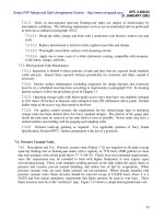
Fig. 1. is a schematic layout of corrosive attacks specific to Steam Generators.
Degradations of Incoloy 800 Steam Generator Tubing
9
Fig. 1. Types of corrosion specific to the steam generator, (IAEA, 1997)
3. Experimental
The generalized corrosion is an undesirable process because it is accompanied by deposition
of the corrosion products which affect the steam generator performances. It is very
important to understand the corrosion mechanism with the purpose of evaluating the
quantities of corrosion products which exist in the steam generator after a determined
period of operation, (IAEA, 1997).
The nickel-based alloys (Incoloy-800) are currently used as corrosion resistant materials in
the nuclear industry because their corrosion rates are quite low. This behavior is attributable
to the protective character of the oxide film formed on their surface when the contact with
the pressurized high-temperature water environment is realized. Nevertheless, oxidation
processes or deposition of corrosion products can promote the development of particular
corrosion problems. These phenomena result from changes in the structure of the oxide
films throughout the cooling circuit, (Iglesias & Calderon, 2003).
Steam Generator Systems: Operational Reliability and Efficiency
10
Corrosion experiments included in the present work have been carried out on the Incoloy-
800 samples by autoclaving in static autoclaves at parameters specific for the secondary
circuit of the CANDU steam generator: temperature 260ºC, pressure 5.1MPa. The specimens
used were from Incoloy-800, steam generator tube, (15.9mm outside diameter and 1.13mm
wall thickness) which was sectioned on the diameter into 15 mm long pieces polished with
grit papers and cleaned ultrasonically. The testing environments utilized were
demineralised water with pH = 7.5, 8.5 and 9.5 (AVT). The testing periods were 240h, 2050h
and 3550h. Demineralised water had a dissolved oxygen content was below 2ppm (oxygen
was released by thermal degassing at 100ºC). The water pH and conductivity were
measured with Multi – Channel Analyser CONSORT C835. Experimental work included:
gravimetric analyses, optical microscopically analyses and electrochemical measurements
(potentiodynamic polarization). The weight modifications due to oxidation or corrosion
products removal by different methods were measured using a Shimadzu AUW 220
analytically balance providing a precision of ±0.01 mg. The surfaces morphologies and the
cross sections of the corrosion samples were analyzed with the optical microscope
OLYMPUS GX 71. The corrosion kinetic was additionally evaluated by potentiodynamic
measurements using a PAR 2273 device.
4. Results and discussions
The goal of the work consists in the assessment of the kinetics corrosion for the Incoloy-800 -
material of the tubes - tested in demineralised water with different pH values and the
experimental results processing with the purpose of including results in a future database of
a steam generator. To investigate the water chemistry effects on characteristics of corrosive
films formed on Incoloy-800 material, a number of corrosion experiments by electrochemical
methods and static autoclaving were performed. The electrochemical determinations were
performed by potentiostatic method in aqueous solutions with different pH, at room
temperature, (Lucan, D., 2010).
a)
b)
Fig. 2. Surface morphology (x200) (a) and aspect of the superficial layer (x1000) (b) for
Incoloy-800 exposed for 1680h in demineralised water, pH=7.5, T=260
0
C and p=5.1MPa
Degradations of Incoloy 800 Steam Generator Tubing
11
The chemical composition of Incoloy-800 in percent weight is: C=0.02%, Mn=0.64%,
Si=0.49%, S=0.01%, Ni=33.40%, Cr=21.90%, Cu=0.01%, Al=0.24%, Ti=0.41% and Fe=42.88%.
Some examples of experimental results for the testing of the Incoloy-800 samples for
different times in demineralised water environments with pH=7.5, pH=8.5 and pH=9.5
(AVT) at secondary circuit steam generator specifically parameters (260
0
C and 5.1MPa) are
presented in the Fig.2 ÷ Fig.4.
a)
b)
Fig. 3. Surface morphology (x200) (a) and aspect of the superficial layer (x1000) (b) for
Incoloy-800 exposed for 3600h in demineralised water, pH=8.5, T=260
0
C, p=5.1MPa
a)
b)
Fig. 4. Surface morphology (x200) (a) and aspect of the superficial layer (x1000) (b) for
Incoloy-800 exposed for 3192h in demineralised water, pH=9.5, T=260
0
C, p=5.1MPa
The exposure times for the metallographic analysis of samples tested at a pH=7.5 were:
264h, 456h, 696h, 960h and 1680h. For the Incoloy-800 samples, tested for 264h in
demineralised water at a pH=7.5 a uniform, continuous, adherent oxide layer is noticed,
with thickness smaller than or equal to 0.6μm. When the testing time was 456h in the same
Steam Generator Systems: Operational Reliability and Efficiency
12
conditions the presence of the oxide is noticed on samples surface, brown-red in colour. The
samples surface is entirely covered by oxide and there are no uncovered spots while the
visual aspect is almost identical for the entire surface. Thickness of the oxide layer is about
0.8 μm. The oxide layer on the samples tested for 696h is uniform, continuous, adherent,
while its thickness ranges between 0.6μm÷1.2μm. The results of the 960 hours exposure was
the occurrence of an oxide layer with a thickness of 0.9μm÷1.5μm.
The thickness of the oxide layer existing on the samples tested for 1680h is about 3μm.
The aspect of the surface and film formed on the samples tested 1680h in demineralised
water at a pH=7.5 are presented in Fig.2. The exposure times for the metallographic analysis
of the samples tested at a pH=8.5 were: 240h, 720h, 1200h, 1416h, 1656h, 1824h, 2064h, and
3600h. On the Incoloy-800 samples, tested for 240h in demineralised water with a pH=8.5
adjusted with morpholine and cyclohexylamine, at 260
0
C and a pressure of 5.1MPa a
uniform, continuous and adherent oxide layer is noticed, whose thickness is smaller than or
equal to 1.9μm. The surface morphology for some samples exposed for 240h in
demineralised water at a pH=8.5 (AVT) at parameters specific to the steam generator
secondary circuit shows the presence of the oxide, its colour being brown-red. The samples
surface is completely covered by oxide and there are no uncovered spots, while the visual
aspect is almost identical for the entire surface. It is to be noticed that the oxide layer for the
samples tested 720h in demineralised water with a pH=8.5 is in this case, uniform,
continuous, adherent and its thickness ranges between 0.7μm and 0.8μm. The oxide is
uniform, with brown-red shadows and formed in continuous film on the samples surface.
For the Incoloy-800 samples tested for 1200h in demineralised water with a pH=8.5 the
result of the exposure was the formation of an oxide layer with a uniform thickness of
1.2μm. In this case the oxide uniformity is noticed. The aspect of the oxide layer existing on
the samples tested 1416h is shown that the film thickness on these samples is about 0.8μm.
The surface morphology for the samples exposed for 1416h has a uniform aspect.
The aspect of the oxide layer existing on the surface of samples tested for 1656h in
demineralised water with pH=8.5 is uniform, continuous and adherent. The uniformity and
continuity of the oxide film is observed and the surface morphology for the samples
exposed for 1656h in demineralised water with pH=8.5. The oxide film is uniform,
continuous, adherent and has a thickness smaller than 2.6μm for a sample exposed for 1824h
in demineralised water with a pH=8.5 in conditions specific to the operation of the
secondary circuit.
The aspect of the oxide layer on the surface of samples tested for 2064h in demineralised
water with a pH=8.5 is uniform, continuous and adherent. The uniformity and continuity of
the oxide layer can be noticed by the surface morphology of samples exposed for 3600h in
demineralised water with a pH=8.5, Fig.3. The oxide layer is uniform, continuous and
adherent and has a thickness smaller than 3.5μm. The aspect of the oxide layer and the
surface morphology, respectively, for a sample exposed for 3192h in demineralised water at
a pH=9.5 under operating conditions specific to the secondary circuit are presented in Fig.4.
4.1 Comparison of outputs of tests performed at pH=7.5, pH=8.5 and pH=9.5
After autoclaving operation the samples were descaled in two stage alkaline permanganate
– citrox, (Taylor, 1977). Fig.5 ÷ Fig.11 comparatively present the corrosion kinetics for: metal
loss by corrosion; corrosion rate; totally formed corrosion products; adherent corrosion
products, released corrosion products; corrosion products release, and the release rate of
Degradations of Incoloy 800 Steam Generator Tubing
13
metal at a pH=7.5, pH=8.5 and pH=9.5, respectively. The Table 1 presents the equations for
the corrosion kinetics. For the weight loss due to corrosion and corrosion rate it is noticed
that, in the case of a pH=9.5 these have the smallest values (Fig.5 and Fig.6), (Lucan et al.,
1998; Lucan et al., 2001; Lucan et al., 2003; Lucan et al., 2005; Cojan et al., 2008). The results
are confirmed by the experiments presented in articles from specialty journals, (Taylor, 1977;
Stellwag, 1998; Iglesias & Calderon, 2003).
No. Parameter pH=7.5 pH=8.5 pH=9.5
1
Loss of metal by
corrosion
y=0.1249ln(x)+0.0337 y=0.2201x
0.2705
y=0.10501x
0.277
2
Corrosion rate
y=0.2275x
-0.831
y=0.3439x
-0.8377
y=0.2579x
-0.8434
3
Total corrosion
products
y=0.1626ln(x)+0.1055
y=0.2417ln(x)-
0.0648
y=0.0973lnx+0.2721
4
Adherent corrosion
products
y=0.2924x
0.142
y=0.2962x
0.2602
y=0.0757lnx+0.2827
5
Released corrosion
products
y=0.051ln(x)–0.0328
y=0.0296ln(x)-
0.0461
y=0.0216lnx–0.0106
6
Release rate of
corrosion products
y=0.0206x
–0.4336
y=0.0217x
–0.6715
y=0.0168x
–0.6354
7
Release rate of metal
y=0.0031x
–0.6542
y=0.0174x
–0.7571
y=0.0031x
–0.6715
Table 1. The equations for the kinetic corrosion specific parameters
0.00
0.10
0.20
0.30
0.40
0.50
0.60
0.70
0.80
0.90
1.00
0 50 100 150 200
Time (days)
Loss weight (g/m2)
pH=8.5
pH=7.5
pH=9.5
Fig. 5. Loss of metal by corrosion vs. time
Also, in the case of totally formed corrosion products the smallest values have been obtained
in exposure in solution at a pH=9.5 (Fig.7). In the case of adherent corrosion products, the
smallest values have been reached for the solution with a pH = 7.5 (Fig.8), but the values for