MAGNESIUM ALLOYS DESIGN, PROCESSING AND PROPERTIES_1 pdf
Bạn đang xem bản rút gọn của tài liệu. Xem và tải ngay bản đầy đủ của tài liệu tại đây (27.24 MB, 174 trang )
MAGNESIUM ALLOYS ͳ
DESIGN, PROCESSING
AND PROPERTIES
Edited by Frank Czerwinski
Magnesium Alloys - Design, Processing and Properties
Edited by Frank Czerwinski
Published by InTech
Janeza Trdine 9, 51000 Rijeka, Croatia
Copyright © 2011 InTech
All chapters are Open Access articles distributed under the Creative Commons
Non Commercial Share Alike Attribution 3.0 license, which permits to copy,
distribute, transmit, and adapt the work in any medium, so long as the original
work is properly cited. After this work has been published by InTech, authors
have the right to republish it, in whole or part, in any publication of which they
are the author, and to make other personal use of the work. Any republication,
referencing or personal use of the work must explicitly identify the original source.
Statements and opinions expressed in the chapters are these of the individual contributors
and not necessarily those of the editors or publisher. No responsibility is accepted
for the accuracy of information contained in the published articles. The publisher
assumes no responsibility for any damage or injury to persons or property arising out
of the use of any materials, instructions, methods or ideas contained in the book.
Publishing Process Manager Iva Lipovic
Technical Editor Teodora Smiljanic
Cover Designer Martina Sirotic
Image Copyright Masekesam, 2010. Used under license from Shutterstock.com
First published January, 2011
Printed in India
A free online edition of this book is available at www.intechopen.com
Additional hard copies can be obtained from
Magnesium Alloys - Design, Processing and Properties, Edited by Frank Czerwinski
p. cm.
ISBN 978-953-307-520-4
free online editions of InTech
Books and Journals can be found at
www.intechopen.com
Chapter 2
Chapter 3
Chapter 4
Chapter 5
Chapter 6
Chapter 7
Chapter 8
Chapter 9
Preface IX
Hardening and Softening in Magnesium Alloys 1
Pavel Lukáč and Zuzanka Trojanová
Deformation Structures
and Recrystallization in Magnesium Alloys 21
Étienne Martin, Raj K. Mishra and John J. Jonas
Mechanisms of Plastic Deformation
in AZ31 Magnesium Alloy Investigated
by Acoustic Emission and Electron Microscopy 43
Miloš Janeček and František Chmelík
Thermo - Physical Properties of Iron - Magnesium Alloys 69
Krisztina Kádas, Hualei Zhang, Börje Johansson,
Levente Vitos and Rajeev Ahuja
Precipitates of γ–Mg17Al12 Phase in AZ91 Alloy 95
Katarzyna N. Braszczyńska-Malik
Evaluation Method for Mean Stress Effect
on Fatigue Limit of Non-Combustible Mg Alloy 113
Kazunori MORISHIGE, Yuna MAEDA,
Shigeru HAMADA and Hiroshi NOGUCHI
Fatigue Endurance of Magnesium Alloys 129
Mariana Kuffová
Ultrasonic Grain Refinement
of Magnesium and Its Alloys 163
M. Qian and A. Ramirez
Bulk Ultrafine-Grained Magnesium Alloys by SPD
Processing: Technique, Microstructures and Properties 187
Jinghua JIANG and Aibin MA
Contents
Contents
VI
Mechanical Properties of Fine-Grained
Magnesium Alloys Processed by Severe Plastic Forging 219
Taku Sakai and Hiromi Miura
Grain Refinement of Magnesium Alloy by Multiaxial
Alternative Forging and Hydrogenation Treatment 245
Kunio Funami and Masafumi Noda
Improving the Properties of Magnesium Alloys
for High Temperature Applications 265
Kaveh Meshinchi Asl
Microstructure and Properties
of Elektron 21 Magnesium Alloy 281
Andrzej Kiełbus
Magnesium Sheet; Challenges and Opportunities 297
Faramarz Zarandi and Stephen Yue
Contemporary Forming Methods of the Structure
and Properties of Cast Magnesium Alloys 321
Leszek Adam Dobrzański, Tomasz Tański, Szymon Malara,
Mariusz Król and Justyna Domagała-Dubiel
The Recent Research on Properties of Anti-High
Temperature Creep of AZ91 Magnesium Alloy 351
Xiulan Ai and Gaofeng Quan
Hot Forming Characteristics of Magnesium Alloy AZ31
and Three-Dimensional FE Modeling and Simulation
of the Hot Splitting Spinning Process 367
He Yang, Liang Huang and Mei Zhan
Study on Thixotropic Plastic Forming
of Wrought Magnesium Alloy 389
Hong Yan
Study on Semi-solid Magnesium Alloys Slurry
Preparation and Continuous Roll-casting Process 407
Shuisheng Xie, Youfeng He and Xujun Mi
Design and Development
of High-Performance Eco-Mg Alloys 431
Shae K. Kim
Welding and Joining of Magnesium Alloys 469
Frank Czerwinski
Chapter 10
Chapter 11
Chapter 12
Chapter 13
Chapter 14
Chapter 15
Chapter 16
Chapter 17
Chapter 18
Chapter 19
Chapter 20
Chapter 21
Contents
VII
High Strength Magnesium Matrix
Composites Reinforced with Carbon Nanotube 491
Yasuo Shimizu
Magnesium Alloys Based Composites 501
Zuzanka Trojanová, Zoltán Száraz,
Peter Palček and Mária Chalupová
Chapter 22
Chapter 23
Pref ac e
The global manufacturing using light metals is on the edge of substantial growth and
opportunity. Among light metals of strategic importance that include titanium, alumi-
num and magnesium the la er one with its density of 1.74 g/cm
3
is the lightest metal,
commonly used for structural purposes. In addition to low density, magnesium is rec-
ognized for its high strength to weight ratio, high electrical and thermal conductivity,
vibration damping, biocompatibility, recycling potential and esthetics. Magnesium is
used in the form of alloys and usually subjected to casting, rolling, extruding or forg-
ing. Further fabrication frequently involves a wide range of operations such as form-
ing, joining, machining, heat treatment or surface engineering.
In parallel with application expansion there is also tremendous interest in magnesium
research at academic and industrial levels. A number of conferences devoted to mag-
nesium and research papers published indicate that magnesium-related activities are
present at large number of universities and government institutions. Recent downturn
in economy that reduced industrial research contributions shi ed more responsibil-
ity to academia. There is also a shi in geography of research activities. An essential
change in global location of primary magnesium production which took place in late
90s and its transfer to Asia is followed by expansion of magnesium research there.
Despite the progress, there are still challenges which limit use of magnesium. They
include o en not suffi cient creep resistance at elevated temperatures, low formability
at room temperature, poor castability of some alloys, especially those with reactive
elements, general corrosion resistance or electrochemical corrosion in joints with dis-
similar metals. The breakthrough in that areas would remove the presently existing
application barriers.
This book was created by contributions from experts in diff erent fi elds of magnesium
science and technology from over 20 research centers. It off ers a broad review of recent
global developments in theory and practical applications of magnesium alloys. The
volume covers fundamental aspects of alloy strengthening, recrystallization, details
of microstructure and a unique role of grain refi nement. Due to the importance of
grain size, its refi nement methods such as ultrasonic and multi-axial deformation are
considered. The theory is linked with elements of alloy design and specifi c properties
including fatigue and creep resistance. Several chapters are devoted to alloy process-
ing and component manufacturing stages and cover sheet rolling, semi-solid forming,
welding and joining. Finally, an opportunity of creation of metal matrix composites
based on magnesium matrix is described, along with carbon nanotubes as an eff ective
X
Preface
reinforcement. At the end of each chapter there is a rich selection of references, useful
for further reading.
A combination of fundamentals, advanced knowledge, theory as well as intricate tech-
nological details makes the book very useful for a broad audience of scientists and
engineers from academia and industry. I anticipate this book will also a ract readers
from outside the magnesium fi eld, not only to generate genuine interest but also to cre-
ate new application opportunities for this promising light metal.
December 2010
Frank Czerwinski
Bolton, Ontario,
Canada
1
Hardening and Softening in Magnesium Alloys
Pavel Lukáč and Zuzanka Trojanová,
Charles University in Prague,
Czech Republic
1. Introduction
There is an increasing interest in automobile and aerospace industries for lightweight
materials (alloys and metal matrix composites). Magnesium alloys with their high specific
strength (the strength-to-density ratio – σ/ρ) may be used as structural materials. Over the
last two decades, use of magnesium alloys has progressively grown. Different magnesium
alloys have been developed and tested. Research and development of magnesium alloys
have shown that they have a great potential for applications as the lightweight materials.
This is because of their high specific strength, high damping capacity and good
machinability. However, their applications are limited at elevated temperatures. New alloys
with improved creep resistance and high strength have been developed in recent years.
Among the alloys, the Mg-Al-Ca and Mg-Al-Sr alloys exhibit good creep resistance due to
the presence of thermally stable phases. During plastic deformation over wide ranges of
temperature and strain rate, different micro-mechanisms may play important role. It is
important to estimate the mechanisms responsible for the deformation behaviour –
hardening and softening – of the alloys. An analysis of deformation microstructures has
shown that one should consider dislocation-based mechanisms in order to explain the
deformation behaviour. The values of strength may be influenced by different hardening
mechanisms.
The aim of this paper is to present the deformation behaviour of some magnesium alloys at
different temperatures and to propose the mechanisms responsible for plastic deformation
of the alloys.
2. Stress strain curves
A set of the true stress – true strain curves for some magnesium alloys deformed in tension
or in compression at different temperatures are shown in Figs. 1-3. It can be seen that the
shape of the deformation curves depends very sensitively on the testing temperature. At
lower temperatures (lower than about 150 °C), the flow stress increases with strain – a high
strain hardening is observed. On the other hand, at temperatures higher than 200 °C, the
stress – strain curves are flat; the strain hardening rate is close to zero. It means there is a
dynamic balance between hardening and softening; hardening is compensated for by
recovery. Strain hardening – the change in the flow stress with strain – depends on the
dislocation structure evolved with plastic deformation. An increase in the flow stress is due
to dislocation storage. Dislocations stored at obstacles contribute to hardening, whereas
cross slip and/or climb of dislocations contribute to softening. Dislocations after cross slip
Magnesium Alloys - Design, Processing and Properties
2
or after climb may annihilate, the dislocation density decreases, which causes a decrease of
the flow stress with strain, i.e. a decrease in the strain hardening rate. Interplay between
work hardening and softening may help to account for the deformation behaviour. In the
following we shall present some models describing the stress dependence of the strain
hardening rate in metallic materials.
3. Strain hardening models
It is widely accepted that the resolved shear stress, τ, necessary for the dislocation motion in
the slip plane can be divided into two components:
τ = τ
i
+ τ*, (1)
where τ
i
is the internal stress and τ
*
is the thermal component, oft called effective stress. The
effective stress acts on dislocations during their thermally activated motion when they
overcome short range obstacles as forest dislocations, solute atoms, etc. The internal stress
component can be expressed as
τ
i
= α
1
Gbρ
t
1/2
, (2)
where ρ
t
is the total dislocation density, G is the shear modulus, b is the magnitude of the
Burgers vector and α
1
is a constant.
The applied stress σ acting on a polycrystal is related to the resolved shear stress τ by the
Taylor factor M:
σ = M τ. (2)
Then similarly σ may be also divided into the internal and effective stress components
σ = σ
i
+ σ
*
(3)
Stress relaxation can be considered as a method for studying the internal stress field, based
on the separation of the flow stress, i. e. on the determination of the average effective
internal stress (σ
i
)
eff
. For the simplicity it will be called the internal stress σ
i
.
In spite of very long time investigating of polycrystals up to now, the generally accepted
analytical description of the stress - strain curves does not exist. It is a consequence of the
complicated nature of the stress in polycrystals, which is dependent on many structure
parameters as type of crystal structure, grain size, texture, concentration and distribution of
solute atoms, presence of second phase, etc. A change of the flow stress is connected with
development of the material structure. This development depends on strain, temperature,
strain rate, preceding history of the sample, and on other parameters. Up to now it was not
detailed investigated. It is considered, for simplicity, that the plastic deformation is determined
by one main structural parameter S that describes the actual structural state of the material.
The flow stress of crystalline materials σ depends on the dislocation structure and is related
to the dislocation density, ρ, as
σ = α
1
MGbρ
1/2
, (4)
where G is the shear modulus, b is the magnitude of the Burgers vector. The relationship (4)
implies that the strength of the material is determined by dislocation-dislocation interaction.
Hardening and Softening in Magnesium Alloys
3
AZ31_tension
ε
0.00 0.05 0.10 0.15 0.20 0.25 0.30
σ (MPa)
0
40
80
120
160
200
240
25°C
100°C
150°C
200°C
300°C
AJ51 compression
ε
0.0 0.1 0.2 0.3 0.4
σ (MPa)
0
100
200
300
400
RT
50°C
100°C
150°C
200°C
250°C
300°C
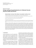
Fig. 1. Stress strain curves obtained for AZ31
gravity cast alloy at various temperatures in
tension.
Fig. 2. Stress strain curves obtained for AJ51
squeeze cast alloy at various temperatures in
compression.
Fig. 3. Stress strain curves obtained for ZK60
alloy deformed in compression at various
temperatures.
Fig. 4. Work hardening coefficient versus
stress obtained for AM20 alloy deformed in
tension at various temperatures.
The evolution equation describing the development of the dislocation structure with time or
strain can be generally described in the following form:
hr
dd d
dd d
ρ
ρρ
ε
εε
⎛⎞⎛⎞
=−
⎜⎟⎜⎟
⎝⎠⎝⎠
. (5)
The first (positive) term on the right hand accounts for the dislocation storage, while the
second one represents the annihilation of dislocations; it contributes to softening.
Model of Kocks
Kocks (Kocks, 1976) has assumed that the dislocation mean free path is proportional to the
average spacing between forest dislocations. He considered that an increase in the
dislocation density with strain is due to dislocation storage and a decrease in the dislocation
density is caused by annihilation of dislocations by cross slip.
Then, the evolution equation for the dislocation density reads:
Magnesium Alloys - Design, Processing and Properties
4
1/2
r
f
L
d
db
ρ
ρ
κρ
ε
=−, (6)
where L
r
is the average length of the dislocation segment recovered in one recovery event (due
to cross slip),
κ
f
is a geometrical factor based on the assumption that the mean free path
Λ
of
the dislocation glide is proportional to the average spacing between forest dislocations ℓ
d
i.e.
Λ = βℓ
d
= βρ
-1/2
. (7)
L
r
is a function of temperature and strain rate. The stress dependence of the strain hardening
rate of polycrystals (it is necessary to take into account the relationship between work
hardening coefficient (rate) of single crystals and polycrystals)
2
/ddM
σ
εθ
Θ= = , (σ =Mτ,
ε = γ/M , θ=dτ/dγ ).can be written.
0
1
K
SK
d
d
σσ
εσ
⎛⎞
Θ= =Θ −
⎜⎟
⎜⎟
⎝⎠
, (8)
where
2
1
0
2
f
K
M
Gb
α
κ
Θ=
and
2
1
f
SK
r
MGb
L
α
κ
σ
= .
In many cases, equation (8) cannot describe the whole work hardening curve that consists of
several regions with different slopes. This phenomenon is common for many materials. It
should be mentioned that texture influences the hardening parameters and therefore,
variation in M can be large (Cáceres & Lukáč, 2008).
Model of Estrin and Mecking
In contrary to the model of Kocks, Estrin and Mecking (Estrin & Mecking, 1984) have
assumed that the mean free path of dislocations Λ is constant and it is determined by the
spacing between impenetrable obstacles (grain boundaries, incoherent precipitates,
dispersion particles). Finally they obtained
1
r
L
d
dbsb
ρ
ρ
ε
=−
(9)
and
2
0
2
1
EM
SEM
σ
σ
σ
⎛⎞
Θ=Θ −
⎜⎟
⎜⎟
⎝⎠
, (10)
where
32
1
0
()
2
EM
M
Gb
sb
α
Θ= ,
()
1
1/2
SEM
r
M
Gb
sL
α
σ
= and s is the particle spacing or the grain size.
Model of Malygin
Malygin (Malygin, 1990) took into account: storage of dislocations on impenetrable
obstacles, storage of dislocations on forest dislocations and annihilation of dislocations due
to cross slip. The evolution equation has, in this case, the following form:
1/2
1
f
a
d
dbs
ρ
κ
ρκρ
ε
=+ −
, (11)
Hardening and Softening in Magnesium Alloys
5
where s is the particle spacing or the grain size, κ
f
is the coefficient of the dislocation
multiplication intensity due to interaction of moving dislocations with forest dislocations
and
κ
a
is the coefficient of the dislocation annihilation intensity due to cross slip. Finally, the
equation suitable for an analysis of the experimental strain hardening rate of polycrystals
is then
/dd
σ
ε
Θ
==A/ (σ - σ
y
) + B – C (σ - σ
y
). (12)
Here the following substitutions were made:
A
()
2
3
1
11
2
MGb
bs
α
=
; B
2
1
1
;
2
f
MGb
α
κ
=
and C
1
2
a
M
κ
=
.
The yield stress
σ
y
corresponds to the beginning of plastic deformation and comprises all
contributions from the various hardening mechanisms.
The model of Lukáč and Balík
In many cases, the Malygin model describes the whole work hardening curve at lower
temperatures where only stage II and III hardening occurs. At intermediate temperatures
(about 0.3 T
m
), there are deviations from the prediction of this model, which indicates the
presence of some other recovery process in addition to cross slip. Lukáč and Balík (Lukáč
&
Balík, 1994) assumed that hardening occurs due to multiplication of dislocations at both
non-dislocation obstacles and forest dislocations. As the dominant softening processes,
annihilation of dislocations due to both cross slip and climb are considered. They derived
the kinetic equation for single crystals in the following form:
2
1/2 3/2
1
CS c c
f
B
cL D b
d
dbs b kT
ψ
ρ
κρ τρ
γχγ
=+ − −
, (13)
where L
CS
is the dislocation segment length recovered by one cross slip event, c is the area
concentration of the recovery sites in a slip plane,
ψ
c
is a fraction of the dislocations which
can be annihilated by climb of dislocations with jogs,
χ
is a parameter which gives the
relation between dislocation climb distance w (i.e. distance between storage of a dislocation
and its annihilation site) and the average dislocation spacing
1/
ρ
in the form
/w
χ
ρ
= , τ is the shear stress, γ is the shear strain, k
B
is the Bolzmann constant and D
c
is
an abbreviation which includes the diffusion coefficient and the stacking fault energy. The
stress dependence of the work hardening rate for polycrystals reads:
(
)
(
)
3
/( )
yyy
ABCD
σσ σσ σσ
Θ= − + − − − − . (14)
Here the meaning of the parameters used is the following:
()
2
2
3
1
1
2
n
b
AM G
s
ε
α
ε
⎛⎞
=
⎜⎟
⎜⎟
⎝⎠
;
1
2
1
1
1
2
n
f
BMGn
ε
ακ
ε
⎛⎞
=
⎜⎟
⎜⎟
⎝⎠
;
2
CS
cL
CM
b
ρ
= ;
1
2
11
1
2
n
cc
B
Db
D
Gk T
M
ψ
ε
χα ε ε
−
⎛⎞
=
⎜⎟
⎜⎟
⎝⎠
Magnesium Alloys - Design, Processing and Properties
6
Here
1
ε
is a parameter and n is the stress exponent. It should be mention that, in the face-
centred-cubic metals, the parameters A and B are independent of temperature and the
parameters C and D depend on temperature.
Model of Estrin and Kubin.
In many cases, a model employing just one internal variable (the total dislocation density) is
not sufficient for describing deformation histories involving rapid changes of the
deformation path. Instead of using a single internal variable related to the total dislocation
density ρ, Estrin and Kubin (Estrin & Kubin, 1986) considered the density of mobile
dislocation ρ
m
and the relatively immobile dislocation density (or the forest dislocation
density) ρ
f
. The evolution equations for the two populations of dislocations proposed by
Estrin and Kubin can be expressed as
134
f
m
fm
m
d
kkk
d
ρ
ρ
ρρ
γ
ρ
=− − + (15)
123
f
ff
m
d
kkk
d
ρ
ρ
ρρ
γ
=−+. (16)
Here k
i
are constants. It can be seen that the negative terms in Eq. (15), which represent the
loss of the mobile dislocation density due to various dislocations reaction, reappear as
positive terms in eq. (16). Newly formulated two variable constitutive model was solved by
Estrin (Estrin, 1996) and Braasch, Estrin and Brechet (Braasch et al., 1996).
Model of Nes
Three parameters approach to the modelling of metal plasticity has been proposed by Nes &
Marthinsen (Nes & Marthinsen, 2002). It is assumed in the model that at small strains (stage
II) the stored dislocations are arranged in a cell structure which may be characterised by
thickness
t of cell walls; internal dislocation density
ρ
b
; dislocation density within cells. At
large strains (stage IV), the cell walls collapse into sub-boundaries with a misorientation ϕ.
The main features of the model can be summarised as follows:
1. The flow stress
τ
is done by
12
/
ii
Gb Gb
τ
τα ρα δ
=+ + , (17)
where
τ
I
is the frictional stress, α
1
and α
2
are constants, and δ is the size of cells or subgrains.
The frictional stress reflects short range interactions associated with the intersection of forest
dislocations and dragging of jogs which can be expressed by
()
1
2
2sinh exp
ia i
miD
BB
VU
bC
kT kT
τ
ρν γ
−
⎛⎞
=
⎜⎟
⎜⎟
⎝⎠
, (18)
where V
a
is the activation volume, U
i
is the activation energy, ρ
m
is the mobile dislocation
density
ν
D
the Debye frequency and C
i
is a constant; k
B
T has its usual meaning.
2. Dislocations are stored during deformation in three sites: in the cell interior, in old
boundaries and/or by forming new boundaries. These processes can be described by the
following equation
Hardening and Softening in Magnesium Alloys
7
2
nb
i
d
L
S
db
ρ
ρ
γ
+
=
, (19)
where
ρ
nb
are dislocations stored in new boundaries, L is the mean free path of dislocations
before being stored, L=C
ρ
-1/2
(C is a constant), ρ is the total density of stored dislocations. S
is dislocation storage parameter that can be defined using microstructural scaling C
i
constants and volume fraction of cell walls f: S=S
sc
=S
sc
(f, C
c
, C
t
, C
cb
), where C
c
=δρ
i
1/2
, C
t
=t/δ
and C
cb
=δρ
b
1/2
. Equation (19) can be expressed in the following alternative forms:
Stage II:
()
1/2
1/2
2
2
1/
ii
bc
d
d
bC f C C
ρ
ρ
γ
+
=−
⎡⎤
−+
⎢⎥
⎣⎦
Stage III and IV:
()
2
1/2
2
/
III
III
dSC
d
b
δρδ
γ
κϕ ρ κϕ δ
−
=−
+
where C
b
=fC
cb
and κ is a geometric constant that is equal to 2 for a regular cell structure.
Based on experimental observations the sub-boundary orientation,
ϕ, depends on δ in stage
III and becomes a constant in stage IV, while S is treated as a modelling parameter.
3. Dynamic recovery is incorporated assuming two mechanisms: a) a dislocation segment in
a Frank network which may migrate under a force per unit length, F, with a velocity
2
1/2
exp 2sinh
D
B
U
Fb
bC
kT k T
ρ
ρ
υυ
⎛⎞
=−
⎜⎟
⎝⎠
,
where
21/2
3
i
FGb
ρ
αξ ρ
= , C
ρ
and α
3
are constants, U
ρ
is the activation energy and ξ
ρ
a
dynamic stress intensity factor. The average subgrain size will increase according to
1/2
exp 2sinh
a
D
BB
p
V
U
dd
bC
dt dt k T k T
δ
δ
δδ
γυρ
++
⎛⎞
== −
⎜⎟
⎜⎟
⎝⎠
,
where V
a
is the activation volume. It should be mentioned that the models mentioned above
were developed for polycrystals of face-centred-cubic metals that have more than 5
independent slip systems. On the other hand, hexagonal metals with the low symmetry do
not provide 5 identical slip systems. To fulfil the von Mises criterion for polycrystal
deformation, several different crystallographic slip systems have to be activated.
In magnesium and its alloys, the dominant slip mode is the basal slip with two independent
modes, which is not sufficient for the satisfying the von Mises criterion. The glide of
dislocation in second-order pyramidal slip systems should be considered.
Comparison with experimental results
Comparing experimental stress strain curves (for example curves introduced in Figs. 1-3)
with the models of the strain hardening, the best agreement for hexagonal magnesium
alloys was found for the Lukáč and Balík model (L-B model). Corresponding stress
dependences of the work hardening coefficients are introduced in Fig. 4. From Fig. 4 it can
be easily seen that the work hardening coefficient
Θ does not decreases with the increasing
stress linearly; then the Kocks model may not work. Note that the Nes model was not
analysed because of missing dislocation substructure data. Parameters following from the L-
B model are introduced in Table 1 (Máthis
& Trojanová, 2005).
Magnesium Alloys - Design, Processing and Properties
8
A (MPa
2
) B (MPa) C
D x 10
4
(MPa
-2
)
R
2
σ
y
(MPa)
σ
02
(exp)
(MPa)
0.2%Zn
820
± 178
2010
± 20
5.4
± 0.3
2.77
± 0.07
0.987
57.40
± 0.10
59
0.3%Zn
930
± 60
1750
± 10
0.5
± 0.2
4.97
± 0.05
0.988
71.48
± 0.07
71
0.4%Zn
1940
± 160
1910
± 20
4.2
± 0.3
2.30
± 0.04
0.986
65.76
± 0.04
70
1%Zn
1870
± 170
1780
± 20
2.7
± 0.3
1.65
± 0.06
0.97
87.28
± 0.06
86
2%Zn
11100
± 600
1780
± 30
1.6
± 0.3
1.00
± 0.04
0.984
97.80
± 0.20
100
3%Zn
46000
± 6000
1360
± 190
3e-3
± 1.7
1.17
± 0.28
0.988
114.70
± 0.10
109
Table 1. Concentration dependence of the parameters of best fit for the L-B model and the
calculated and measured yield stress for Mg-Zn alloys.
A (MPa
2
) B (MPa) C
D x 10
4
(MPa
-2
)
R
2
σ
y
(MPa)
σ
02
(exp)
(MPa)
20 °C
68.700 ±
400
1532 ±
12
0 3.5 ± 0.6 0.99 78.3 ± 0.2 79
50 °C
49.200 ±
600
1471 ±
23
0 2.5 ± 0.7 0.99 61.2 ± 0.2 68
100 °C
54.800 ±
400
846 ± 15 0 4.4 ± 0.1 0.99 67.0 ± 0.7 69
150 °C
29.000 ±
100
346 ± 29 0 9.3 ± 0.1 0.99 67.0 ± 0.3 65
200 °C
4.173 ± 896 691 ± 52
14.1 ±
0.6
6.0 ± 0.3 0.97 64.2 ± 0.2 64
Table 2. Temperature dependence of the parameters of best fit to L-B-model and the
calculated and measured yield stress for Mg alloy AM60.
The parameter A increases monotonically with the increasing solute content for Mg-Zn
alloys in agreement with the prediction of the model, i.e. the parameter A is reciprocally
proportional to the distance of impenetrable obstacles. The results suggest the increasing
role of non-dislocation obstacles (e.g. solute atoms, clusters, precipitates, dispersoids) in the
hardening mechanism. The parameter B
remains nearly constant for all concentrations.
Since this parameter is connected with the dislocation – forest dislocation interaction, this
result indicates that the dislocation density in non-basal slip systems does not change with
increasing solute content. There is a significant difference in parameter C, which
characterizes the cross slip of screw dislocations. Cross slip takes place through prismatic
slip system, and an increased activity of this slip system could enhance the ductility. In the
case of Mg-Zn alloys, values of parameter C are of the order assumed by the model and
Hardening and Softening in Magnesium Alloys
9
suggest the importance of cross slip in the deformation process. The concentration
dependencies of this parameter (see Table 1) and ductility are in agreement, i.e. decrease
with increasing concentration of Zn, thus the probability of cross slip decreases as well. It
seems that 2 at.% Zn is a critical concentration; above that Zn content ceases improving the
slip in prismatic slip system. It is necessary to remark that the model is able to describe drop
in ductility for 0.3 at.% Zn, where the value of parameter C is small. This result supports the
hypothesis of Akthar and Tegthsoonian (Akthar
& Tegthsoonian, 1972), who assumed a
hardening in prismatic plane for this concentration of Zn. Decreasing of
parameter D with
increasing solute content is most probably connected with reduced climb ability because of
the high concentration of solute atoms along the dislocation line, and due to the lowering of
the stacking fault energy as the solute content increases. Lowering of stacking fault energy
improves the twinning activity as well. Note that the twin boundaries may be the
impenetrable obstacles for dislocation motion. In materials with the strong texture (rolled
sheets) when twinning is unfavourable it is necessary to consider the evolution of the
dislocation substructure in both basal and non-basal slip systems, as it was shown by Balík
et al. (Balík et al., 2009).
Similar analysis according to L-B model was performed for magnesium alloy AM60
deformed at various temperatures by Máthis et al. (Máthis et al., 2004a) Results are
introduced in Table 2. The parameter A is not expected to depend on temperature, while
Table 2 shows that the value of A drops rapidly above 150 °C. Alloy AM60 contains about
4% volume fraction of the intermetallic phase Mg
17
Al
12
, which is likely to dissolve as the
temperature is increased. This will result in increased spacing between non-dislocations
obstacles, which, in turn, would lower the value of the parameter A. Similarly, a decrease in
the forest dislocation density (the density of dislocations in non-basal planes) can be
expected at increasing temperatures. The mean free path of dislocations and therefore the
storage distance will increase. The storage probability should decrease. This could cause the
temperature decrease in the parameter B. The parameter C
becomes >0 at 200 °C, which
indicates that the cross slip becomes a significant recovery process at higher temperatures.
The parameter D
increases with increasing temperature, which is expected in the case of
climb. Above 250 °C the model does not describe the experimental curves satisfactory; we
suggest that another softening mechanism, most likely dynamic recrystallisation, may
become operative.
4. Internal stress in magnesium alloys
In the stress relaxation tests, specimen is deformed to a certain stress (strain) and then
allowed to relax by stopping the machine. Stress relaxation (SR) is usually analysed under
an assumption that the strain rate during the SR experiments is proportional to the stress
rate (the stress drops in one second). Components of the applied stress (
σ
i
, σ
∗
) can be
estimated using Li’s method (Li, 1967, 1981). The SR curves were fitted to a power law
function in the form:
()
()
1
1
1
1
i0
1
m
m
am t t
σσ
−
−
⎡⎤
−= − +
⎣⎦
, (20)
where a, t
0,
and m are fitting parameters.
Magnesium Alloys - Design, Processing and Properties
10
A part of the AX41 true stress − true strain curve measured in compression at 25 ºC with
points indicating the stresses at which the SR tests were performed is shown in Fig. 5. Open
circles and full circles depict the internal stress σ
i,
and the effective stress σ
*
, respectively. It
is obvious that the internal stress
σ
i
is a substantial contribution to the applied stress σ
ap
.
Similar curves estimated at 150 °C are shown in Fig. 6. The effective stress component
increases with increasing strain while the internal stress increases to the maximum and then
decreases with increasing strain. Fig. 7 shows the curves obtained at 300 °C. The internal
stress is lower than the effective stress and it decreases for strains higher than
ε
= 0.02. The
internal stress depends on the dislocation density, i.e.
σ
i
∝ ρ
1/2
. A decrease of the internal
stress indicates a decrease of the dislocation density. In the case when the internal stress is
approximately constant or slightly decreasing with strain, some equilibrium between
multiplication and annihilation of dislocations may be considered.
AX41 25°C
ε
0.00 0.04 0.08 0.12 0.16
σ (MPa)
0
100
200
300
compression
σ
ap
σ
i
σ
*
AX41 150°C
ε
0.00 0.04 0.08 0.12 0.16
σ (MPa)
0
50
100
150
200
250
300
compression
σ
ap
σ
i
σ
*
Fig. 5. A part of the true stress
−true strain
curve obtained for the AX41 alloy at 25 ºC in
compression. The points of
σ
ap
on the curve
indicate the stresses at which the SR tests
were performed.
Fig. 6. A part of the true stress-true strain
curve obtained for the AX41 alloy at 150 ºC in
compression. The points of
σ
ap
on the curve
indicate the stresses at which the SR tests
were performed.
AX41 300°C
ε
0.00 0.04 0.08 0.12 0.16
σ
(MPa)
0
20
40
60
80
100
σ
i
σ
*
σ
ap
compression
AJ91
temperature (°C)
0 50 100 150 200 250 300
σ
i
/σ
ap
0.4
0.6
0.8
1.0
1.2
tension
compression
σ
i
=
σ
ap
Fig. 7. Part of the stress
− strain curve for
AX41 alloy at 300 ºC. The points of
σ
ap
on the
curve indicate the stresses at which the SR
tests were performed.
Fig. 8. Variation of the internal/applied stress
ratio obtained from the first SR test with
temperature estimated for the AJ91 samples.
Hardening and Softening in Magnesium Alloys
11
The moving dislocations can cross slip and after cross slip they may annihilate, which
causes the decrease in the dislocation density. At higher temperatures, the moving
dislocations can also climb. The activity of cross slip and climb increases with increasing
temperature. This means that the total dislocation density decreases with increasing
temperature. The internal stress/applied stress ratio decreases significantly with increasing
temperature independent of the deformation mode (the values of the ratio for compression
deformation are practically the same as for tension) (see Fig. 8 where the temperature
dependence of
σ
i
/σ
ap
is introduced for AJ91 alloy). It is possible to estimate the internal
stress also in creep experiments as it was performed by Milička et al. (Milička et al., 2007) for
several magnesium alloys. They found that the internal stress
σ
i
reflects the creep resistance
of the material. Experimental internal stresses determined in creep well correspond to those
determined in SR tests under comparable testing conditions.
5. Thermally activated dislocation motion
The deformation behaviour of materials depends on temperature and strain rate. Practically
in all polycrystals, the temperature and strain rate dependences of the flow stresses can be
found. These dependences indicate thermally activated processes. The motion of
dislocations through a crystal is affected by many kinds of obstacles. The mean velocity of
dislocations is connected with the strain rate by the Orowan equation
(
)
1/
m
M
bv
ε
ρ
=
(21)
where
ρ
m
is the density of mobile dislocations moving at a mean velocity ν. It is obvious that
the stress dependence of
ε
is done by the stress dependence of
ρ
and v. At a finite
temperature, the obstacles can be overcome with the help of thermal fluctuations. Therefore,
the dislocations are able to move even if the force on dislocations is lower than that exerted
by the obstacles; the additional energy is supplied by thermal fluctuations. The short-range
thermally activated processes are important for the understanding of deformation
behaviour. If a single process is controlling the rate of dislocation glide, the plastic strain
rate
ε
can be expressed as:
*
0
()
exp
B
G
kT
σ
εε
⎡
⎤
Δ
=−
⎢
⎥
⎢
⎥
⎣
⎦
, (22)
where
ε
0
is a pre-exponential factor containing the mobile dislocation density, the average
area covered by the dislocations in every activation act, the Burgers vector, the vibration
frequency of the average dislocation segment and a geometric factor.
ΔG(σ
*
) is the change in
the Gibbs free enthalpy depending on the effective stress
σ
*
=σ-σ
i
, T is the absolute
temperature and k
B
is the Boltzmann constant. The stress dependence of the free enthalpy
may be expressed by a simple relation
ΔG(σ*) = ΔG
0
- Vσ
*
= ΔG
0
– V(σ – σ
i
), (23)
where
ΔG
0
is the Gibbs free enthalpy necessary for overcoming a short-range obstacle
without the stress and V = bdL is the activation volume where d is the obstacle width and L
is the mean length of dislocation segments between obstacles. It should be mentioned that L
may depend on the stress acting on dislocation segments.
Magnesium Alloys - Design, Processing and Properties
12
The nature and the distribution of obstacles determine the activation parameters (the
activation energy and the activation volume). For a given arrangement of obstacles in a
material, the thermally activated process controls the temperature and strain rate dependence
of the flow stress. Two methods are very often used for the estimation of the activation
volume: differential constant strain rate tests and stress relaxation experiments. In differential
constant strain rate tests, the specimen is deformed with a constant strain rate to a given strain
(stress) and then the strain rate is suddenly changed by a known factor. The resulting change
in stress is observed; an increase (decrease) in the stress is observed if the strain rate increases
(decreases). The activation volume is inversely proportional to this stress change. The
activation volume can be estimated from the stress relaxation tests. The stress decrease with
time during the SR test can be described by the known Feltham equation (Feltham, 1963)
Δσ(t) = σ(0) − σ(t) = αln(βt + 1) , (24)
where
σ(0) is the stress at the beginning of the stress relaxation at time t = 0, β is a constant.
The activation volume is done by:
B
kT
V
α
=
. (25)
and the constant β
*
00
(0)
(0)
exp
BB
MV G V
M
kT kT
εσ
ε
β
α
⎡⎤
Δ−
=− =
⎢⎥
⎢⎥
⎣⎦
. (26)
Values of the apparent activation volume estimated using Eq. (24) are plotted against the
applied stress in Fig. 9 for AJ51 and in Fig. 10 for AZ63 alloys for several deformation
temperatures. The activation volume depends on the applied stress and testing temperature.
Apparent (experimental) activation volume estimated in experiments with polycrystals is
proportional to the dislocation activation volume, V
d,
as V = (1/M)V
d
. Usually, the values of
activation volume are given in b
3
, which allows their comparison with processes responsible
for the thermally activated dislocation motion. Apparent activation volumes for AJ51 alloy
estimated for four deformation temperatures in tensile (T) and compression (C) tests are
plotted against the effective (thermal) stress in Fig. 11. All values appear to lie on one line,
“master curve”. Similar results were found for other magnesium alloys among them also for
AZ63 alloy (see Fig. 12).
In order to analyse the dependences, we will assume an empirical relation between the
Gibbs free enthalpy Δ G and the effective stress, σ
*
, suggested by Kocks and co-workers
(Kocks et al., 1975) in the following form:
0
0
1
q
p
GG
σ
σ
∗
∗
⎡
⎤
⎛⎞
⎢
⎥
Δ=Δ −
⎜⎟
⎜⎟
⎢
⎥
⎝⎠
⎣
⎦
(27)
where
0
σ
∗
is the effective stress at 0 K. From (22) and (27) it follows:
1/
1/
0
0
0
1ln
p
q
B
kT
G
ε
σσ
ε
∗∗
⎡
⎤
⎛⎞
⎢
⎥
=−
⎜⎟
⎜⎟
⎢
⎥
Δ
⎝⎠
⎣
⎦
, (28)
Hardening and Softening in Magnesium Alloys
13
AJ51
compression
applied stress σ
ap
(MPa)
50 100 150 200 250 300 350
V/b
3
0
20
40
60
80
100
120
140
25°C
100°C
200°C
applied stress σ
ap
(MPa)
80 120 160 200 240 280 320
V/b
3
0
50
100
150
200
250
25°C
100°C
150°C
200°C
compression
AZ63
Fig. 9. Plot of the apparent activation volume
(in b
3
) against the applied stress σ
ap
estimated
for the AJ51 alloy in compression, at three
temperatures.
Fig. 10. Plot of the apparent activation
volume (in b
3
) against the applied stress σ
ap
estimated for four deformation
temperatures in compression.
AJ51
σ* (MPa)
0 20 40 60 80 100 120
V/b
3
0
50
100
150
200
250
T 25°C
T 100°C
T 150°C
T 200°C
C 25°C
C 100°C
C 200°C
σ* (MPa)
0 20406080100
V/b
3
0
50
100
150
200
250
300
25°C
50°C
100°C
150°C
200°C
300°C
AZ63
Fig. 11. Plot of the apparent activation volume
(in b
3
) against the thermal stress σ* estimated
for four deformation temperatures in tension
(T) and compression (C) for the AJ51 alloy.
Fig. 12. Plot of the apparent activation
volume (in b
3
) against the thermal stress σ*
estimated for various deformation
temperatures (AZ63 alloy).
where p and q in Eqs. (27) and (28) are phenomenological parameters reflecting the shape of
a obstacle profile. The possible ranges of values p and q are limited by the conditions 0
< p ≤
1 and 1
≤ q ≤ 2. Ono (Ono, 1968) and Kappor and co-workers (Kapoor et al., 2002) suggested
that Eq. (28) with p = 1/2, q = 3/2 describes a barrier shape profile that fits many predicted
barrier shapes. Equation (28) can be rewritten as
0
0
0
exp 1
q
p
B
G
kT
σ
εε
σ
∗
∗
⎡
⎤
⎛⎞
⎛⎞
Δ
⎢
⎥
⎜⎟
=−−
⎜⎟
⎢
⎥
⎜⎟
⎜⎟
⎝⎠
⎢
⎥
⎝⎠
⎣
⎦
. (29)
The dependence of the activation volume on the effective stress can be expressed as