NUCLEAR REACTORS potx
Bạn đang xem bản rút gọn của tài liệu. Xem và tải ngay bản đầy đủ của tài liệu tại đây (16.75 MB, 350 trang )
NUCLEAR REACTORS
Edited by Amir Zacarias Mesquita
Nuclear Reactors
Edited by Amir Zacarias Mesquita
Published by InTech
Janeza Trdine 9, 51000 Rijeka, Croatia
Copyright © 2012 InTech
All chapters are Open Access distributed under the Creative Commons Attribution 3.0
license, which allows users to download, copy and build upon published articles even for
commercial purposes, as long as the author and publisher are properly credited, which
ensures maximum dissemination and a wider impact of our publications. After this work
has been published by InTech, authors have the right to republish it, in whole or part, in
any publication of which they are the author, and to make other personal use of the
work. Any republication, referencing or personal use of the work must explicitly identify
the original source.
As for readers, this license allows users to download, copy and build upon published
chapters even for commercial purposes, as long as the author and publisher are properly
credited, which ensures maximum dissemination and a wider impact of our publications.
Notice
Statements and opinions expressed in the chapters are these of the individual contributors
and not necessarily those of the editors or publisher. No responsibility is accepted for the
accuracy of information contained in the published chapters. The publisher assumes no
responsibility for any damage or injury to persons or property arising out of the use of any
materials, instructions, methods or ideas contained in the book.
Publishing Process Manager Iva Simcic
Technical Editor Teodora Smiljanic
Cover Designer InTech Design Team
First published February, 2012
Printed in Croatia
A free online edition of this book is available at www.intechopen.com
Additional hard copies can be obtained from
Nuclear Reactors, Edited by Amir Zacarias Mesquita
p. cm.
ISBN 978-953-51-0018-8
Contents
Preface IX
Chapter 1 Experimental Investigation of
Thermal Hydraulics in the IPR-R1 TRIGA Nuclear Reactor 1
Amir Zacarias Mesquita, Daniel Artur P. Palma,
Antonella Lombardi Costa, Cláubia Pereira,
Maria Auxiliadora F. Veloso
and Patrícia Amélia L. Reis
Chapter 2 Flow Instability in Material Testing Reactors 25
Salah El-Din El-Morshedy
Chapter 3 Herium-Air Exchange Flow Rate Measurement
Through a Narrow Flow Path 47
Motoo Fumizawa
Chapter 4 New Coolant from Lead Enriched with the Isotope
Lead-208 and Possibility of Its Acquisition from
Thorium Ores and Minerals for Nuclear Energy Needs 57
Georgy L. Khorasanov, Anatoly I. Blokhin and Anton A. Valter
Chapter 5 Decay Heat and Nuclear Data 71
A. Algora and J. L. Tain
Chapter 6 Transport of Interfacial Area
Concentration in Two-Phase Flow 87
Isao Kataoka, Kenji Yoshida, Masanori Naitoh,
Hidetoshi Okada and Tadashi Morii
Chapter 7 Thermal Aspects of Conventional
and Alternative Fuels in SuperCritical
Water-Cooled Reactor (SCWR) Applications 123
Wargha Peiman, Igor Pioro and Kamiel Gabriel
Chapter 8 Development of an Analytical Method
on Water-Vapor Boiling Two-Phase Flow Characteristics
in BWR Fuel Assemblies Under Earthquake Condition 157
Takeharu Misawa, Hiroyuki Yoshida and Kazuyuki Takase
VI Contents
Chapter 9 The Theoretical Simulation of a Model by
SIMULINK for Surveying the Work and
Dynamical Stability of Nuclear Reactors Cores 175
Seyed Alireza Mousavi Shirazi
Chapter 10 Theory of Fuel Life Control Methods at
Nuclear Power Plants (NPP) with
Water-Water Energetic Reactor (WWER) 197
Sergey Pelykh and Maksim Maksimov
Chapter 11 Improving the Performance
of the Power Monitoring Channel 231
M. Hashemi-Tilehnoee and F. Javidkia
Chapter 12 Multiscale Materials Modeling of Structural
Materials for Next Generation Nuclear Reactors 259
Chaitanya Deo
Chapter 13 Application of Finite Symmetry Groups
to Reactor Calculations 285
Yuri Orechwa and Mihály Makai
Chapter 14 Neutron Shielding Properties
of Some Vermiculite-Loaded New Samples 313
Turgay Korkut, Fuat Köksal and Osman Gencel
Chapter 15 Development of
99
Mo Production Technology
with Solution Irradiation Method 323
Yoshitomo Inaba
Preface
Rising concerns about global warming, supply security, and depleting fossil fuel
reserves have spurred a revival of interest in nuclear power generation, giving birth to
a “nuclear power renaissance” in countries the world over. As humankind seeks
abundant and environmentally responsible energy in the coming decades, the
renaissance of nuclear power will undoubtedly become reality as it is a proven
technology and has the potential to generate virtually limitless energy with no
greenhouse gas emissions during operations. According to the International Atomic
Energy Agency the number of nuclear power reactors in operation worldwide in 2011
is 433 units, and 65 under construction. A large-scale period of nuclear power plants
construction would allow nuclear energy to contribute substantially to the
decarbonisation of electricity generation. In addition, basic research and nuclear
technology applications in chemistry, physics, biology, agriculture, health and
engineering have been showing their importance in the innovation of nuclear
technology applications with sustainability.
The renaissance of nuclear power has been threatened by the catastrophe in Japan and
the atomic industry faces the challenge of assuring a skeptical public that new reactors
are safer than the old ones and nearly disaster-proof. The disaster at the Fukushima
Daiichi nuclear plant in Japan demonstrates that older nuclear reactor technology
requires strict adherence to quality assurance practices and procedures. Newer nuclear
reactor designs promote the use of passive cooling systems that would not fail after
power outages, as well as other innovative approaches to managing reactor heat. New
reactors use the same principle of power generation as in older water reactors such as
the ones at Fukushima: nuclear reactors heat water to create steam that turns turbines
to generate electricity. However, technological advances have improved efficiency and
stricter safety precautions have made the third-generation reactors more secure. The
new generation of pressurized water reactor plants has diesel-powered backup
systems that are housed in separate buildings to protect them from any accident that
might occur in the main reactor building. The plant must also have access to other
sources of electricity if the diesel generators fail.
This book is targeted at nuclear regulatory authorities, environmental and energy
scientists, students, researchers, engineers, seismologists and consultants. It presents a
comprehensive review of studies in nuclear reactors technology from authors across
X Preface
the globe. Topics discussed in this compilation include: thermal hydraulic
investigation of TRIGA type research reactor, materials testing reactor and high
temperature gas-cooled reactor; the use of radiogenic lead recovered from ores as a
coolant for fast reactors; decay heat in reactors and spent-fuel pools; present status of
two-phase flow studies in reactor components; thermal aspects of conventional and
alternative fuels in supercritical water‒cooled reactor; two-phase flow coolant
behavior in boiling water reactors under earthquake condition; simulation of nuclear
reactors core; fuel life control in light-water reactors; methods for monitoring and
controlling power in nuclear reactors; structural materials modeling for the next
generation of nuclear reactors; application of the results of finite group theory in
reactor physics; and the usability of vermiculite as a shield for nuclear reactor.
Concluding the book is presented a review of the use of neutron flux in the
radioisotopes production for medicine.
Amir Zacarias Mesquita, ScD.
Researcher of
Nuclear Technology Development Center (CDTN)
Brazilian Nuclear Energy Commission (CNEN)
Belo Horizonte - Brazil
1
Experimental Investigation of
Thermal Hydraulics in the IPR-R1 TRIGA
Nuclear Reactor
Amir Zacarias Mesquita
1
, Daniel Artur P. Palma
2
,
Antonella Lombardi Costa
3
, Cláubia Pereira
3
,
Maria Auxiliadora F. Veloso
3
and Patrícia Amélia L. Reis
3
1
Centro de Desenvolvimento da Tecnologia Nuclear/Comissão Nacional de Energia Nuclear
2
Comissão Nacional de Energia Nuclear
3
Departamento de Engenharia Nuclear –Universidade Federal de Minas Gerais
Brazil
1. Introduction
Rising concerns about global warming and energy security have spurred a revival of interest
in nuclear energy, leading to a “nuclear power renaissance” in countries the world over. In
Brazil, the nuclear renaissance can be seen in the completion of construction of its third
nuclear power plant and in the government's decision to design and build the Brazilian
Multipurpose research Reactor (RMB). The role of nuclear energy in Brazil is
complementary to others sources. Presently two Nuclear Power Plants are in operation
(Angra 1 and 2) with a total of 2000 MW
e
that accounts for the generation of approximately
3% of electric power consumed in Brazil. A third unity (Angra 3) is under construction.
Even though with such relatively small nuclear park, Brazil has one of the biggest world
nuclear resources, being the sixth natural uranium resource in the world and has a fuel cycle
industry capable to provide fuel elements. Brazil has four research reactors in operation: the
MB-01, a 0.1 kW critical facility; the IEA-R1, a 5 MW pool type reactor; the Argonauta, a 500
W Argonaut type reactor and the IPR-R1, a 100 kW TRIGA Mark I type reactor. They were
constructed mainly for using in education, radioisotope production and nuclear research.
Understanding the behavior of the operational parameters of nuclear reactors allow the
development of improved analytical models to predict the fuel temperature, and
contributing to their safety. The recent natural disaster that caused damage in four reactors
at the Fukushima nuclear power plant shows the importance of studies and experiments on
natural convection to remove heat from the residual remaining after the shutdown.
Experiments, developments and innovations used for research reactors can be later applied
to larger power reactors. Their relatively low cost allows research reactors to provide an
excellent testing ground for the reactors of tomorrow.
The IPR-R1 TRIGA Mark-I research reactor is located at the Nuclear Technology
Development Centre - CDTN (Belo Horizonte/Brazil), a research institute of the Brazilian
Nuclear Energy Commission - CNEN. The IPR-R1 reached its first criticality on November
Nuclear Reactors
2
1960 with a core configuration containing 56 aluminum clad standard TRIGA fuel elements,
and a maximum thermal power of 30 kW. In order to upgrade the IPR-R1 reactor power,
nine stainless steel clad fuel elements were purchased in 1971. One of these fuel elements
was instrumented in the centreline with three type K thermocouples. On December 2000,
four of these stainless steel clad fuel elements were placed into the core allowing to
upgrading the nominal power to 250 kW. In 2004 the instrumented fuel element (IF) was
inserted into all core rings and monitored the fuel temperature, allowing heat transfer
investigations at several operating powers, including the maximum power of 250 kW
(Mesquita, 2005). The basic safety limit for the TRIGA reactor system is the fuel temperature,
both in steady-state and pulse mode operation. The time-dependence of temperature was
not considered here, hence only the steady-state temperature profile was studied.
This chapter presents the experiments performed in the IPR-R1 reactor for monitoring some
thermal hydraulic parameters in the fuel, pool and core coolant channels. The fuel
temperature as a function of reactor power was monitored in all core rings. The radial and
axial temperature profile, coolant velocity, mass flow rate and Reynolds’s number in coolant
channels were monitored in all core channels. It also presents a prediction for the critical
heat flux (CHF) in the fuel surface at hot channel. Data from the instrumented fuel element,
pool, and bulk coolant temperature distribution were compared with the theoretical model
and results from other TRIGA reactors. A data acquisition system was developed to provide
a friendly interface for monitoring all operational parameters. The system performs the
temperature compensation for the thermocouples. Information displayed in real-time was
recorded on hard disk in a historical database (Mesquita & Souza, 2008). The data obtained
during the experiments provide an excellent picture of the IPR-R1 reactor’s thermal
performance. The experiments confirm the efficiency of natural circulation in removing the
heat produced in the reactor core by nuclear fission (Mesquita & Rezende, 2010).
2. The IPR-R1 reactor
The IPR-R1 TRIGA (Instituto de Pesquisas Radiativas - Reactor 1, Training Research Isotope
production, General Atomic) is a typical TRIGA Mark I light-water and open pool type
reactor. The fuel elements in the reactor core are cooled by water natural circulation. The
basic parameter which allows TRIGA reactors to operate safely during either steady-state or
transient conditions is the prompt negative temperature coefficient associated with the
TRIGA fuel and core design. This temperature coefficient allows great freedom in steady
state and transient operations. TRIGA reactors are the most widely used research reactor in
the world. There is an installed base of over sixty-five facilities in twenty-four countries on
five continents. General Atomics (GA), the supplier of TRIGA research reactors, since late
50’s continues to design and install TRIGA reactors around the world, and has built TRIGA
reactors in a variety of configurations and capabilities, with steady state thermal power
levels ranging from 100 kW to 16 MW. TRIGA reactors are used in many diverse
applications, including production of radioisotopes for medicine and industry, treatment of
tumors, nondestructive testing, basic research on the properties of matter, and for education
and training. The TRIGA reactor is the only nuclear reactor in this category that offers true
"inherent safety", rather than relying on "engineered safety". It is possible due to the unique
properties of GA's uranium-zirconium hydride fuel, which provides incomparable safety
characteristics, which also permit flexibility in sitting, with minimal environmental effects
Experimental Investigation of Thermal Hydraulics in the IPR-R1 TRIGA Nuclear Reactor
3
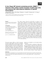
(General Atomics, 2011). Figure 1 shows two photographs of the pool and the core with the
IPR-R1 TRIGA reactor in operation.
Fig. 1. IPR-R1 TRIGA reactor pool and core
The IPR-R1 TRIGA reactor core is placed at the bottom of an open tank of about 6m height
and 2m diameter. The tank is filled with approximately 18 m
2
of water able to assure an
adequate radioactive shielding, as shown in Fig. 2. The reactor is licensed to operate at a
maximum steady-state thermal power level of 100 kW, but the core and the instrumentation
are configured to 250 kW, and waiting the definitive license to operate in this new power.
Some of the experiments reported here were performed at power operation of 250 kW. For
these experiments was obtained a provisional license for operation to this new power.
The reactor core is cooled by water natural circulation. Cooling water passage through the
top plate is provided by the differential area between a triangular spacer block on top of fuel
element and the round hole in the grid. A heat removal system is provided for removing
heat from the reactor pool water. The water is pumped through a heat exchanger, where the
Nuclear Reactors
4
heat is transferred from the primary to the secondary loop. The secondary loop water is
cooled in an external cooling tower. Figure 3 shows the forced cooling system, which
transfers the heat generated in the reactor core to a water-to-water heat exchanger. The
secondary cooling system transfers the reactor core heat from the heat exchanger to a
cooling tower. In the diagram is shown also the instrumentation distribution and the forced
and natural circulation paths in the pool.
Fig. 2. IPR-R1 TRIGA reactor pool and core
A simplified view of the IPR R1 TRIGA core configuration is shown in the Fig. 4. As shown
in the diagram there are small holes in the core upper grid plate. These holes were used to
insert thermocouples to monitor the coolant channel temperatures. The core has a
cylindrical configuration of six rings (A, B, C, D, E and F) having 1, 6, 12, 18, 24 and 30
locations respectively. These 91 positions are able to host either fuel rods or other
components like control rods, a neutron source, graphite dummies (mobile reflector),
irradiating and measurement channels (e.g. central thimble or A ring). Each location
corresponds to a role in the aluminum upper grid plate of the reactor core. The core is
surrounded by an annular graphite reflector and water. Inside the reflector there is a rotary
specimen rack with 40 positions for placement of samples to be activated by neutron flux.
The top view of the reactor core and the rotary specimen rack are presented in Fig. 5. There
is a very high number of reactor loading configurations, so that it is possible to obtain the
sub-critical level required simply loading/unloading fuel rods from the core.
Experimental Investigation of Thermal Hydraulics in the IPR-R1 TRIGA Nuclear Reactor
5
Fig. 3. IPR-R1 TRIGA reactor cooling system and instrumentation distribution
Fig. 4. Simplified core diagram
The prototypical cylindrical fuel elements are a homogeneous alloy of zirconium hydride
(neutron moderator) and uranium enriched at 20% in
235
U. The reactor core has 58
Nuclear Reactors
6
aluminum-clad fuel elements and 5 stainless steel-clad fuel elements. One of these steel-clad
fuel elements is instrumented with three thermocouples along its centreline, and was
inserted in the reactor core in order to evaluate the thermal hydraulic performance of the
IPR-R1 reactor (Mesquita, 2005). The fuel rod has about 3.5 cm diameter, the active length is
about 37 cm closed by graphite slugs at the top and bottom ends which act as axial reflector.
The moderating effects are carried out mainly by the zirconium hydride in the mixture, and
on a smaller scale by light water coolant. The characteristic of the fuel elements gives a very
high negative prompt temperature coefficient, is the main reason of the high inherent safety
behavior of the TRIGA reactors. The power level of the reactor is controlled with three
independent control rods: a Regulating rod, a Shim rod, and a Safety rod.
Fig. 5. Core configuration with the rotary specimen rack
Experimental Investigation of Thermal Hydraulics in the IPR-R1 TRIGA Nuclear Reactor
7
3. Methodology
3.1 Fuel and core coolant channel temperatures
Before starting the experiments the thermal power released by the core was calibrated,
according with the methodology developed by Mesquita et al. (2007). The calibration
method used consisted of the steady-state energy balance of the primary cooling loop. For
this balance, the inlet and outlet temperatures and the water flow in this primary cooling
loop were measured. The heat transferred through the primary loop was added to the heat
leakage from the reactor pool. The temperature measurements lines were calibrated as a
whole, including sensors, cables, data acquisition cards and computer. The uncertainties for
the temperature measurement circuit were ±0.4
o
C for resistance temperature detectors, and
±1.0
o
C for thermocouples circuits. The adjusted equations were added to the program of the
data acquisition system (DAS). The sensor signs were sent to an amplifier and multiplexing
board of the DAS, which also makes the temperature compensation for the thermocouples.
The temperatures were monitored in real time on the DAS computer screen. All data were
obtained as the average of 120 readings and were recorded together with their standard
deviations. The system was developed to monitor and to register the operational parameters
once a second in a historical database (Mesquita & Souza, 2010).
The original fuel element at the reactor core position B1 was removed and replaced by an
instrumented fuel element. Position B1 is the hottest location in the core (largest thermal
power production), according to the neutronic calculation (Dalle et al., 2002). The
instrumented fuel element is in all aspects identical to standard fuel elements, except that it
is equipped with three chromel-alumel thermocouples (K type), embedded in the fuel meat.
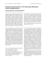
The sensitive tips of the thermocouples are located along the fuel centreline. Their axial
position is one at the half-height of the fuel meat and the other two 2.54 mm above and 2.54
mm below. Figure 6 shows the diagram of the instrumented fuel element and the Table I
presents its main characteristics (Gulf General Atomic, 1972). Figure 7 shows the
instrumented fuel element and one thermocouple inside a core channel.
Fig. 6. Diagram of the instrumented fuel element
Nuclear Reactors
8
Parameter Value
Heated length 38.1 cm
Outside diameter 3.76 cm
Active outside area 450.05 cm
2
Fuel outside area (U-ZrH
1.6
) 434.49 cm
2
Fuel element active volume 423.05 cm
3
Fuel volume (U-ZrH
1.6
) 394.30 cm
3
Power (total of the core = 265 kW) 4.518 kW
Table 1. Instrumented fuel element features
Fig. 7. IPR-R1 core top view with the instrumented fuel element in ring B and one probe
with thermocouple inside the core.
The instrumented fuel element was replaced to new positions and measures the fuel
temperature in each one of the core fuel rings (from B to F). At the same way, two
thermocouples were replaced to channels close to the instrumented fuel element to measure
the coolant channel temperature. Experiments were carried out with the power changing
from about 50 kW to 250 kW in 50 kW steps for each position of the instrumented fuel
element. The fuel and coolant temperatures were monitored as function of the thermal
power and position in the core.
In the TRIGA type reactors the buoyancy force induced by the density differential across the
core maintains the water circulation through the core. Countering this buoyancy force are
the pressure losses due to the contraction and expansion at the entrance and exit of the core
as well as the acceleration and friction pressure losses in the flow channels. Direct
measurement of the flow rate in a coolant channel is difficult because of the bulky size and
low accuracy of flow meters. The flow rate through the channel may be determined
indirectly from the heat balance across the channel using measurements of the water inlet
Experimental Investigation of Thermal Hydraulics in the IPR-R1 TRIGA Nuclear Reactor
9
and outlet temperatures. Two type K (chromel–alumel) thermocouples fixed in two rigid
aluminum probes (7.9 mm of diameter), were inserted into the core in two channels close to
position B1 (Channel 1 and 1’ in Fig. 4 and Fig. 5) and measured the inlet and outlet coolant
channel temperatures. The probes penetrated axially the channels through small holes in the
core upper grid plate. The probes were positioned in diametrically opposite channels, so
that when a probe measured the channel entrance temperature, the other one registered the
channel exit temperature. In a subsequent run, the probe positions were inverted. This
procedure was used also for the Channels 1’, 2’, 3’, 4’ and 5’ (Fig. 5). There is no hole in the
top grid plate in the direction of the Channel 0; so it was not possible to measure its
temperature. The inlet and outlet temperatures in Channel 0 were considered as being the
same of Channel 1. For the other channels there are holes in the top grid plate where it was
possible to insert the temperature probes. To found the bulk coolant temperature axial
profile at hot channel, with the reactor operating at 250 kW, the probe that measures the
channel inlet temperature was raised in steps of 10 cm and the temperature was monitored.
The same procedure was done with the reactor operating at 100 kW, but the probe was
raised in steps of 5 cm.
3.2 Hydraulic parameters of the coolant
The mass flow rate through the core coolant channels was determined indirectly from the
heat balance across each channel using measurements of the water entrance and exit
temperatures. Although the channels are laterally open, in this work cross flow or mass
transfer between adjacent channels was ignored. Inlet and outlet coolant temperatures in
channels were measured with two rigid aluminum probes with thermocouples. They were
inserted in the upper grid plate holes (Fig. 5). Figure 8 illustrates schematically the general
natural convection process established by the fuel elements bounding one flow channel in
the core. The core coolant channels extend from the bottom grid plate to the top grid plate.
The cooling water flows through the holes in the bottom grid plate, passes through the
lower unheated region of the element, flows upwards through the active region, passes
through the upper unheated region, and finally leaving the channel through the differential
area between a triangular spacer block on the top of the fuel element and a round hole in the
grid. As mentioned, in natural convection the driving force is supplied by the buoyancy of
the heated water in the core channels.
In a typical TRIGA flow channel entire fuel element is cooled by single phase convection as
long as the maximum wall temperature is kept below that required to initiate boiling.
However, at higher power levels the inlet and outlet regions of the core, where the heat
fluxes are the lowest, the channels are cooled by single phase convection. In the central
region, where the axial heat flux is highest, the mode of heat transfer is predominantly
subcooled boiling (Rao et al., 1988 and Mesquita et al. 2011).
The channel heating process is the result of the thermal fraction contributions of the
perimeter of each fuel around the channel. So there was an average power of 4.518 kW
dissipated in each stainless steel cladding fuel element and 4.176 kW dissipated in each
aluminum cladding fuel element at 265 kW core total power. The values are multiplied by
the fuel element axial power distribution and core radial power distribution factors as
shown in profiles of Fig. 9.
Nuclear Reactors
10
Fig. 8. A scheme of one flow channel in the TRIGA core
Fig. 9. Core radial and fuel element axial power profiles
The power axial distribution factor in the fuel is 1.25, according with Marcum (2008). Figure
10 shows in detail the coolant channels geometry. The core radial power distribution factors,
shown in Fig. 10, were calculated by Dalle et al. (2002) using WIMS-D4 and CITATION
Experimental Investigation of Thermal Hydraulics in the IPR-R1 TRIGA Nuclear Reactor
11
codes. The products are multiplied by the fractions of the perimeters of each fuel in contact
with the coolant in each channel. The two hottest channels in the core are Channel 0 and
Channel 1’. Channel 0 is located closer to the core centre, where density of neutron flux is
larger, but there is no hole in the top grid plate in the direction of this channel. Table 1 gives
the geometric data of the coolant channels and the percentage of contribution relative to
each fuel element to the channels power (Veloso, 2005 and Mesquita, 2005).
Fig. 10. Core coolant channels geometry and radial power distribution
Channel
Number
Area
[cm
2
]
Wetted
Perimeter
[cm]
Heated
Perimeter
[cm]
Hydraulic
Diameter
[cm]
Channel
Power
[%]
0 1.5740 5.9010 3.9060 1.0669 1.00
1’ 8.2139 17.6427 15.1556 1.8623 3.70
2’ 5.7786 11.7456 11.7456 1.9679 2.15
3’ 5.7354 11.7181 11.7181 1.9578 1.83
4’ 5.6938 11.7181 8.6005 1.9436 1.13
5’ 3.9693 10.8678 3.1248 1.4609 0.35
Table 2. Channel geometry and hydraulic parameters (Veloso, 2005; Mesquita, 2005)
Nuclear Reactors
12
The mass flow rate in the hydraulic channel ( m
) in [kg/s] is given indirectly from the
thermal balance along the channel using measurements of the water inlet and outlet
temperatures:
c
p
q
m
cT
(1)
Where q
c
is the power supplied to the channel [kW], c
p
is the isobaric specific heat of the
water [J/kgK] and ΔT is the temperature difference along the channel [
o
C]. The mass flux G
is given by: G = m
/ channel area. The velocity u is given by u = G / ρ, where ρ is the water
density (995 kg/m
3
). The values of the water thermodynamic properties were obtained as
function of the bulk water temperature at the channel for the pressure 1.5 bar (Wagner &
Kruse, 1988) Reynolds number (Re), used to characterize the flow regime, is given by:
Re
w
GD
(2)
Where G is the mass flux in [kg/m
2
s], D
w
is the hydraulic diameter in [m] and μ is the
dynamic viscosity [kg/ms].
3.3 Pool temperatures
Nine thermocouples and one platinum resistance thermometer (PT-100) were used to
monitoring the reactor pool temperature. The thermocouples were positioned in a vertical
aluminum probe and the first thermocouple was 143 mm above the core top grid plate. The
reactor operated during a period of about eight hours at a thermal power of 265 kW before
the steady state was obtained. The forced cooling system was turned on during the
operation. This experiment is important to understand the behavior of the water
temperature in the pool and evaluate the height of the chimney effect.
3.4 Temperatures with the forced cooling system turned off
The power of the IPR-R1 TRIGA was raised in steps of about 25 kW until to reach 265 kW.
The forced cooling system of the reactor pool was turned off during the tests. The increase of
the power was allowed only when all the desired quantities had been measured and the
given limits were not exceeded. After the reactor power level was reached, the reactor was
maintained at that power for about 15 min, so the entire steady-state conditions were not
reached in the core and coolant. The fuel temperature data was obtained by using the
instrumented fuel element. The fuel temperature measurements were taken at location B1 of
the core (hottest position). The outlet temperature in the channel was measured with
thermocouple inserted near the B1 position. One platinum resistance thermometer
measured the water temperature in the upper part of the reactor tank. Two thermocouples
measured the ambient temperatures around the reactor pool. The IPR-R1 reactor has a
rotary specimen rack outside the reactor core for sample irradiation. It is composed by forty
irradiation channels in a cylindrical geometry. One type K thermocouple was put during the
experiment in Position 40 of the rotary specimen rack (Fig. 5).
Experimental Investigation of Thermal Hydraulics in the IPR-R1 TRIGA Nuclear Reactor
13
3.5 Critical heat flux and DNBR
As the power in the IPR-R1 TRIGA core is increased, nucleation begins to occur on the fuel
rod surfaces. The typical pool boiling curve (Fig. 11) is represented on a log-log plot of heat
flux versus wall superheat (T
sur
– T
sat
). At low values of ΔT
sat
the curve is fairly linear, hence
the convective heat transfer coefficient (h) is relatively constant. There is no bubble
formation and the heat transfer occurs by liquid natural convection. At about ten to twenty
degrees above saturation the heat flux increases rapidly with the increasing of the wall
temperature. The increase in heat transfer is due to nucleate boiling. The formation of vapor
bubbles increases the turbulence near the heated surface and allows mixing of the coolant
fluid in the film region, thus enhancing the heat transfer rate (Haag, 1971). From the shape
of the curve, it can be seen that the heat transfer coefficient increases dramatically in the
boiling regime.
Fig. 11. Typical pool boiling curve for water under atmospheric pressure
Whenever the surface temperature of a solid exceeds the saturation temperature, local
boiling may occur even if the bulk water temperature is below the saturation temperature.
The water temperature in the boundary layer on the heated surface can become sufficiently
high so that subcooled pool boiling takes place. The bubbles will be condensed upon leaving
this boundary layer region because the bulk water is below the saturation temperature. By
increasing the surface temperature, the heat flux can reach the critical heat flux where the
film boiling occurs. At this point the bubbles become so numerous that they form an
insulating layer of steam around the fuel element and the heat flux is reduced significantly.