Check Point VSX NGX R67 for R75 Administration Guide pdf
Bạn đang xem bản rút gọn của tài liệu. Xem và tải ngay bản đầy đủ của tài liệu tại đây (5.05 MB, 205 trang )
15 December 2010
Administration Guide
Check Point VSX
NGX R67 for R75
© 2010 Check Point Software Technologies Ltd.
All rights reserved. This product and related documentation are protected by copyright and distributed under
licensing restricting their use, copying, distribution, and decompilation. No part of this product or related
documentation may be reproduced in any form or by any means without prior written authorization of Check
Point. While every precaution has been taken in the preparation of this book, Check Point assumes no
responsibility for errors or omissions. This publication and features described herein are subject to change
without notice.
RESTRICTED RIGHTS LEGEND:
Use, duplication, or disclosure by the government is subject to restrictions as set forth in subparagraph
(c)(1)(ii) of the Rights in Technical Data and Computer Software clause at DFARS 252.227-7013 and FAR
52.227-19.
TRADEMARKS:
Refer to the Copyright page ( for a list of our trademarks.
Refer to the Third Party copyright notices ( for a list of
relevant copyrights and third-party licenses.
Important Information
Latest Software
We recommend that you install the most recent software release to stay up-to-date with the latest functional
improvements, stability fixes, security enhancements and protection against new and evolving attacks.
Latest Documentation
The latest version of this document is at:
For additional technical information, visit the Check Point Support Center
().
Revision History
Date
Description
8 December 2010
First release of this document
Feedback
Check Point is engaged in a continuous effort to improve its documentation.
Please help us by sending your comments
(mailto:?subject=Feedback on Check Point VSX NGX R67
Administration Guide).
Contents
Important Information 3
Introduction to VSX 9
Product Names 9
VSX Glossary 9
VSX Overview 10
How VSX Works 10
Physical Network Topology 11
VSX Virtual Network Topology 11
Key Features and Benefits 12
Scalable Virtual Environment 12
High Performance Security 12
Non-Stop Security 12
Active/Standby Bridge Mode 12
Link Aggregation 12
SecurePlatform 12
URL Filtering 13
Hardware Health Monitoring 13
Typical VSX Deployments 13
VSX Gateway/Cluster Member Licenses 13
VSX Architecture and Concepts 14
Overview 14
The VSX Gateway 14
Management Server Connections 14
Management Interface 16
Virtual Devices 17
Virtual System 17
Virtual System in Bridge Mode 17
Virtual Routers 18
Virtual Switches 19
Interfaces 19
VSX Management Overview 21
Introduction 21
Security Management Model 22
Multi-Domain Security Management Model 22
Management Model Comparison 23
Management Server Communication - SIC 23
VSX Traffic Flow 24
Overview 24
Context Determination 24
Security Enforcement 26
Forwarding to Destination 26
VSX Routing Concepts 26
Routing Overview 26
Routing Between Virtual Systems 26
Source-Based Routing 28
NAT 29
Dynamic Routing 29
VSX Clusters 29
High Availability 30
Virtual System Load Sharing (VSLS) 30
Configuring VSX 31
Overview 31
Working with VSX Gateways 31
Creating a New VSX Gateway 31
Modifying VSX Gateway Definitions 36
Deleting a VSX Gateway 41
VSX Gateway Recovery 41
Working with Virtual Systems 41
Creating a New Virtual System 42
Modifying a Virtual System Definition 46
Deleting a Virtual System 50
Working with Virtual Switches 50
Adding Virtual Switches 50
Modifying Virtual Switches 51
Deleting a Virtual Switch 52
Working with Virtual Routers 52
Creating a New Virtual Router 54
Modifying a Virtual Router Definition 55
Deleting a Virtual Router 57
Working with Source-Based Routing 57
Working with Dynamic Routing 59
Working with Interface Definitions 59
Adding a New Interface 59
Modifying an Interface Definition 63
Deleting an Interface 63
Working with Authentication 63
Supported Authentication Schemes 63
Configuring RADIUS or TACACS/TACACS+ 64
Configuring SecurID ACE/Server 64
Client/Session Authentication 66
VSX Limitations 66
Configuring Client/Session Authentication 66
Working with Network Address Translation 68
Configuring NAT 68
Tracking Activity with SmartView Monitor 69
Using VSX with Multi-Domain Security Management 70
Overview 70
VSX Provisioning 71
Working with Virtual Devices 71
Adding Virtual System to a Domain Management Server 72
Adding Virtual Routers and Switches to a Domain Management Server 72
Introduction to VSX Clusters 73
VSX Clustering Overview 73
Physical Clusters 73
VSX Clusters 74
Supported Cluster Environments 74
Planning a Cluster Deployment 74
VSX Cluster Architecture 75
VSX High Availability 75
VSX Gateway High Availability 76
Per Virtual System High Availability 76
Virtual System Load Sharing (VSLS) 77
Requirements 77
Conceptual Overview 77
Failure Recovery 80
Bridge Mode 80
Spanning Tree Protocol (STP) Bridge Mode 80
Active/Standby Bridge Mode 81
Using Virtual Switches in a Cluster 83
Managing VSX Clusters 84
Configuration Overview 84
Creating a New Cluster 84
Defining Cluster General Properties 85
Selecting Creation Templates 85
Adding Members 86
Defining Cluster Interfaces 87
Configuring Cluster Members 88
Cluster Management 88
Completing the Wizard 89
Modifying a Cluster Definition 89
Modifying Cluster Properties 89
Working with Cluster Members 97
Adding a New Member 98
Deleting a Member 98
Upgrading Cluster Members 99
Changing the Cluster Type 101
Converting from VSLS to High Availability 101
Converting from High Availability to VSLS 102
Sample Command Output 102
Configuring VSX High Availability 103
Enabling VSX Gateway High Availability 103
Enabling Per Virtual System High Availability 104
Configuring Virtual System Load Sharing 104
Enabling VSLS 104
Creating a New VSLS Cluster 105
Using the vsx_util vsls Command 105
Distributing Virtual Systems Amongst Members 107
Viewing VSLS Status 108
Exporting and Importing VSLS Configurations 109
Configuring Virtual Systems in Bridge Mode 111
Overview 111
STP Bridge Mode 111
Active/Standby Bridge Mode 113
Advanced Clustering Configuration 114
Clusters on the Same Layer-2 Segment 114
Monitoring all VLANs with ClusterXL 115
Enabling Dynamic Routing Protocols 116
Working with URL Filtering 118
Introduction 118
Terminology 118
Configuring URL Filtering 119
Enabling URL Filtering 119
Defining the URL Filtering Policy 119
Updating the Content Inspection Database 120
Password Bypass 121
URL Filtering Acceleration 121
Working with Link Aggregation 122
Link Aggregation Overview 122
Link Aggregation Terminology 122
How Link Aggregation Works 123
High Availability Overview 123
Load Sharing Overview 124
Bond Failover 124
Failover Support for VLANs 125
Bond Interface & Interface Limitations 125
Configuring Link Aggregation for High Availability 126
Defining the Interface Bond 126
Defining Slave Interfaces as Disconnected 126
Verifying that the Bond is Functioning Properly 127
Creating the Cluster. 127
Upgrading an Existing Deployment 127
Link Aggregation - Load Sharing Mode 129
Creating a Bond in a New Deployment 130
Upgrading an Existing Deployment 132
Configuring Cisco Switches for Load Sharing 136
Changing the Bond Interface Mode 137
Enslaving Interfaces to a Bond 137
Detaching Interfaces from a Bond 138
Deleting a Bond 138
Removing a Bond Interface from Virtual devices 138
Removing a Bond Interface From a VSX Object 139
Removing a Bond Interface from a VSX Gateway or Cluster Member 139
Reconfiguring Interface Connections 139
Changing an Existing Interface to a Bond 139
Troubleshooting Bonded Interfaces 140
Troubleshooting Workflow 140
Optimizing VSX 142
VSX Resource Control 142
Overview 142
Resource Control System Components 142
Virtual System Priorities 143
Working with VSX Resource Control 143
QoS Enforcement 145
Overview 145
Architecture 146
QoS Features 147
QoS Management 147
QoS Configuration 148
Hardware Health Monitoring 152
Introduction to Hardware Health Monitoring 152
RAID Monitoring with SNMP 152
Example RAID Monitoring OIDs 154
Sensors Monitoring with SNMP on VSX-1 Appliances 154
Example Sensors Monitoring OIDs 155
Sensors Monitoring with SNMP on Power-1 and UTM-1 Appliances 155
Sensors Monitoring Via the Web Interface on Power-1, UTM-1 and Smart-1 157
Deploying VSX 158
Introduction 158
Internal Network Deployment Strategies 158
Security Gateway Deployment on a Physical Network 158
VSX Virtual System Deployment Strategies 159
Physical Internal Interface for Each Virtual System 159
Virtual Systems with Internal VLAN Interfaces 159
Internal Virtual Router with Source-Based Routing 160
Virtual Systems in the Bridge Mode 161
Cluster Deployments 161
Organizational Deployment Strategies 164
Enterprise Deployments 164
Managed Service Providers Using Multi-Domain Security Management 167
Data Centers 169
Migrating from an Open Server to a VSX-1 Appliance 170
VSX Diagnostics and Troubleshooting 172
Introduction 172
General Troubleshooting Steps 172
Troubleshooting Specific Problems 173
Cannot Establish SIC Trust for Gateway or Cluster 173
SIC Trust Problems with new Virtual Devices 174
Re-establishing SIC Trust with Virtual Devices 174
Sync Networks Do Not match 174
Install Policy Error Using VSX Creation Wizard 174
Internal Host Cannot Ping Virtual System 175
Command Line Reference 177
Firewall Commands 177
fw getifs 177
fw monitor 178
fw tab 178
fw fetch 179
VSX Command 180
vsx fetch 180
vsx fetchvs 181
vsx get 182
vsx set 182
vsx stat 182
vsx start_dr 183
vsx sic reset 184
Link Aggregation CLI Commands 184
cphaconf show_bond 184
chpaconf failover_bond 185
cphaprob -a if 185
VSX Resource Control Commands 185
vsx resctrl enforce 186
vsx resctrl monitor 186
vsx resctrl traffic_stat 186
vsx resctrl reset 186
vsx resctrl start 187
vsx resctrl stat 187
The vsx_util Command 188
add_member 189
add_member_reconf 190
change_interfaces 190
change_mgmt_ip 191
change_mgmt_private_net 191
fw fetch 192
change_interfaces 192
change_mgmt_subnet 194
convert_cluster 194
reconfigure 194
remove_member 195
show_interfaces 195
upgrade 196
view_vs_conf 196
vsls 198
The cphaprob Command 199
Index 201
Page 9
Chapter 1
Introduction to VSX
In This Chapter
Product Names 9
VSX Glossary 9
VSX Overview 10
How VSX Works 10
Key Features and Benefits 12
Typical VSX Deployments 13
VSX Gateway/Cluster Member Licenses 13
Product Names
Explanations and procedures included in this Administration Guide can apply to several brand names
representing editions or variations of Check Point products. This document uses generic product names for
variations of similar Check Point products.
The table below shows the generic product names used in this document and their product variations:
Generic Product
Name
Includes the Following Products
Security Gateway
VPN-1 Power
VPN-1 UTM
VPN-1 UTM Edge
VPN-1 UTM Embedded
VPN-1 Pro
VPN-1 Express
Any other Check Point products with VPN-1
functionality
Multi-Domain
Security
Management
Multi-Domain Security Management
SiteManager-1
SecurePlatform
SecurePlatform
SecurePlatform Pro
VSX Glossary
Term
Definition
VSX
Virtual System Extension - Check Point virtual networking solution,
hosted on a single computer or cluster containing virtual
abstractions of Check Point Security Gateways and other network
devices. These virtual devices provide the same functionality as
their physical counterparts.
VSX Overview
Introduction to VSX Page 10
Term
Definition
VSX Gateway
Physical server that hosts VSX virtual networks, including all
virtual devices that provide the functionality of physical network
devices.
Management Server
The Security Gateway or a Multi-Domain Security Management
Domain Management Server used by administrators to manage
the VSX virtual network and and its security policies.
Virtual Device
Generic term for any VSX virtual network component
Virtual System
Virtual device that provides the functionality of a physical Security
Gateway that provides full firewall VPN, and IPS functionality.
Virtual System in the
Bridge Mode.
A Virtual System that implements native layer-2 bridging instead of
IP routing, thereby enabling deployment of Virtual Systems in an
existing topology without reconfiguring the IP routing scheme
Virtual Switch
Virtual device that provides the functionality of a physical switch in
a VSX deployment
Virtual Router
Virtual device that provides the functionality of a physical router in
a VSX deployment
Virtual Interface
Virtual device that provides the functionality of a physical interface
on a virtual device
Warp (wrp) Link
A Virtual Interface that is created automatically in a VSX topology
VSX Overview
VSX (Virtual System Extension) is a security and VPN solution for large-scale environments based on the
proven security of Check Point Security Gateway. VSX provides comprehensive protection for multiple
networks or VLANs within complex infrastructures. It securely connects them to shared resources such as
the Internet and/or a DMZ, and allows them to safely interact with each other. VSX is supported by IPS™
Services, which provide up-to-date preemptive security.
VSX incorporates the same patented Stateful Inspection and Application Intelligence technologies used in
the Check Point Security Gateway product line. It runs on high speed platforms (known as VSX gateways)
to deliver superior performance in high-bandwidth environments. Administrators manage VSX using a
Security Gateway or a Multi-Domain Security Management Multi-Domain Server, delivering a unified
management architecture that supports enterprises and service providers.
A VSX gateway contains a complete set of virtual devices that function as physical network components,
such as Security Gateway, routers, switches, interfaces, and even network cables. Centrally managed, and
incorporating key network resources internally, VSX allows businesses to deploy comprehensive firewall
and VPN functionality, while reducing hardware investment and improving efficiency.
How VSX Works
Each "virtual" Security Gateway (known as a Virtual System in VSX terminology) functions as an
independent firewall, protecting a specific network. Once packets arrive at the VSX gateway, it directs traffic
to the Virtual System protecting the destination network. The Virtual System inspects all traffic and passes
or rejects it according to rules contained in its Rule Base.
In order to better understand how virtual networks work, it is important to compare physical network
environments with their virtual (VSX) counterparts. While physical networks consist of many hardware
components, VSX virtual networks reside on a single configurable VSX gateway or cluster that defines and
protects multiple independent networks, together with their virtual components.
How VSX Works
Introduction to VSX Page 11
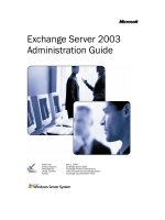
Physical Network Topology
The figure below shows a typical deployment with four physical Security Gateways, each protecting a
separate network. Each Security Gateway is a separate, physical machine that is hard-wired to the
perimeter router and its corresponding network.
Figure 1-1 Separate physical gateways protecting each network
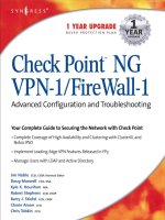
VSX Virtual Network Topology
The figure below illustrates how a single VSX gateway, in this case containing four Virtual Systems, protects
all four networks.
Figure 1-2 A VSX gateway replaces multiple physical gateways
Each Virtual System in the above figure functions as an individual Security Gateway, providing the same
security and networking functionality as a physical gateway. This diagram also shows:
Four Virtual Systems, each handling packet traffic to and from discrete networks.
One Virtual Switch providing connectivity for all the Virtual Systems to the Internet router.
Key Features and Benefits
Introduction to VSX Page 12
"Virtual" interfaces and network cables (known as Warp Links) providing point-to-point connections
between the Virtual Systems and the Virtual Switch.
Key Features and Benefits
Scalable Virtual Environment
Up to 250 virtual devices can be deployed on a single VSX gateway or VSX cluster, providing a highly
scalable virtual platform while reducing hardware investment, space requirements, and maintenance costs.
High Performance Security
High-bandwidth networks require high-performance gateways in order to support thousands of applications
and users. To provide security at wire speed, VSX can be deployed on multiple carrier-class platforms using
Check Point's SecureXL™ performance technology, ensuring secure, multi-gigabit throughput.
Virtual System Load Sharing (VSLS) provides the ability to distribute Virtual Systems across cluster
members, effectively distributing Virtual System traffic load within a cluster.
VSX Resource Control allows administrators to manage the processing load by guaranteeing that each
Virtual System will receive its minimum CPU allocation. Resources not needed by one Virtual System are
automatically made available to other Virtual Systems.
VSX QoS Enforcement provides the ability to control network quality of service in the VSX network
environment by supporting the Differentiated Services (DiffServe) protocol and assigning different
transmission characteristics to different classes of service.
Non-Stop Security
VSX supports the Check Point ClusterXL technology as well as third-party cluster solutions, such as
Crossbeam and Nokia, to guarantee nonstop security. Seamless connection failover promotes high
availability and resiliency, ensuring, nonstop, secure business operations at both the application and
network levels.
Active/Standby Bridge Mode
The Active/Standby Bridge Mode enhances network resiliency by enabling instantaneous failover and by
providing full support for VSLS in the Bridge Mode. This feature also provides full control over bridge
failover.
Link Aggregation
Link Aggregation, also known as Interface Bonding, lets you join interfaces for High Availability or Load
Sharing. This networking technology binds together multiple physical interfaces to increase reliability and
throughput.
In a High Availability deployment, only one interface is active at a time. If that interface or connection fails,
the bond manages the failover to a standby slave interface.
In a load sharing deployment, Link Aggregation significantly increases total throughput by spreading the
traffic load amongst multiple interfaces. All interfaces are active, and traffic is balanced between interfaces.
Load Sharing operates according to the IEEE 802.3ad or the XOR standard.
SecurePlatform
This release includes the latest enhancements to the SecurePlatform operating system.
SecurePlatform of this release is based on Linux kernel 2.6.18-92cp and Red Hat Enterprise Linux 5.2 for
user mode components and supports a large variety of hardware, including open servers, network cards and
Typical VSX Deployments
Introduction to VSX Page 13
RAID controllers. A comprehensive list of certified hardware can be found at:
(
URL Filtering
URL Filtering enforces filtering rules based on organizational needs and predefined categories made up of
URLs and URL patterns. URL Filtering takes place according to predefined categories made up of URLs
and/or IPs. The URL Filter checks the URL and/or IP of a Web page against a list of approved sites. In this
way, complete sites or pages within sites that contain objectionable material (pornography, pirated music or
videos, illegal software, etc.) can be blocked. In addition, the URL Filtering policy only checks connections
that have already passed the security policy.
Hardware Health Monitoring
SecurePlatform includes new Hardware Health Monitoring capabilities, support for RAID and Sensors
monitoring over SNMP.
Typical VSX Deployments
VSX virtual networking provides an ideal solution for a variety of deployment scenarios ("Deploying VSX" on
page 158):
Enterprises enforcing distinct security policies per department
Internet service providers offering secure environments
College campuses with many discrete networks for students, faculty and administration
Any other large organization requiring multiple firewalls
In each case, VSX provides access control, NAT, VPN, remote access, logging, and IPS services. For more
detailed information regarding VSX.
VSX Gateway/Cluster Member Licenses
Each VSX gateway or cluster member requires its own license, bound to the gateway or cluster member IP
address. Each gateway/cluster license covers a predefined number of Virtual Systems (10, 25, 50, 100 and
250) and these licenses are cumulative.
Page 14
Chapter 2
VSX Architecture and Concepts
In This Chapter
Overview 14
The VSX Gateway 14
Virtual Devices 17
VSX Management Overview 21
VSX Traffic Flow 24
VSX Routing Concepts 26
VSX Clusters 29
Overview
This chapter presents an overview of core VSX concepts and describes the architecture and building blocks
that comprise a VSX virtual environment. This information is essential in order to plan, provision, configure,
and operate a VSX virtual network deployment. VSX includes a robust set of virtual components that
emulate the functionality of physical network devices. By using these virtual components, you can create
network topologies that are functionally equivalent to physical networks.
The term "Virtual Devices" refers to Virtual Systems, Virtual Switches, and Virtual Routers.
This chapter also introduces the two principal management models with which you manage the VSX
environment. Finally, this chapter describes several routing and traffic management features that are
applicable to VSX environments.
The VSX Gateway
A VSX gateway is a physical machine that hosts virtual "networks", consisting of virtual devices that
provide the functionality of their physical network counterparts such as: Security Gateways, routers and
switches.
A VSX gateway performs the following tasks:
Communicates with the management server to handle provisioning and configuration for all virtual
devices
Manages state synchronization to for high availability and for load sharing in cluster deployments.
Management Server Connections
A management server (Security Gateway or Multi-Domain Security Management Multi-Domain Server)
connects to the VSX gateway and provides provisioning and configuration services for virtual devices
located on the VSX gateway. You can connect the management server to the VSX gateway using one of the
following scenarios.
Local Connection: The management server connects directly to the VSX gateway via a dedicated
management interface.
Remote Connection: The management server connects remotely from an external or internal network
by means of a router connected to a management interface. This method ensures segregation of
management traffic from all other traffic.
The VSX Gateway
VSX Architecture and Concepts Page 15
Local Management Connection
When using a local management server (Security Management Server or Multi-Domain Security
Management), all management traffic is handled by a dedicated management interface (DMI) that connects
the management server with the VSX gateway. The dedicated management interface IP address can be
either private or public.
Figure 2-3 Typical VSX topology using local management
Remote Management connection
When using a remote management server (Security Gateway or Multi-Domain Security Management),
management traffic travels via an internal or external network to a VSX gateway to the management
interface. This architecture segregates management traffic from all other traffic passing through the VSX
gateway.
The VSX Gateway
VSX Architecture and Concepts Page 16
Check Point recommends that remote management connections use a dedicated management interface
(DMI) that connects directly to a router or switch that leads to the external network or the Internet. The
following diagram illustrates this scenario.
Figure 2-4 Typical VSX deployment with DMI remote management
You can choose to use a non-dedicated management interface by connecting a Virtual Router or Virtual
Switch to the management interface. This, however, is not recommended.
When management traffic passes through a Virtual Router or Switch, you must ensure that the associated
Warp Link IP address originates from the remote network. Furthermore, if the remote management
connection arrives via the Internet, you must assign a routable, public IP address.
Management Interface
A VSX deployment can be managed using one of the following interface schemes:
Dedicated Management Interface (DMI): Uses a separate interface that is restricted to management
traffic, such as provisioning, logging and monitoring
Non-Dedicated Management Interface: Uses a shared internal or external interface that also carries
routine user traffic
Dedicated Management Interface (DMI)
Check Point recommends that you use a DMI for management for the following reasons:
Segregation of management traffic from routine "production" traffic enhance performance, especially for
end users
Enables several advanced VSX features
Non-Dedicated Management Interface
VSX supports non-DMI deployments primarily to provide backward compatibility with legacy deployments.
When configuring a non-DMI deployment, you can define remote management connections only via a
Virtual Switch or Virtual Router. Remote management connects via a Virtual System are not supported.
Check Point does not recommend using non-DMI for the following reasons:
Virtual Devices
VSX Architecture and Concepts Page 17
Provisioning and logging may degrade user performance
Does not support several new VSX features
Non-DMI is irreversible - you cannot change a non-DMI gateway to DMI
Virtual Devices
This section describes virtual network components and their characteristics.
Virtual System
A Virtual System is a virtual security and routing domain that provides the functionality of a Security
Gateway with full firewall and VPN facilities. Multiple Virtual Systems can run concurrently on a single VSX
gateway.
Virtual System Autonomy
Each virtual system functions as a stand-alone, independent entity, much in the same way as each Security
Gateway is independent from other gateways. Each Virtual System maintains its own interfaces, IP
addresses, routing table, ARP table and dynamic routing configuration. In addition, each Virtual System
maintains its own:
State Tables: Each Virtual System contains its own kernel tables containing configuration and runtime
data, such as, active connections, IPSec tunnel information, etc.
Security and VPN policies: Each Virtual System enforces its own security and VPN Policies (including
INSPECT code). Policies are retrieved from the management server and stored separately on the local
disk and in the kernel. In a Multi-Domain Security Management environment, each Domain database is
maintained separately on the management server as well as on the VSX gateway.
Configuration Parameters: Each Virtual System maintains its own configuration, such as IPS settings,
TCP/UDP time-outs, etc.
Logging Configuration: Each Virtual System maintains its own logs and performs logging according to
its own rules and configuration.
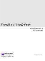
Virtual System in Bridge Mode
A Virtual System in the bridge mode implements native layer-2 bridging instead of IP routing. This allows
network administrators to easily and transparently deploy a Virtual System in an existing network topology
without reconfiguring the existing IP routing scheme.
Virtual Devices
VSX Architecture and Concepts Page 18
A typical bridge mode scenario incorporates an 802.1q compatible VLAN switch on either side of the VSX
gateway. The Virtual System interfaces do not require IP addresses and it remains transparent to the
existing IP network.
Figure 2-5 Virtual System in the Bridge Mode
A Virtual System in the bridge mode:
Has the same security capabilities as a Virtual System, except for VPN and NAT
Simplifies virtual network management
Does not segment an existing virtual network
Requires manual topology configuration in order to enforce anti-spoofing
Virtual Routers
A Virtual Router is an independent routing domain within a VSX gateway that performs the functionality of
physical routers. Virtual Routers are useful for connecting multiple Virtual Systems to a shared interface,
such as the interface leading to the Internet, and for routing traffic from one Virtual System to another.
Virtual Routers support dynamic routing.
Virtual Routers perform the following routing functions:
Packets arriving at the VSX gateway through a shared interface to the designated Virtual System based
on the source or destination IP address.
Traffic arriving from Virtual Systems directed to a shared interface or to other Virtual Systems.
Traffic to and from shared network resources such as a DMZ.
As with physical routers, each Virtual Router maintains a routing table with a list of route entries describing
known networks and directions on how to reach them. Depending on the deployment requirements multiple
Virtual Routers can be configured.
To protect themselves, Virtual Routers inspect all traffic destined to, or emanating from themselves (for
example, an ICMP ping to the Virtual Router IP address) based on the security policy. Traffic that is not
destined to, or emanating from the Virtual Router is not inspected by the Virtual Router policy and is
forwarded to its destination.
Virtual Devices
VSX Architecture and Concepts Page 19
Virtual Switches
By providing layer-2 connectivity, a Virtual Switch connects Virtual Systems and facilitates sharing a
common physical interface without segmenting the existing IP network. As with a physical switch, each
Virtual Switch maintains a forwarding table with a list of MAC addresses and their associated ports.
In contrast to a Virtual Router, when sharing a physical interface via a Virtual Switch there is no need:
To allocate an additional subnet for IP addresses of Virtual Systems connected to the switch.
To manually configure the routing on the routers adjacent to the shared interface.
You can create multiple Virtual Switches in a virtual network topology.
Note - When sharing a physical interface via a Virtual Switch, the IP
addresses for Virtual Systems connected to a Virtual Switch should be
allocated from the same subnet as the shared interface.
If the only function the Virtual Switch performs is to connect Virtual
Systems, then the Virtual Switch can be defined without interfaces
(unless Virtual System load sharing is enabled).
Interfaces
This section describes the various types of interfaces and how they are used in a VSX configuration. The
principal interface types are:
Physical Interface
VLAN interface
Warp Link (including unnumbered interfaces)
The following figure presents a simple example that illustrates how the various interface types are used in a
VSX environment.
Figure 2-6 VSX interface types
In the above figure:
Warp Links connect the Virtual Switch to each Virtual System.
Virtual Devices
VSX Architecture and Concepts Page 20
A Physical Interface connects the Virtual Switch to an external router leading to the Internet.
VLAN Interfaces connect the Virtual Systems to the VLAN Switch, via A VLAN trunk.
The VLAN switch connects to the protected networks.
Physical Interfaces
Physical interfaces connect a VSX gateway to internal and external networks, as well as to the management
server. There are three types of physical interfaces (four types for a VSX Cluster) used in a VSX gateway:
Dedicated Management Interface: Connects the VSX gateway to the management server when it is
locally managed. If the VSX gateway is remotely managed, then the management connection arrives via
the external or internal interface.
External interface: Connects the VSX gateway to the Internet or other untrusted networks.
Internal Interface: Connects the VSX gateway to a protected network.
Synchronization Interface: Connects one VSX gateway member to other members for state
synchronization in a VSX clustering deployment.
Additional physical interfaces can be installed and attached to any virtual device as required. A VSX
gateway can theoretically contain as many physical interfaces as permitted by gateway hardware and
memory constraints.
VLAN Interfaces
Virtual Systems typically connect to protected VLAN networks using IEEE 802.1q compliant VLAN
Interfaces. The networks are connected to ports on an 802.1q-compliant switch that trunks all traffic via a
single physical interface to the VSX gateway.
VSX uses VLAN tags to direct the Ethernet frames to the specific Virtual System handling each network.
VSX assigns a virtual VLAN interface to each VLAN tag on a specific physical interface. For Example: VLAN
tag 100 on eth3 will be assigned a virtual interface named eth3.100.
Warp Links
A Warp Link is a virtual point-to-point connection between a Virtual System and a Virtual Router or Virtual
Switch. Each side of a Warp Link represents is a virtual interface with the appropriate virtual device.
VSX automatically assigns a name to each virtual interface when the administrators creates the link. Warp
Interfaces on the Virtual System side are assigned the prefix wrp and those on the Virtual Router/Switch
side are assigned the prefix wrpj. In both cases, VSX appends a unique number to the prefix to form the
interface name.
When connected to a Virtual Switch, VSX also assigns a unique MAC address to each Warp Link.
VSX Management Overview
VSX Architecture and Concepts Page 21
Unnumbered Interfaces
VSX allows you reduce the number of IP addresses required for a VSX network deployment when using one
or more Virtual Routers. A Warp link connected to a Virtual Router can "borrow" an existing IP address from
another interface, instead of assigning a dedicated address to the interface leading to a Virtual Router. This
capability is known as an Unnumbered Interface.
Figure 2-7 Unnumbered interfaces
The above figure illustrates a topology using unnumbered interfaces. In this example, the external interfaces
for each Virtual System are unnumbered and borrow the IP address of the internal interfaces. Unnumbered
interfaces act as the next hop from the Virtual Router.
Unnumbered Interface Limitations
The following limitations apply to Unnumbered Interfaces:
Unnumbered interfaces must connect to a Virtual Router.
You can only "borrow" an individual interface IP address once.
In order to use VPN or Hide NAT, the borrowed address must be routable.
VSX Management Overview
Introduction
VSX supports two Check Point management models: Security Management and Multi-Domain Security
Management. Both models provide central configuration, management and monitoring for multiple VSX
gateways and Virtual Systems. The choice of management model depends on several factors, including:
The scale of the current deployment and anticipated expansion
Administrative requirements
Physical and operational requirements
Licensing restrictions
You can use either management model to manage "physical" Security Gateway together with VSX
gateways and Virtual Systems. You can also manage VPN communities and remote connections with either
model.
VSX Management Overview
VSX Architecture and Concepts Page 22
Note - According to the Check Point EULA (End User License
Agreement), a Security Gateway can only manage security policies for
Virtual Systems belonging to a single legal entity. In order to manage
Virtual Systems belonging to multiple legal entities, you need to deploy
a Multi-Domain Security Management management solution with a
separate Domain Management Server for each legal entity. For more
information regarding Licensing, refer to your Check Point Reseller.
Security Management Model
The Security Management model is appropriate for enterprise deployments containing up to 25 Virtual
Systems. In this model, SmartDashboard connects to the Security Gateway, which in turn manages the VSX
gateway.'
The Security Gateway provides a single management domain with one object database to manage Virtual
Devices as well as other physical devices. Only one administrator at a time can use SmartDashboard to
provision Virtual Systems, and configure security policies.
Multi-Domain Security Management Model
Using the Multi-Domain Security Management model, administrators centrally manage multiple independent
networks, typically belonging to different Domains, divisions or branches. The Multi-Domain Server is the
central management node that controls the network and security policy databases for each of these
networks.
Each Domain network is managed by a Domain Management Server, which provides the full functionality
of a Security Gateway and can host multiple Virtual Systems, virtual devices and physical devices. The
server that manages the VSX gateway is the Main Domain Management Server.
Check Point recommends that each VSX gateway in a Multi-Domain Security Management deployment be
managed by its own, separate, Main Domain Management Server. A VSX gateway can host Virtual Systems
that are managed by different Domain Management Servers.
Figure 2-8 Multi-Domain Security Management Managing VSX
Description
VSX Management Overview
VSX Architecture and Concepts Page 23
Description
1
SmartDomain Manager
2
Multi-Domain Server
3
SmartDashboard
4
Domain Management Server
5
Main Domain Management Server
6
VSX Gateway
7
VSX Virtual System in Domain Management Servers
Using the SmartDomain Manager, you provision and configure Domains and Domain Management
Servers. Each Domain Management Server uses its own SmartDashboard instance to provision and
configure its Virtual Systems, virtual devices, and security policies.
Management Model Comparison
The following table summarizes the capabilities and differences between the two management models. The
capacity figures shown for Multi-Domain Security Management represent estimated, practical limits that will
sustain acceptable performance levels under normal conditions. Actual capacities and performance are a
dependent on many factors, including deployed hardware, network topology, traffic load and security
requirements.
Table 2-1 VSX Management Model Comparison
Feature
Security
Management Server
Multi-Domain Security
Management (Practical Limit)
Management Domains
1
250
Concurrent Administrators
1
250
Object Databases
1
250
Policies
250
250
Certificate Authorities
1
250
Virtual Systems
25 (recommended)
250
Management Server Communication - SIC
All communication between the management server and the VSX gateway is accomplished by means of
Secure Internal Communication (SIC), a certificate based channel that authenticates communication
between Check Point components. The management server uses SIC for provisioning virtual devices, policy
installation, logging, and status monitoring.
SIC trust is initially established using a one-time password during configuration of the VSX gateway or
cluster members. For Multi-Domain Security Management deployments, SIC trust is established between
the Domain Management Server associated with the VSX gateway or cluster (Main Domain Management
Server).
Virtual devices establish trust in a different manner than their physical counterparts. When creating a virtual
device, VSX automatically establishes SIC trust using the secure communication channel defined between
the management server and the VSX gateway. The VSX gateway uses its management interface for Secure
Internal Communication between the management server and all virtual devices.
VSX Traffic Flow
VSX Architecture and Concepts Page 24
VSX Traffic Flow
Overview
The VSX gateway processes traffic according to the following steps:
Context determination
Security enforcement
Forwarding to destination
Context Determination
VSX incorporates VRF (Virtual Routing and Forwarding) technology that allows creation of multiple,
independent routing domains on a single VSX gateway or cluster. The independence of these routing
domains makes possible the use of virtual devices with overlapping IP addresses. Each routing domain is
known as a context.
When traffic arrives at a VSX gateway, a process known as Context Determination directs traffic to the
appropriate Virtual System, Virtual Router or Virtual Switch. The context determination process depends on
the virtual network topology and the connectivity of the virtual devices.
The three basic Virtual System connection scenarios are:
Virtual System directly connected to a physical or VLAN interface
Virtual System connected via a Virtual Switch
Virtual System connected via a Virtual Router
Direct Connection to a Physical Interface
When traffic arrives at an interface (either physical or VLAN) that directly connects to a Virtual System, the
connection itself determines the context and traffic passes directly to the appropriate Virtual System via that
interface. In the following example, VSX automatically directs traffic arriving via VLAN Interface eth1.200
to Virtual System 2 according to the context defined by the VLAN ID.
Figure 2-9 Directly connected interface example
VSX Traffic Flow
VSX Architecture and Concepts Page 25
Connection via a Virtual Switch
Traffic arriving via a Virtual Switch passes to the appropriate Virtual System based on the destination MAC
address, as defined in the Virtual Switch forwarding table. Traffic arrives at the Virtual System via the Warp
Link associated with the designated MAC address.
Figure 2-10 Typical Virtual Switch scenario
If the destination MAC address does not exist in the Virtual Switch forwarding table, the traffic is broadcast
over all defined Warp Links. The Virtual Switch scenario is common for inbound traffic from external
networks or the Internet.