integrate ann ga into improve particle classification algorithm in automotive production moving forward to green manufacturing
Bạn đang xem bản rút gọn của tài liệu. Xem và tải ngay bản đầy đủ của tài liệu tại đây (6.86 MB, 63 trang )
<span class="text_page_counter">Trang 1</span><div class="page_container" data-page="1">
MINISTRY OF EDUCATION AND TRAINING
<b>HO CHI MINH CITY UNIVERSITY OF TECHNOLOGY AND EDUCATION FACULTY FOR HIGH QUALITY TRAINING </b>
<b> </b>
<b>Ho Chi Minh City, March 2024GRADUATION PROJECT </b>
<b>MECHANICAL ENGINEERING TECHNOLOGY</b>
<b>INTEGRATE ANN-GA INTO IMPROVE PARTICLE CLASSIFICATION ALGORITHM IN AUTOMOTIVE PRODUCTION MOVING FORWARD TO GREEN </b>
<b>MANUFACTURING </b>
<b>LECTURER: PHAM HUY TUANSTUDENT: TRAN MINH THUAN</b>
<small>S K L 0 1 2 6 3 9</small>
</div><span class="text_page_counter">Trang 2</span><div class="page_container" data-page="2"><b>MINISTRY OF EDUCATION AND TRAINING </b>
<b>HO CHI MINH CITY UNIVERSITY OF TECHNOLOGY AND EDUCATION </b>
<b>FACULTY OF MECHANICAL ENGINEERING </b>
<b>GRADUATION PROJECT </b>
<i><b> Project title: </b></i>
<b>Advisor: PHAM HUY TUAN, Assoc. Prof. Dr. </b>
Student name: <b>TRAN MINH THUAN </b>
<b>Student ID: 19144205 </b>
<b>Academic year: 2019 - 2023 </b>
<b>Ho Chi Minh City, March 2024 </b>
<b>“ INTEGRATE ANN-GA INTO IMPROVE PARTICLE CLASSIFICATION ALGORITHM IN AUTOMOTIVE PRODUCTION MOVING FORWARD TO GREEN MANUFACTURING ” </b>
</div><span class="text_page_counter">Trang 3</span><div class="page_container" data-page="3"><small>HCMC UNIVERSITY OF TECHNOLOGY AND EDUCATION</small>
<b><small>FACULTY OF MECHANICAL ENGINEERING</small></b>
<small>THE SOCIALIST REPUBLIC OF VIETNAM </small>
<b><small>Independence – Freedom– Happiness </small></b>
---
<b>GRADUATION PROJECT ASSIGNMENT </b>
<b>Semester I/ 2023-2024 </b>Advisor: PHAM HUY TUAN, Assoc. Prof. Dr.
Student name: Tran Minh Thuan Student ID: 19144205
<i><b>1. Project code: CTM-112 </b></i>
<i><b>- Project Title: </b></i>
“Integrate ANN-GA into improve Particle Classification Algorithm in Automotive Production moving forward to Green Manufacturing”
<i><b>2. Initial Materials Provided by The Advisor: </b></i>
Input images and database are based on the doctoral thesis of Dr. Phan Quoc Bao: “Characterization of particles for Improving Cleanability in Automotive Production”.
<i><b>3. Content of the project: </b></i>
- Developing the ANN-GA algorithm on the database of the PhD thesis: “Characterization of particles for Improving Cleanability in Automotive Production”. - Evaluate the effectiveness of the new algorithm compared to the old classification method.
<i><b>4. Final product: </b></i>
- Improved the reliability of the classification algorithm on the platform developed with Taguchi from the input of high-tech manufacturing experts in the laboratory of the Korean car manufacturer Hyundai.
- Develop identification software for hardware of metal scrap sorting equipment, applied at the micro size particle, collected from 120 micromet grid filtering to support 20 micromet grid filtering classification
- Setting up the basic ANN classification algorithms to move forward into Particle Expert System and Web based Particle Classification System.
- Connect ANN and Robotic Automation Classification to form Hardware Set-up
<i><b>5. Date of assignment: 01/10/2023 6. Date of submission: 23/03/2024 7. Presentation language: </b></i>
<b> </b>
<i><small>(Sign with full name) (Sign with full name) (Sign with full name) </small></i>
<small> Protection is allowed ……… </small>
<i><small> (Advisor sign with full name) </small></i>
<i>Presentation protection: English Vietnamese </i>
</div><span class="text_page_counter">Trang 4</span><div class="page_container" data-page="4"><b>DISCLAIMER </b>
<b>Project title: INTEGRATE ANN-GA TO IMPROVE PARTICLE CLASSIFICATION ALGORITHM IN AUTOMOTIVE PRODUCTION MOVING FORWARD TO GREEN MANUFACTURING. </b>
<b>- Advisor: PHAM HUY TUAN, Assoc. Prof. Dr. - Student: TRAN MINH THUAN </b>
<b>- Student ID: 19144205 </b>
- Class: 19144CL1A - Phone: 0911521739
- Email:
- Disclaimer “In this graduate project, I present many examples and proposed modifications derived from texts found in published articles, used to illustrate certain principles. It's important to note that these examples are chosen to demonstrate specific and seemingly confusing points. Therefore, my edits are intended to clarify some information, while acknowledging that without direct communication with the author of the article, interpretations may differ. Furthermore, I would like to confirm that this graduation project is the product of my personal research and efforts. . I do not copy from any published articles without citing the original source. If there is any violation, I take full responsibility.”
Ho Chi Minh City, Ferbruary 19, 2024 Tran Minh Thuan
</div><span class="text_page_counter">Trang 5</span><div class="page_container" data-page="5"><b>ACKNOWLEDGEMENTS </b>
First of all, I would like to express my deep gratitude to my supervisor, Associate Professor Dr. Pham Huy Tuan, who has the professionalism of a doctoral associate professor and the dedication of a teacher. helped me complete the project successfully despite many obstacles, his expertise and insightful advice helped me shape my approach to writing this thesis. Without his persistent help, urging and reminders him, the goal of this project will not be realized.
I would like to express my deepest and most sincere thanks to Dr. Phan Quoc Bao, who allowed me to use my doctoral thesis as the foundation database for my project. Dr. Bao not only allowed me to use his research as a basis for integrating Artificial Neural Network and Genetic Algorithm (ANN-GA), but also gave me a great opportunity to gain practical experience and learned valuable lessons while working at his company. His mentorship, leadership and interest and help in my development were a source of inspiration and motivation. Dr. Bao's generosity in sharing his expertise as well as his role as both a teacher and a respected leader have been instrumental in this research and in the my future career.
I would like to express my sincere thanks to the teachers of the Faculty of Mechanical Engineering, Ho Chi Minh City University of Technical and Education for their support and assistance. The environment they have built is very conducive to learning and research, providing me with much-needed knowledge and experience to pursue my academic goals.
In addition, I would like to thank the management team at Vietnam Metal Hardware Co., Ltd, training me a lot of practical experience in the field of mechanical engineering. Practicial guidance in metal fabrication at site and support throughout my challenging time was invaluable. I would also like to thank my colleagues, M.A Pham Thanh Cong and Mr. Nguyen Ngoc Hoang Phi , who were indispensable in my research journey. Their collaboration, insight, and enthusiasm for our common research area have been instrumental in driving our research. Working alongside such dedicated and talented associates is both inspiring and rewarding.
Finally, I am indebted to my family for their love, encouragement, and endless sacrifices both physically and mentally. Without their support, this achievement would not have been possible.
Ho Chi Minh City, Ferbruary 19, 2024 Tran Minh Thuan
</div><span class="text_page_counter">Trang 6</span><div class="page_container" data-page="6"><b>ABSTRACT </b>
In pursuit of promoting Green Manufacturing in the automotive industry, this research integrates Artificial Neural Network (ANN) Genetic Algorithm (GA), called ANN-GA, to enhance the optimization of Particle Classification Algorithm (PCA) was previously developed by Taguchi method, then upgraded by Programming C++ and Matlab optimization function. This innovation comes from the need to solve the problem of automotive machinery small chip lodged and complex particles created in various engine processing processes such as casting, anodizing, machining, High-pressure water jet, anodizing, sandblasting, grinding, polishing, and assembly. These processes will induce the rist of creation of burr, cast and chip,... These particles lodge inside the transmission, engine and crankshaft, and then damage the functions of these components, posing risks to drivers, such as: suddenly increase speed until losing control, mal-function, suddenly stop engine, negative impact to valve control systems called TC21, TC35, TC 29… which mainly working based on the electro-magnetic oil sensors.
Based on the partical experiment in research of Dr. Phan Quoc Bao, and Professor Sung Lim Ko from the high-tech manufacturing laboratory at Hyundai Motor Korea, South Korea, and the Precison Machining Lab, Konkuk University, South Korea, from 2009 - 2015, has developed a particle expert system (PES) that proved the possibility to classify burrs, blanks and chips, by using very basic image processing techniques. An advanced model of PCA, consisting of 12 distinct particle types, was found by using ANN-GA. This new approach does not only trains PCA parameters with higher accuracy but also ensures a stable success rate, thereby improving the reliability of particle source identification processing. Even though the whole project result was statiscal evaluation, it showed up the trend of creating particle from different sources, processes of metal fabrication. These decisions may support the top leader CEO, Managers to make suitable decision to invest into suitable production technology related to improving Cleanability
This integration of ANN-GA into PCA is a forward-thinking approach to solving cleanability challenges in automotive manufacturing. It aligns with the principles of Green Manufacturing by providing a methodologically sound, environmentally friendly solution to improve product quality and safety. Here is the discussion from Professor Dornfield at ISGMA 2013 Sheraton Hawaii Waikiki Green Manufacturing International
<b>Conference. </b>
Ho Chi Minh City, Ferbruary 19, 2024 Tran Minh Thuan
</div><span class="text_page_counter">Trang 7</span><div class="page_container" data-page="7"><b>TABLE OF CONTENTS </b>
CHAPTER 1: OVERVIEW... 2
1.1. Overview of the research ... 2
1.2. The need for research ... 3
1.3. The goal of the research ... 4
1.4. The object and scope of research ... 4
1.4.1. The object of the research ... 4
1.4.1. The scope of the research ... 4
1.5. Approach and research method ... 4
1.5.1. Approach ... 4
1.5.2. Research methods ... 4
1.6. Project results ... 4
1.7. Efficiency specification ... 4
CHAPTER 2: BASIC THEORIES ... 5
2.1. Cleanability problems and technology. ... 5
2.1.1. Introduction ... 5
2.1.2. Advanced cleaning methods ... 6
2.1.3. Deburring Processes and Cleanability ... 7
CHAPTER 3: CHARACTERIZATION AND RECOGNITION OF PARTICLES FOR IMPROVING CLEANABILITY IN AUTOMOTIVE PRODUCTION ... 9
3.1. Mechanism of particles generation... 9
3.2. Standard for particle classification ... 13
3.3. Algorithm of classification ... 15
CHAPTER 4: INTEGRATING ANN-GA INTO THE CLASSIFICATION ALGORITHM ... 18
4.1. Introduce ANN-GA ... 18
4.1.1. Artificial Neural Network (ANN) ... 18
4.1.2. Genetic Algorithm (GA) ... 20
4.2. ANN training ... 22
4.2.1. Graphical representation of ANN model ... 22
4.2.2. Result and Discussion ... 24
4.3. Use GA from ANN data to optimize parameters ... 27
4.3.1. Function sim(x) to use ANN network for optimization ... 27
4.3.2. Optimization results using ANN-GA... 29
4.3.3. New PCA base on ANN-GA ... 32
CHAPTER 5: TESTING AND EVALUATION ... 33
5.1. Particle Classification System ... 33
5.1.1. Analysis process... 33
</div><span class="text_page_counter">Trang 8</span><div class="page_container" data-page="8">5.1.2. Image processing ... 33
5.1.3. Feature extraction... 35
5.1.4. Decision conditions ... 36
5.1.5. Particle Classification System... 37
5.1.6. Result particle classification system ... 38
5.2. Evaluate the results of the new algorithm based on ANN-GA ... 39
CHAPTER 6: NEW METHOD FOR PARTICLE CLASSIFICATION - BOUNDARY MATRIX ... 43
</div><span class="text_page_counter">Trang 9</span><div class="page_container" data-page="9"><b>LIST OF FIGURES </b>
<i><b>Fig. 1.1 Shows particles extracted from transmission by grid filter ... 2</b></i>
<i><b>Fig. 1.2 Intersection between casting surface and drilling holes of Automotive </b></i>
<i>Transmission at control valve ... 2</i>
<i><b>Fig. 1.3 </b>SEM analysis of particles with chemical composition and surface structure. ... 3</i>
<i><b>Fig. 2.1 Cleanability in the design-to manufacturing cycle and main influences[1] ... 5</b></i>
<i><b>Fig. 2.2 Design of intersection holes considering cleanability[3]... 5</b></i>
<i><b>Fig. 2.3 Chip morphology, formed by drilling & milling ... 6</b></i>
<i><b>Fig. 2.4 Real industrial cleanability problem in automotive ... 7</b></i>
<i><b>Fig. 2.5 Morphology of surface after different deburring processes ... 7</b></i>
<i><b>Fig. 2.6 Burrs at different locations after HPWJ & Brushing ... 8</b></i>
<i><b>Fig. 2.7 Burr at window after HPWJ and brushing ... 8</b></i>
<i><b>Fig. 3.1 </b>Samples with 4 areas: casting surface, machined surfaces (drilling and milling) ... 9</i>
<i><b>Fig. 3.2 </b>Stable burrs formed along the edge of a workpiece even after deburring process ... 10</i>
<i><b>Fig. 3.3. Unstable burr after machining or deburring process ... 10</b></i>
<i><b>Fig. 3.4. Generation of cast debris and cast surface ... 12</b></i>
<i><b>Fig. 3.5. Variety of chip shape ... 13</b></i>
<i><b>Fig. 3.6. Standard of particle classification after image processing to get clear </b>shape/boundary of particles ... 14</i>
<i><b>Fig. 3.7. Definition of shape parameters in (a) burr, (b) cast, (c) chip and (d) filament of </b>brush ... 14</i>
<i><b>Fig 3.8. Schematic illustration of Particle Classification Algorithm (PCA)[4] ... 17</b></i>
<i><b>Fig. 4.1. Basic working mechanism of neural networks ... 19</b></i>
<i><b>Fig. 4.2. MATLAB's Neural Network Toolbox ... 19</b></i>
<i><b>Fig. 4.3. Simple diagram explaining the GA algorithm ... 20</b></i>
<i><b>Fig. 4.4. Global Optimization Toolbox with GA in Matlab ... 21</b></i>
<i><b>Fig. 4.5. Graphical representation of ANN model ... 22</b></i>
<i><b>Fig. 4.6. Network achitecture ANN ... 22</b></i>
<i><b>Fig. 4.7. Use the Levenberg-Marquardt algorithm to train the ANN ... 23</b></i>
<i><b>Fig. 4.8. Validation and test data ... 23</b></i>
<i><b>Fig. 4.9. ANN training results for group 1 and group 2 ... 24</b></i>
<i><b>Fig. 4.10. Comparison of experimental SR% with ANN(Group 1) and ANN(Group 2) and </b>Taguchi predicted SR%. ... 25</i>
<i><b>Fig. 4.11. Contour Plot of SR% vs L2 and L3. ... 26</b></i>
<i><b>Fig. 4.12. Contour Plot of SR% vs R1 and L3. ... 26</b></i>
<i><b>Fig. 4.13. Contour Plot of SR% vs L2 and R1 ... 26</b></i>
<i><b>Fig. 4.14. How to transform when you need to find the maximum value using the </b>minimum value optimization algorithm ... 28</i>
<i><b>Fig. 4.15. New PCA base on ANN-GA ... 32</b></i>
<i><b>Fig. 5.1. Flow diagram of Particle Classification System (PCS) ... 33</b></i>
<i><b>Fig. 5.2. Examples of the process of image processing in each particle ... 34</b></i>
<i><b>Fig. 5.3. Feature extraction with length (L) and width (W) for burr, cast, chip, and </b>filament of brush ... 36</i>
<i><b>Fig. 5.4. Programming decision-making structure in Matlab. ... 36</b></i>
<i><b>Fig. 5.5. GUI (Graphical User Interface) of Particle Classification System ... 37</b></i>
</div><span class="text_page_counter">Trang 10</span><div class="page_container" data-page="10"><i><b>Fig. 5.6. Graph of classification for particles inside a transmission at the final values of </b></i>
<i>parameters. ... 38</i>
<i><b>Fig. 5.7. Formula to calculate SR% ... 39 </b></i>
<i><b>Fig. 5.8. Confusion matrix of Group 1 ... 40 </b></i>
<i><b>Fig. 5.9. Confusion matrix of Group 2 ... 40 </b></i>
<i><b>Fig. 6.1. Simple simulation of the particle boundary matrix ... 43</b></i>
<i><b>Fig. 6.2. Diagram to extract classification using boundary matrix ... 44</b></i>
<i><b>Fig. 6.3. Result LargestObject images. ... 45</b></i>
<i><b>Fig. 6.4. Some results of the particle processed(The PDF file shows more than 1100 </b>particle tests) ... 46</i>
<i><b>Fig. 6.5. Results when drawing the grain distribution chart of Eigenvalue with more than </b>1100 particle ... 47</i>
<i><b>Fig. 7.1. Robot Arm Programming to point out positions. ... 48 </b></i>
<i><b>Fig. 7.2. Particles randomly collected at Huyndai Motor Company, Ulsan, S.Korea. .... 49 </b></i>
</div><span class="text_page_counter">Trang 11</span><div class="page_container" data-page="11"><b>LIST OF TABLES </b>
<i><b>Table 3.1. </b>Classes of particles in PCA[4] ... 13</i>
<i><b>Table 3.2. Automatically measured shape parameters (L, W, A) of sample particles[4] . 15Table 3.3. L-8 experiments, with 2 trial test results from group 1, 2[3] ... 16</b></i>
<i><b>Table 3.4. Proper value from ANOVA[3] ... 16</b></i>
<i><b>Table 3.5. Final values of variables R1, L2, L3[3] ... 17</b></i>
<i><b>Table 3.6. Initial values of algorithm parameters[4] ... 17</b></i>
<i><b>Table 4.1. Optimization results ... 30</b></i>
<i><b>Table 4.2. Determination of all parameters with success rates 99% (group 1) and </b>98%(group 2) ... 31</i>
<i><b>Table 5.1. Compare the SR% results of the PCAs ... 41</b></i>
<i><b>Table 5.2. Overlapping brushes lead to image processing errors ... 42</b></i>
<i><b>Table 6.1. Examples of the process of image processing in each particle ... 46</b></i>
</div><span class="text_page_counter">Trang 12</span><div class="page_container" data-page="12"><b>LIST OF ABBREVIATIONS </b>
<b>ANN : Artificial Neural Network </b>
<b>GA : Genetic Algorithm </b>
<b>GUI : Graphical User Interface </b>
<b>MDM : Multilayer Detection Model </b>
<b>HPWJ : High-Pressure Water Jets </b>
<b>PCA : Particle Classification Algorithm </b>
<b>PCS : Particle Classification System </b>
<b>PES : Particle Expert System </b>
</div><span class="text_page_counter">Trang 13</span><div class="page_container" data-page="13"><b>CHAPTER 1: OVERVIEW 1.1. Overview of the research </b>
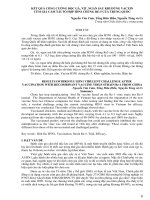
In the field of precision machining or advanced manufacturing, especially in automobile manufacturing, the problem of burr is causing headaches for many experts. These are burrs left on the part surface after machining, appearing in processes such as turning, milling, drilling, and casting. These issues do not only reduces the accuracy of the part, but also burr removal process is often very much time-consuming and costly. Fig. 1.1 Shows particles extracted from transmission using 120 um grid filter.
<b>Fig. 1.1 Shows particles extracted from transmission by grid filter. </b>
Burr is the root cause of many serious problems inside the engine, transmission, and crankshaft. The inability to completely remove burrs has led to an increase in the number of auto recalls in recent times. These parts have common designs, including very small oil line systems created from drilling intersecting or inclined cross-section holes, cast surfaces, drilled holes combined with milled surfaces, and combined milled surfaces and the casting surface. In addition, in the engine and transmission, there are various types of sensors and solenoid valves to control oil pressure and motion signals. Burrs that are not cleaned thoroughly can detach out during engine operation, follow the lubricating oil, and easily stuck in locations such as oil lines, solenoid valves, and sensors, causing serious errors. When mixing with lubricating oil that is circulated through all parts in the engine, burrs/chip/cast particles created direct contact or strong impact into metal surfaces, creating negative effects on the surface or connection between parts. In particularly, when the car is running at high speed, the consequences can become more serious,
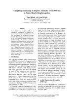
<b>affecting the working surface and the function of key components. Fig. 1.2 Cross-section </b>
of Intersection between casting surface and drilling holes of Automotive Transmission.
<b>Fig. 1.2 Intersection between casting surface and drilling holes of Automotive </b>
Transmission at control valve.
</div><span class="text_page_counter">Trang 14</span><div class="page_container" data-page="14">D. Dornfeld [1,2] defined the concept of Cleanability, which totally change the concept of DFM (Design for Manufacturing) to become DFC (Design for Cleanability), with the meaning to care much more about issues related to the final processes at manufacturing: deburring, cleaning, … then call back these designs, so that can change basically the cutting conditions, parameters of robot arm handling, controlling system, anodizing, and much more importance is the changing in the Design of original parts.
Particle Classification Algorithm, and Particle Expert System were generated by Phan Quoc Bao, Ko Sung Lim [3,4] to predict the main effects into the system were burrs, cast, chip, then propose the solution to improve the cleanliness. The results allowed users to identify particle origins after PCA parameter training and post-image processing. From there, they determine which particle is created by which machining step, which helps support the direction to solve that Particle. Especially, that can be possible to upload into web-based expert system to support worldwide users to upload their issues with particles similarity to these research. However, there were need a better database processing with ANN
In this research paper, we apply Artificial Neural Network combined with Genetic Algorithm (ANN_GA) to improve parameter optimization for the Particle Expert System (PES) classification algorithm. Therefore improving the accuracy of particle classification. Our researches showed promising to create a self-learning particle expert system that can recognize different particle types with at high speed and accuracy.
<b>1.2. The need for research </b>
The current automobile manufacturing industry, when using 6-speed engines, always finds hidden risks: sudden acceleration, loss of throttle, lack of throttle, breakage, damaged sensors, damaged control valves because particles are always present. are separated from the transmission system when we accelerate, under the compression pressure of gasoline and thrust when starting the engine, these particles are easily separated from the casting made from ADC12 aluminum alloy.
<b>Fig. 1.3 </b>SEM analysis of particles with chemical composition and surface structure. The high level of noise in the sharpness of images taken of Particles with the Burr Measurement System H.Phuong[5] led to the construction of input data for particles by Bao, Ko Sung Lim [3,4] limited to the range of 100-400 µm, in these areas it is very difficult for us to classify, calculate, and build a standard database for classification, so we use ANN artificial intelligence to advance Prediction combined with GA optimization algorithm as a development platform at the micro-scale level.
</div><span class="text_page_counter">Trang 15</span><div class="page_container" data-page="15"><b>1.3. The goal of the research </b>
− Improve the reliability of the classification algorithm on the platform developed with Taguchi from input from experts.
− Develop identification software for hardware of metal scrap sorting equipment, applied at the micro to nano size level.
− Build intelligent classification algorithms to integrate into production design software from the early stages of the production chain.
<b>1.4. The object and scope of research 1.4.1. The object of the research </b>
− Image of particles taken from inside car engines. − Algorithm for classifying particles.
− Optimized parameters for particle classification algorithm.
− ANN artificial neural network and reasonable optimization method.
<b>1.4.1. The scope of the research </b>
− Analyzing, calculating, simulating and optimizing parameters for the particle classification algorithm.
<b>1.5. Approach and research method 1.5.1. Approach </b>
− A classification algorithm with new parameters and a particle identification system created by inheriting the old classification algorithm have been enhanced ability to detect particles in sizes from micro to nano.
− Optimize parameters for classification algorithm using Artificial Neural Network ANN and genetic algorithm GA.
<b>1.5.2. Research methods </b>
− Theoretical reference method.
− The method of inheriting the research has been made. − Methods of analysis and evaluation.
− Computational research methods.
− Programming and simulation using Matlab and Python software.
<b>1.6. Project results </b>
<b>− Description: </b>
• Classification algorithm with optimized parameters using ANN-GA.
• The particle classification system is based on an optimized classification algorithm
• Document the analysis results and set of parameters as the basis for the international article.
<b>• The new classification method uses a boundary matrix to identify Particles. </b>
<b>1.7. Efficiency specification </b>
<b>− Aspect of education and training: The results of this research build a foundation </b>
for international articles, research documents for students with passion in the field of cleanability or research on classification algorithms.
<b>− Aspects social and economic: Developing software for hardware devices to </b>
classify particles at the micro to nano scale, improving efficiency in automobile manufacturing. Integrate intelligent sorting algorithms into design software in the first stages of the production line to identify and minimize particle sources, optimize production costs for deburring, and accelerate production green and improve production efficiency.
</div><span class="text_page_counter">Trang 16</span><div class="page_container" data-page="16"><b>CHAPTER 2: BASIC THEORIES 2.1. Cleanability problems and technology. </b>
<b>2.1.1. Introduction </b>
Cleanability is defined as the ratio between the level of cleanliness obtained and the amount of cleaning effort or resources invested, would involve the totality of stages that comprise the design-to-manufacturing cycle, since cleanliness depends on decisions made from early product conceptualization through finishing operations, Fig. 2.1.
<b>Fig. 2.1 Cleanability in the design-to manufacturing cycle and main influences [1] </b>
Level I: Cleanability should be concerned at design process. We could have many different choices to select the geometric parameters to satisfy the requests of design for manufacturing and design for cleanability as well, Fig. 2.2.
<b>Fig. 2.2 Design of intersection holes considering cleanability[3] </b>
Level II: Selecting the method of manufacturing is very important to solve cleanability problem. At this stage, we could predict the type of particles which can be generated, such as casting debris from casting technology, chips from machining process, unstable burr which was detached out of burr after high pressure water jet (HPWJ).
Level III: After selecting the suitable manufacturing processes, we move deeply inside the micro planning processes, e.g chip optimization, burr minimization…
</div><span class="text_page_counter">Trang 17</span><div class="page_container" data-page="17">
<b>Fig. 2.3 Chip morphology, formed by drilling & milling [2] </b>
The cleanability must be related to the optimal chip geometry like chip size, shape, mechanism of chip generation, as shown in Fig. 2.3. We could control the chips shape by controlling the cutting parameters [2].
Level IV: It becomes very limited for any change in cleaning processes. If we only keep concentration into level IV without doing careful researches from level I, II, III, it becomes too late to solve problem related to cleanability.
In automotive production, the processing of cylinder heads, valve body transmission, and crankshafts induces risk to reliability just because of the appearance of particles inside. These mechanical products have coolant networks and oil channels inside. Moreover, they also have many other different type of equipment such as sensors, and valve control equipment,… When particles travel into these areas, they become incredibly challenging to remove.
<b>2.1.2. Advanced cleaning methods </b>
Many cleaning methods, such as high-pressure water jets (HPWJ), flow cleaning, and brushing, were found ineffective for removal. Particles cannot be transported out of the part. It could scratch on precision surfaces, wear and lead to malfunction. Fig. 2.4 shows particles trapped in transmission valve control and broken crankshaft.
The particle could damage the working function of the magnetic valve control, which could result in the loss of control of the car. In another scenario, this particle can be lodged between the auto transmission valve body and the movement shaft inside the transmission, Fig. 2.4(b). It could stop the oil flow inside the transmission and prevent on-time oil supply to the different controlling functions inside. In one case, the crankshaft bearing broke because of the presence of small particles between the crankshaft and bearing during car operation. These particles could come from machining chips and poor surface casting or machining on the crankshaft, Fig. 2.4(a).
</div><span class="text_page_counter">Trang 18</span><div class="page_container" data-page="18"><b>Fig. 2.4 Real industrial cleanability problem in automotive </b>
As the tolerances required for mechanical instruments become increasingly small, the requirements for contamination become more stringent. Specifically, the research reported in this thesis is geared toward the problems of cleanliness associated with transmission valve bodies. These components are currently cleaned inefficiently, such as ultrasonic systems used to loosen chips, blasting with water jets from all directions, deburring by brushing the part in different directions, and even using many workers to deburr the part manually.
<b>2.1.3. Deburring Processes and Cleanability </b>
The high-pressure water jet (HPWJ) is an efficient cleaning method and an effective deburring process. HPWJ at 500 – 550 bar is the most effective at removing embedded and jammed particles from the workpieces while incurring very low residual stresses and damage to the surface [3]. However, regarding cleanability, HPWJ may be the main reason behind the creation of many particles that could lead to contamination-related failures, Fig. 2.5.
<b>Fig. 2.5 Morphology of surface after different deburring processes </b>
</div><span class="text_page_counter">Trang 19</span><div class="page_container" data-page="19"><b>Fig. 2.6 Burrs at different locations after HPWJ & Brushing </b>
The surface morphology before deburring was very rough because of the casting preparation, especially in the area between the drilling and casting surface. It could create many areas inside the transmission that are prone to damage. When deploying HPWJ, these areas were enlarged and generated many more particles.
The secondary particles become more challenging to control as the shape and the source are complex. Another deburring method, peening vibration, was used to solve the problem related to surfaces after casting. However, the impact of metal balls on the casting surface can induce residual stress on the surface and simultaneously create micro cracks.
With HPWJ and brushing, burrs were found to remain, which include stable burr and unstable burrs. The particles can be generated from unstable burrs, Fig. 2.6.
<b>Fig. 2.7 Burr at window after HPWJ and brushing </b>
In addition, burrs remained at the window areas of the transmission. At these locations, burr could prevent the flow of the oil and water line. Under these windows, a shaft moves up and down during car operation, and the gap is very small, even smaller than the size of particles. As a result, the particles could be lodged inside and damage the transmission, Fig. 2.7.
Brushing is one of the most efficient processes for finishing and deburring machined parts in automotive production. This process removes the defects on the surface and the intersection areas between casting and machined parts after the high impact of the water jet process. The burrs and edges in the rotating direction of the brush can be well treated. The burrs formed along the edge that is perpendicular to the feed direction are very difficult to remove.
</div><span class="text_page_counter">Trang 20</span><div class="page_container" data-page="20"><b>CHAPTER 3: CHARACTERIZATION AND RECOGNITION OF PARTICLES FOR IMPROVING CLEANABILITY IN AUTOMOTIVE </b>
<b>PRODUCTION 3.1. Mechanism of particles generation </b>
In his research, Phan Quoc Bao and Ko Sung Lim [3] concentrated on identifying burrs and cast particles forming on window areas and casting surfaces. Their study, illustrated in Fig. 3.1, highlights four critical zones within a transmission component for examination, including the cast and machined surfaces, the junction between them, and
<b>the edges during drilling and milling operations. The creation of burrs is attributed to the </b>
plastic deformation that occurs at the end of cutting processes such as milling and drilling, where they appear as residual chips on the workpiece. Gillespie [6] categorized burrs into four types based on their formation mechanisms: Poisson, rollover, tear, and cut-off burrs. Additionally, Chu and Dornfeld [7] identified exit burrs, which form along the edges as the tool exits the workpiece. Filters capture burrs that detach from the workpiece during machining in transmissions or engines, distinguishing between unstable burrs, which are removed post-machining or deburring, and stable burrs, which are tolerable if they do not interfere with functionality. Assessing the formation of unstable burrs is crucial for their characterization.
<b>Fig. 3.1 Samples with 4 areas: casting surface, machined surfaces (drilling and milling), </b>
window area between casting surface and machined surface, and edges at point 7 and point 8.
</div><span class="text_page_counter">Trang 21</span><div class="page_container" data-page="21"><b>Fig. 3.2 Stable burrs formed along the edge of a workpiece even after deburring process, </b>
location 2 and 3, in Fig. 3.1.
<b>Fig. 3.3 Unstable burr after machining or deburring process </b>
</div><span class="text_page_counter">Trang 22</span><div class="page_container" data-page="22">Stable and unstable burrs formed at the interfaces of cast surfaces and drilled holes, as depicted in Fig. 3.2 and Fig. 3.3, respectively. Stable burrs, identified at these junctions, persist through operational use, a feature highlighted in Fig. 3.2. The study notes a risk of damaging these surfaces through the intensification of high-pressure water jet treatments or alterations to the feed rate of jet nozzles and brushing durations. Such treatments, aimed at minimizing burr size, also risk generating additional particulate matter, emphasizing the delicate balance required in these processes.
Conversely, Fig. 3.3 illustrates unstable burrs prone to detachment during operation, contributing to particulate contamination in circulating oil flows. Particularly, Fig. 3.3(a) reveals a window burr at a drill entry, bending as the drill progresses, a phenomenon that underscores the variability in burr stability and the critical role of brushing in particle removal. The parameters of brush material, along with the diameters of the brush and its filaments, are under scrutiny for their efficacy in this context.
Further complicating the issue, Fig. 3.3(b) presents a feed direction burr, common in deburring research yet notable for its formation at the intersection of casting and drilling. This interface harbors both stable and unstable burrs, with removal strategies differing based on burr stability. The narrative extends into Fig. 3.3(c), where a window burr at a drill exit is discussed, reinforcing the potential for deburring through optimized brushing conditions.
The challenges of burr removal are not uniformly surmountable across different burr types. As evidenced in Fig. 3.3(d), stable burrs at the juncture of milled and cast surfaces resist removal methods, including high-pressure water jets and brushing, a limitation deemed acceptable within the operational context. However, this acceptance does not extend universally, as illustrated by the precarious situation of machined and cast surface intersections described in Fig. 3.3(e). These areas are notably vulnerable, with unstable edges easily compromised by high-pressure treatments, underscoring a critical concern in surface treatment practices.
This intricate exploration of burr dynamics, detailing both the challenges and strategies for managing burr formation and removal, provides a foundational basis for this capstone project. The distinction between stable and unstable burrs, alongside the methodologies employed to mitigate their impact, encapsulates a critical aspect of surface treatment that warrants thorough examination.
</div><span class="text_page_counter">Trang 23</span><div class="page_container" data-page="23"><b>Fig. 3.4 Generation of cast debris and cast surface </b>
<b>Cast Particles: In the metal casting process, it's noted that irregularities, known as </b>
casting defects, occur and are undesirable. These defects are categorized into five main types: gas porosity, shrinkage defects, material defects, pouring metal defects, and metallurgical defects[8]. After cleaning with a high-pressure water jet, small particles,
<b>called casting debris, remain on the surface as shown in Fig. 3.4(a). This cleaning </b>
method, while effective, may further fragment small casting defects, leading to the creation of these particles. Although a significant portion of these particles are removed during the cleaning process, a residual amount remains, either within the defects or on the surface, posing a challenge for achieving a perfectly clean cast surface.
Large surface defects in casting, as depicted in Fig. 3.4(b), also produce invisible casting particles. These defects have a substantial likelihood of partial detachment during the cleaning and deburring process, utilizing high-pressure water jets. The impact of such
<b>jets on these compromised cast surfaces generates thin and extensive cast particles, as </b>
illustrated. Typically, these particles are irregular in shape and black, highlighting a crucial aspect of the casting process. Ensuring the minimization of cast defects becomes imperative from a cleanability standpoint. This observation underscores the importance of reducing defects to prevent the formation of such particles, thus enhancing the overall quality of the cast product.
</div><span class="text_page_counter">Trang 24</span><div class="page_container" data-page="24"><b>Fig. 3.5 Variety of chip shape </b>
<b>During the processes of machining, such as drilling or milling, chips of various </b>
shapes are generated, including discontinuous, wavy, sawtooth, continuous, segmented, serrated, or sheared. It was found by Corinne L. Reich-Weiser [9] that manipulating process parameters like feed, speed, depth of cut, and lubrication can optimize the chip types produced. This optimization offers insights into the impact of these parameters on chip geometry and size. Although chips are typically removed during machining and deburring, their specific geometries sometimes prevent complete removal.
Show in Fig. 3.5 are several common chip shapes, where some display serration marks on their surfaces, while others are characterized by smooth, curled, or flat appearances. Large chips tend to become lodged in trap positions, potentially causing significant internal damage. In the quest to enhance cleanability, S.Garg, D.Dornfeld, and K.Berger [10] explored the relationship between chip morphology and the workpiece landscape, leading to the development of a chip optimization model. This model has proven instrumental in addressing industrial cleaning challenges, particularly for transmissions and automotive cylinder heads. Additionally, Corinne Lee Reich-Weiser [2] delved into strategies for controlling chip-related contamination by varying cutting parameters such as feed, speed, depth of cut, and lubrication, contributing to the body of knowledge on maintaining clean machining environments.
<b>3.2. Standard for particle classification </b>
The standards of particles can be summarized as followed based on the formation mechanism Phan Quoc Bao, Ko Sung Lim [4]:
<small>Burr 1 Burr 2 Burr 3 Burr 4 Burr 5 </small>
<small>These very long particles are generated along an edge with radius Ra of a drilled hole and a straight particle along an edge in milling. </small>
<small>These are mostly long and thin shape. They are generated along the edges of a smaller radius Rb or from a burr of the milling surface. </small>
<small>These also have a long shape. They are generated from the edges of a smaller radius Rc or detached from a milling burr (Ra>Rb>Rc). </small>
<small>These short particles are generated along an edge in drilling and milling, as part of burr 3 that is broken partly in the deburring process. </small>
<small>The smallest burrs are generated from unstable burrs that are detached from existing burrs. </small>
</div><span class="text_page_counter">Trang 25</span><div class="page_container" data-page="25"><small>Cast surface 1 Cast surface 2 Cast surface 3 Cast surface 4 Cast debris </small>
<small>These cast particles are detached from weak surfaces during machining and deburring. Mostly, they are very large and thick. </small>
<small>These wide and thin particles are generated from a casting surface defect during the deburring process that is enlarged by a high-pressure water jet. These small and thin particles are detached from casting surface defects on the surface near the edge between the machined and cast surface </small>
<small>These small and thin particles are detached from casting surface defects mainly at the edge between the machined and cast surfaces. </small>
<small>These small particles are generated from the defects of the casting surface during the deburring process. </small>
<small>Chip Most chips are larger than other particles </small>
<small>Filament of brush These are broken off during the brushing process when filaments contact sharp burrs, rough edges, or surfaces. </small>
<b>Table 3.1 Classes of particles in PCA[4] </b>
In analyzing particle parameters, noise was eliminated from particle images using image processing, and boundary features were identified. This established a classification standard, depicted in Fig. 3.6, for distinguishing particle types.
<b>Fig. 3.6 Standard of particle classification after image processing to get clear shape/boundary of </b>
particles
<b>Fig. 3.7 Definition of shape parameters in (a) burr, (b) cast, (c) chip and (d) filament of brush </b>
</div><span class="text_page_counter">Trang 26</span><div class="page_container" data-page="26">Fig. 3.7 introduces the shape parameters critical to the particle classification algorithm. Length (L) and width (W) are foundational measurements, with L representing the longest line within the particle and W measured perpendicularly to L. This framework facilitates the precise characterization of each particle's geometry.
To simplify classification, three independent parameters length (L), width (W), and the real area (A, represented in white) are complemented by the aspect ratio (R = W/L) and the area ratio (AR = A/(L*W)). These parameters offer a comprehensive basis for distinguishing between different particle types, enhancing the algorithm's ability to classify accurately.
The classification process is streamlined through an automated measurement system, allowing for the efficient measurement of these five parameters for each particle. Data is cataloged in Excel, supplemented by manual particle classification to ensure accuracy. The establishment of boundary values for these parameters facilitates the identification of critical values, effectively differentiating between particle types. This methodological approach ensures a high degree of precision in particle classification.
<b><small>Decision </small></b>
<b><small>Max Length (L) </small></b>
<b><small>Max Width (W) </small></b>
<b><small>Area Aspect Ratio (AR) </small></b>
<b>Table 3.2 Automatically measured shape parameters (L, W, A) of sample particles[4] </b>
The analysis documented in Fig. 3.7 and Table 3.2 presents the outcomes from particle image processing, where noise within the boundaries is removed. This detailed examination reveals that five key geometric parameters effectively differentiate between burrs, cast particles, and chips, providing a basis for their classification.
<b>3.3. Algorithm of classification </b>
In a research work Phan Quoc Bao, K.S.Lim[4], a sophisticated algorithm was developed to categorize 12 distinct classes of particles, amassing over 3000 specimens from various abrasive processes using high-pressure water jets. These particles were primarily derived from transmission systems, engines, and crankshafts. Building upon the foundations laid by the previous Particle Classification Algorithm (PCA) [3], this research introduced new initial parameter values (P0)1, detailed in Table 3.6. Additionally, a second set of initial parameters, (P0)2, was proposed for more in-depth analysis and exploration.
</div><span class="text_page_counter">Trang 27</span><div class="page_container" data-page="27">To obtain the results in table 3.6, the author used the taguchi and Anova methods with specific parameters to select the appropriate orthogonal array for testing 7 factors with 2 levels. The primary goal was to meticulously analyze the measurements and success rates of the trials, emphasizing factors that significantly impacted the success rate (SR) and scrutinizing each parameter. The response parameter was the success rate, and two distinct randomization groups were employed in the simulations. To assess the factors' influence on the output results, the Minitab software was utilized to apply experimental planning according to the Taguchi method. Optimal factor values were determined, and the objective function was recalculated accordingly. Subsequently, these values were experimentally tested, and the results are detailed in Table 3.3.
From the Taguchi results, an optimal value was chosen for each variable. The remaining variables were ranked based on their contribution, with R1 demonstrating the highest contribution at 38.71%, followed by L2 at 20.97%, and L3 at 12.90% (as illustrated in Table 3.4). From this result, the author focuses on the 3 parameters with the highest influence and begins to search for values close to the designed parameters in Table 3.3 to find the set of 3 parameters with the highest SR%. Finally, the authors were also able to achieve classification at the final values shown in Tables 3.5, with a success rate of up to 98% for group 1 and 94.40% for group 2.
<b>Table 3.3 L-8 experiments, with 2 trial test results from group 1, 2[3] </b>
<b>Table 3.4 Proper value from ANOVA[3] </b>
</div><span class="text_page_counter">Trang 28</span><div class="page_container" data-page="28"><b>Table 3.5 Final values of variables R1, L2, L3[3] </b>
<b>Table 3.6 Initial values of algorithm parameters[4] </b>
The success rate of the classification with this new algorithm (P0)<small>1</small> is 91.9% with 1000 particles. In addition to deploying a new image-processing algorithm with a deeper understanding on the mechanisms of particle generation, the particle classification algorithm was improved with a new model with twelve different classes as shown in Fig. 3.8. The new particle classification algorithm classifies burrs into five classes, casts into five classes (including cast debris), and one class each for chip and brush.
<b>Fig. 3.8 Schematic illustration of Particle Classification Algorithm (PCA)[4] </b>
However, when the author uses the taguchi method to optimize the parameters, then compares the effectiveness of the parameters to select the parameters with the greatest influence and starts searching for neighboring parameters. . Therefore, these parameters have not been fully optimized. So there is a need for a better optimization method that checks all the parameters to avoid suboptimal results. In this research I will integrate Artificial Neural Network (ANN) and Genetic Algorithm (GA) to enhance parameter
<b>optimization for Particle Classification Algorithm (PCA). </b>
</div><span class="text_page_counter">Trang 29</span><div class="page_container" data-page="29"><b>CHAPTER 4: INTEGRATING ANN-GA INTO THE CLASSIFICATION ALGORITHM </b>
<b>4.1. Introduce ANN-GA </b>
<b>4.1.1. Artificial Neural Network (ANN) </b>
ANN stands for "Artificial Neural Network." It is a computational model designed to simulate the functioning of the human brain, particularly its ability to learn and perceive. Artificial Neural Networks are constructed from artificial neuron units connected to each other through weights. Each artificial neuron typically takes input, performs a weighted sum operation, and passes the result through an activation function to generate the output. ANNs have found widespread applications in various fields, including image recognition, natural language processing, data prediction, and many other applications. Artificial Neural Networks can learn from data and adjust their weights to optimize performance in specific tasks.
In the realm of artificial neural networks, the choice of network architecture is crucial and varies according to the problem at hand. It's up to the decision-maker to select the most appropriate network structure based on the specific problem requirements. This research employs the Multilayer Detection Model (MDM), which is notably favored for tasks such as classification and prediction due to its effectiveness in handling such problems.
The MDM model utilizes the backpropagation algorithm, which facilitates the learning of complex, non-linear relationships between process parameters through the use of artificial neural networks that include hidden layers[11]. These networks are composed of artificial neurons that replicate the function of biological neurons, forming a tri-layer structure consisting of input, hidden, and output layers[12]. During the training phase, it is essential to fine-tune the network weights to achieve accurate outputs[13].
The learning mechanism of the MDM network is an extension of the Delta Learning Rule, which is derived from the least squares method. The backpropagation's delta rule emphasizes continuous adjustment and refinement of the weights (i.e., the input connections) to minimize the discrepancy between a neuron's actual output and its intended output[14]. The learning process involves presenting vectors corresponding to target outputs to the network, with weight adjustments being made according to this specific learning rule[15]. Fig. 4.1 shows the input values xiand the weights wnj that determine the importanceof the inputs in the artificial neural network. Each entry and its weight are multiplied andall these values are summed to obtain a number. An activation function is used to makethis number between 0 and 1. Although there are many activation functions, the use of sigmoid function is common.
Unlike traditional statistical approaches, artificial neural networks do not impose preliminary assumptions on the dataset[16]. They are particularly beneficial in scenarios involving non-linear, multidimensional, complex, uncertain, incomplete, or flawed data, especially when there is no existing mathematical model or algorithm to address the issue. This flexibility and adaptability make artificial neural networks a powerful tool in a wide range of applications.
</div><span class="text_page_counter">Trang 30</span><div class="page_container" data-page="30">The research of integration of ANN by Minh Thuan Tran, Huy Tuan Pham, Quoc Bao Phan [17] showed the progress to develop the Particle Classification based ANN-GA, showed as below:
<b>Fig. 4.1 Basic working mechanism of neural networks </b>
MATLAB, a high-level programming language and interactive environment developed by MathWorks, provides extensive support for creating, training, and simulating neural networks through the Neural Network Toolbox Fig. 4.2. This toolbox is designed for both beginners and advanced users, providing a variety of tools to effectively create neural network models. These include the functions of designing network architecture, preprocessing data, dividing data into training, validation, and testing sets, training networks, and evaluating their performance. The toolbox supports many different types of networks, including feedforward, radial basis, dynamic and convolutional neural networks.
<b>Fig. 4.2 MATLAB's Neural Network Toolbox </b>
Getting started with ANN in MATLAB involves defining the problem, preparing the data, choosing the appropriate neural network model, training the model, and then testing and validating its performance. MATLAB simplifies these steps with a user-friendly
</div><span class="text_page_counter">Trang 31</span><div class="page_container" data-page="31">interface and comprehensive documentation, in addition to functions that automate much of the process. For example, nftool and nnstart are graphical tools in MATLAB that guide users through the neural network design and training process without requiring deep programming expertise.
<b>4.1.2. Genetic Algorithm (GA) </b>
The genetic algorithm (GA) is another optimization technique that draws its analogy from nature. The process of natural evolution intrigued John Holland of the University of Michigan in the mid 1960s. He developed computational techniques that simulated the evolution process and applied to mathematical programming. The genetic algorithms revolve around the genetic reproduction processes and “survival of the fittest ” strategies.
Genetic algorithms follow the natural order of attaining the maximum. The problem for GA will be posed in the form
maximize <i>f (x) </i>
subject to <i>li ≤ xi ≤ ui ; i = 1 to n </i>
Principles of Genetic Algorithms(as shown in Fig. 4.3)
Population: GA operates on a population of potential solutions, each represented by chromosomes (typically strings of binary values, although other representations are possible).
Fitness Function: Each solution is evaluated to determine how "fit" it is, usually by how well it solves the problem at hand. The fitness function is crucial as it guides the evolutionary process.
Selection: Solutions are selected for reproduction based on their fitness. The fitter the solution, the higher its chances of being selected, emulating natural selection.
Crossover: Selected solutions are recombined to produce offspring, which inherit characteristics from both parents. This process is inspired by biological crossover and recombination.
Mutation: With a small probability, some parts of the offspring are mutated or changed. This introduces variability into the population, allowing the algorithm to explore new areas of the solution space.
Replacement: The least fit individuals in the population are replaced by the new offspring, moving the population towards better solutions over successive generations.
<b>Fig. 4.3 Simple diagram explaining the GA algorithm </b>
</div>