report technical writing and presentation topic using lidar to approaches road boundary and obstacle detection
Bạn đang xem bản rút gọn của tài liệu. Xem và tải ngay bản đầy đủ của tài liệu tại đây (1.14 MB, 11 trang )
<span class="text_page_counter">Trang 1</span><div class="page_container" data-page="1">
<b>SCHOOL OF ELECTRONICS ANDTELECOMMUNICATIONS</b>
Instructor: TS.NGUYỄN TIẾN HOÀ
Hanoi, December 22, 2022
</div><span class="text_page_counter">Trang 2</span><div class="page_container" data-page="2">b. Positioning the LIDAR sensor on the Vehicle...6
c. Approaches of the Detection of Road Boundaries...7
d. Approaches of detection of obstacles...9
5. CONCLUSION...10
6. REFERENCES...10
7. TABLE OF FIGURE...11
</div><span class="text_page_counter">Trang 3</span><div class="page_container" data-page="3">1. Abstract
The self-driving cars vehicle reduce the driver’s need and is subsequentlysuitable for people, such as older people, children, or individuals withdisabilities, who are unable to drive. Self-driving cars are developing rapidly toimprove the driving safety and transportation efficiency. Self-driving cars arequalified in many scenarios that are dangerous, inconvenient for human drivers.One of the essential problems of self-driving technology is how to achieve high-precision pose of self-drivingcars, which leads to the development of self-driving cars. This report introduces an overview of the studies of two problems;(1) road boundary detection and (2) obstacle detection, in order to allow themovement of autonomous vehicles. Light Detection and Ranging (LIDAR) isthe most used technology for solving these two problems.
Keywords: self-driving car, Lidar, road boundary detection, obstacle detection,autonomous vehicles.
2. INTRODUCTION
Transportation accidents are in an exceedingly one amongst the numerouscauses of death in a world . According to the report unconcealed by the “WorldHealth Organization (WHO)”, over one million fatalities are caused due to roadaccidents and the numbers are even a lot of which incorporates very little ormajor injuries. Most of the time accidents happen because of human mistakes.Humans attempt mistakes in numerous ways, such as using mobile phones whiledriving, not following traffic rules, distracted through billboards and deficiencyof sleep results in drowsiness generally while driving. Consequently, in responseto the above-mentioned conditions accidents occur. Therefore, there is a needfor a solution that helps humans in safe driving.
The tale of Self-driving automobiles began in the Nineteen Twenties. Once thefirst guided car was introduced, leading to more enhancement and improvementin cars. Further, the vision guided car was introduced in 1988 with the use ofLIDAR and computer vision for tracking and obstacle detection and prevention.This project was funded in the US by the DARPA using emerging technologies.For around 20 years, “Uber”, “tesla”, “google”, “Toyota” are some of themanufacturers that have been designing and testing these cars and they hadachieved good results while moving towards complete automation. A self-driving car can make more efficient use of car transportation and improveservice to disabled individuals.
Self-driving car have been designed in different countries. Some of theprototypes have participated in an Urban Challenge competition which washosted by the Defense Advanced Research Projects Agency (DARPA) in 2003in U.S.A. An example of autonomous vehicle, Boss, was the winner of thecompetition; it was designed by Carnegie Mellon University [1]. Considering
</div><span class="text_page_counter">Trang 4</span><div class="page_container" data-page="4">that most accidents are human-induced, more intelligent vehicles can reduce therate of accidents and improve energy efficiency by maintaining the optimumlevel of fuel consumption. There are a number of problems that need to besolved in autonomous vehicles. Some of these problems are: route planning,precise positioning, detection of traffic lights, sensing traffic signs, obstacledetection and identifying the boundaries of roads. The most important of theproblems is the detection of obstacles and road boundaries as this plays a vitalrole in the safety of the drivers, animals and passengers in traffic. There aremany methods and sensors in autonomous vehicles for the detection of the roadboundaries and obstacles. Typical examples are cameras and image processingtechniques, sensitive radars, ultrasonic sensors and LIDAR. Cameras and imageprocessing techniques have long been used as a research topic because camerasare cheap devices and easy to supply compared with sensors [2]. Cameras are arelatively old technology and carry high-resolution information which hasresulted in a great deal of successful work [3].
Using sound-based ultrasonic sensors are another method of obstacle detection.Ultrasonic sensors send out high frequency sound signal and evaluate the echowhich is received back by the sensor. The time interval between sending thesignal and receiving it back is calculated to determine the distance to an object.In this method, the sound signal expands like a funnel and shrinks back. Hence,any changes that are smaller than the track of the signal propagation cannot bedetected. It may not be possible to know and predict much about the shape ofthe obstacle detected. On the other hand, some of the obstacles do not reflectback the sound signal but absorb it instead. Because of that, detecting suchobstacles might not be feasible with ultrasonic sensors because it renders theminadequate and unsafe in this circumstance. Currently, they are mostly used as awarning system for parking.
Another technology used in detecting obstacles is radar systems. Radars candetect distant objects and are not affected by the weather conditions and theamount of light [4]. The principle of the radars is similar to that of ultrasonicsensors. Unlike ultrasonic sensors, however, they send out radio signals. As inultrasonic sensors, based on time difference between the radio signaltransmission and reception, the distance from radar to an obstacle is estimated.There are two type of radar in land vehicles: short-range radars which operate at24-Ghz wavelength and long-range radars which operate at 77-Ghz wavelength[5] [6].
Recently, LIDAR sensors have been used as one of the main technologies indetecting objects. The principle of LIDAR sensors is similar to that of radarsand ultrasonic sensors but they use laser to measure the distance. After a laserbeam sent from a LIDAR hits an object, it reflects back to LIDAR. The distancebetween the LIDAR and the object is calculated as follows: the round-tripduration of the beam is multiplied by the speed of the light, then the result isdivided by 2, the final result represents the distance. Resolution of the LIDARsensors is high as they use laser technology. They would have high accuracy
</div><span class="text_page_counter">Trang 5</span><div class="page_container" data-page="5">when image processing techniques are insufficient due to the weatherconditions. However, they seem to be more expensive when compared with theother types of sensor.
3. PROBLEM DEFINITION
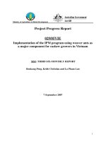
Autonomous vehicles are expected to stop instantly or find an alternative way inorder not to damage when they detect an obstacle. Examples of the obstacles arevehicles, pedestrians and potholes on the road, speed bumps, sidewalks andbarriers at the edge of the road. Figure 3.1 shows an example road environmentin which the road is bordered by shrubs and open ground. Also, there is a bargein the middle of the road. The problem in this situation is to detect the boundarylines of the road and find an appropriate route for the vehicle. Let us call thearea on the right-hand side of the barge A and the area on the left-hand side ofthe barge B. An autonomous vehicle is expected to choose either A or B in orderto avoid crashing into the barge. This study focuses on the finding a route forvehicle to detect the obstacles on the road and pass through safely.
4. ROAD BOUNDARY AND OBSTACLE DETECTIONAPPROACHES
a. Lidar Sensors
LIDAR sensors are used for many purposes in industry. Some typical areas ofuse are: measuring the density of particles in the air (rain, fog, nitrogen-oxygenratio and wind speed), making three-dimensional topographic maps and pictureof works of art, obtaining seismic data, obtaining information about the surfaceof Mars, analysis of the ocean floor and detecting obstacles for autonomousvehicles. This paper studies the published research on the use of LIDARsensors for autonomous vehicles.
LIDARs are used for detecting obstacles and producing detailed information
<small>Figure 3.1. An example road: with a barge in the middle of the carriageway, shrubs and lighting</small>
</div><span class="text_page_counter">Trang 6</span><div class="page_container" data-page="6">about the obstacles in very high- resolution. For example, the resolution of theSICK LMS-511 LIDAR is around 0.167 degrees and the fault tolerance in 80meters is around 30-40 mm. They provide high resolution even in the case ofbad weather conditions.
A common problem for lasers is that black-colored obstacles absorb the lightand only weakly reflect the signal. Some of the LIDAR sensors can tolerate thisproblem. For instance, the LMS-511 sensor produced by SICK; its range forblack- colored obstacles is 26 meters while its 80 meters in others. The range ofa LIDAR sensor with a 190 degree scan angle is shown in Figure 4.2.
There are three types of LIDAR sensor: one-dimensional (1D), two-dimensional(2D) and three-dimensional (3D). One-dimensional (1D) lasers work like lasermeter which provides distance from a point to the meter. 2D LIDAR sensors,according to their scanning angles, make a land scan and try to work out x and ycoordinates of a point. 3D LIDAR sensors comprise a set of 2D sensors. Theyanalyze the x and y coordinates of 2D sensors on the z axis.
LIDAR sensors are high-speed devices and generate information at 100Hz. Theamount of information generated in an autonomous vehicle using three or fourLIDAR sensors can reach to millions point levels. This high load of informationneeds to be processed in real-time by vehicle decision support system. Delaysand faults in processing the information can cause critical problems for themovement of the vehicle.
b. Positioning the LIDAR sensor on the Vehicle
The position of the LIDAR sensor on a vehicle is an important issue for thedetection of the obstacles and road boundaries. Figure 4.3 shows a vehiclewhich has a 2D LIDAR sensor positioned on the top of the vehicle and alignedparallel to the ground. Let us assume an inclination angle of 0 degrees and aground height of h cm in this position. In this case, only obstacles which have a
<small>Figure 4.2 An example of 2D LIDAR sensor.</small>
</div><span class="text_page_counter">Trang 7</span><div class="page_container" data-page="7">height of h cm or more can be detected. Two obstacles are shown in Figure 4.3,a yellow cylinder higher than h cm and a green cylinder lower than h cm aregiven as an example. The position of the green cylinder cannot be detected whilethe yellow cylinder is detected. If the LIDAR sensor is placed in a lowerposition, the green cylinder can be detected. However, speed bumps andpotholes on the low level of the ground cannot be detected. For these reasons,LIDAR sensors must be aligned at an angle, sloping downwards. Figure 4.4shows an example of a LIDAR sensor positioned with an angle.
<small>Figure 4.3. 2D LIDAR sensor with scan angle of 180 degrees</small>
<small>Figure 4.4. 2D LIDAR sensor with an inclined degree of an angle.</small>
Han et al designed a vehicle using LIDAR sensor with a downwards-slopingangle [7]. Their vehicle won first place in the 2010 Autonomous VehicleCompetition (AVC). Similarly, Wijesoma and his colleagues designed a vehiclewhich can reach known targets [3].
There are number of disadvantages of positioning LIDAR with a sloping angle. When the first scan of LIDAR sensor starts an area under thescan, in front of the vehicle, is not covered. There might be an obstacle in thisarea which may cause problems even though it is not very likely. To alleviatethis probability, Han et al. used two LIDAR sensors, one with a sloping angleand one parallel to the ground.
downwards-c. Approaches of the Detection of Road Boundaries
In this study i introduce two new terms: physical road boundaries and logicalroad boundaries. Edge points of the road on which traffic flows and includescrosswalk, traffic lights is defined as physical road boundary. On the other handlogical road boundaries are calculated by taking obstacles into account. It is thepoints on a road where vehicle can pass through. and points represent the<b>EF</b>
physical road boundaries and and points represent logical road boundaries<b>CD</b>
</div><span class="text_page_counter">Trang 8</span><div class="page_container" data-page="8">in <b>Figure 4.6 E</b>. and points are not assumed to be logical road boundaries<b>A</b>
because the width of the vehicle is larger than the length of from to so that<b>EA</b>
the vehicle cannot pass through.
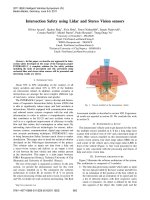
The main principle of detection of logical road boundaries using a LIDARsensor is to find more regular and larger planes to allow vehicles to go through.The term of ‘more regular’ refers to the linear changes of height, distance andinclination of the points that continuous laser beams reflect back. The mainfeature of algorithm of the Han et al.’s vehicle is that if the continuous laserbeams from the LIDAR sensor continue to stay on the same object then asmooth change on the measured distances is expected. If the measured distancedifference is beyond a given threshold then two consecutive laser beams arereflected by different obstacles. These two points are used as a breaking point inthe algorithm [7]. Figure 4.6 presents an environment with obstacles andphysical and logical road lines. The black points show the breaking points.According to the LIDAR beams shown in Figure 4.5, if the distance betweenthe consecutive points (P1, P2) is beyond a threshold value and the tangent ofthe line through the two points is beyond a threshold value, P1 and P2 arebreaking points. To decide whether or not P1 and P2 are breaking points,Equation 1 and Equation 2 can be used (Kang et al., 2012). Equation 3 andEquation 4 have been used to decide breaking points in [3]. The value of d<small>i+2</small> isthe measured distance between P3 and the LIDAR. If the consecutive LIDARsensor beams reflect back smoothly, with the distance information of the twopoints previously known and LIDAR's resolution degree, the position of a thirdpoint can be estimated using Equation 3 das .<small>p</small>
Also, if the difference in the value of in d<small>p</small> Equation 4 and measured d<small>i+2</small> isbeyond a pre-determined threshold value, this is a breaking point [3].
</div><span class="text_page_counter">Trang 9</span><div class="page_container" data-page="9">The ground height of the LIDAR sensor is , the sensor slope with the ground isha and the resolution is The reflection points of beams are γ. <b>P1 P2 and </b>, <b>P3</b>. The coordinates of the reflection points are (x<small>i</small>, y<small>i</small>), (x<small>i+ 1</small>, y<small>i+ 1</small>) and (x<small>i+ 2</small>, y<small>i+ 2</small>) respectively. The distances from the reflection points to the sensor are , d<small>i</small> d<small>i+1</small> andd<small>i+2</small>.
I call the set of points between the two breaking points a ‘segment’. From A toB, B to C and C to D are segments in Figure 4.6. Han, Wijesoma, Kang, Qinand Kim have divided the breaking points into segments. Later, the angle ofgradient of the segments and the ground height of the segments based onLIDAR sensor’s position are considered in deciding whether there is a segment
or not.
d. Approaches of detection of obstacles
One of the main problems to be solved in autonomous vehicles for safe drivingis to map obstacles around the vehicle. If GPS with high accuracy performspositioning, the obstacles in the map can be shown in their real locations(latitude/longitude). If there is no accurate GPS, the obstacles’ position can beshown relative to position of LIDAR. Another property that should be in themap is to show the type of the obstacles and the level of the danger which theypresent. The type of an obstacle refers to a mobile or a static state. The level ofdanger is determined by obstacle type. These levels can be classified asdangerous, low dangerous, safe and blind spot [8]. A blind spot is a place thatcannot be scanned by the LIDAR sensor.
<small>Figure 4.5. LIDAR sensor aligned with a sloping angle and notations used in formulas.</small>
<small>downwards-Figure 4.6. Road pavements and laser beams propagation with some obstacles</small>
</div><span class="text_page_counter">Trang 10</span><div class="page_container" data-page="10">To map obstacles, there are six steps to be done:
<small>I.</small> Breaking points are found.
<small>II.</small> Segments are obtained from the breaking points found.
<small>III.</small> Logical road segments are produced from the segments.
<small>IV.</small> After subtraction of the logical road segments, the rest of the segments areobstacles segments. They are compared with the obstacles found in theprevious map. If the location of the obstacle has changed, the obstacle ismobile, if not the obstacle is static.
<small>V.</small> The obstacle segments identified are placed into the obstacle map. Theobstacles passed by the vehicle are removed from the map.
<small>VI.</small> From the properties of the obstacle such as length and type, the level ofdanger is determined.
The final map is used in vehicle decision support.
5. CONCLUSION
In this study, the approaches in detecting road boundaries and obstacles usingLIDAR sensors and the advantages of the approaches have been evaluated.Some of the approaches were implemented in a VREP simulation environmentand the performances of the algorithms have been successful. There are still lotsof problems that need to be solved in autonomous vehicles. The currentperformances and reliabilities of the algorithms need to be further improved.
6. REFERENCES
[1] Urmson , C., Anhalt J. and Bagnell D. Other, Autonomous Driving in UrbanEnvironments: Boss and the Urban Challenge, vol. 17, Journal of Field Robotics, 2008.
[2] Choi, J., Lee J. and Kim D. Other, Environment-Detection-and-Mapping Algorithm for Autonomous Driving in Rural or Off-Road Environment, vol. 13, IEEE Transactions on Intelligent Transportation Systems, 2012, pp. 974-983.
[3] Wijesoma,W.S., Kodagoda K. R. S. and Balasuriya, A. P, Road-Boundary Detection and Tracking Using Ladar Sensing, vol. 20, IEEE Transactions onRobotics and Automation, 2004.
[4] J. Wenger, Automotive radar-Status and perspectives, IEEE Compound Semicond, 2005.
</div>