mini project construction organization design construction schedule and site logistics
Bạn đang xem bản rút gọn của tài liệu. Xem và tải ngay bản đầy đủ của tài liệu tại đây (3.28 MB, 47 trang )
<span class="text_page_counter">Trang 1</span><div class="page_container" data-page="1">
<b>FACULTY OF BUILDING AND INDUSTRIAL CONSTRUCTION Department of Construction Technology and Management</b>
--- ---
<b>MINI PROJECT</b>
<b>CONSTRUCTION ORGANIZATION Design construction schedule and site logistics </b>
</div><span class="text_page_counter">Trang 2</span><div class="page_container" data-page="2"><b>Department of Construction Technology and Management </b>
No 55 Giai Phong Road - Ha Noi - Viet Nam Tel: (84.4) 869 1684
<b>MINI - PROJECT ON CONSTRUCTION TECHNOLOGY 1 </b>
<b>DESI GN MONOLOTHIC REINFORCED CONCRETE CONS TR UCTION METHO D O F A MULTI-STOREY BUILDING </b>
Checking date Comments and Signature
<i><small>This table is only for the supervisor. </small></i>
120
Number of floor 4 / 5 / / 7 / 8 /9 Construction term Summer /
<small>C1</small>Mrs. Pham Nguyen Van PhuongLe Hoang Hung
20
</div><span class="text_page_counter">Trang 5</span><div class="page_container" data-page="5">1
<b>PROJECT DESCRIPTION 1. Introduction to the building </b>
- Structure of the building is monolithic reinforced concrete structure. The building has 6 storeys and 20 spans. All the geometric data of the building is illustrated in the table below. - Construction and site conditions of the building:
+ Geological properties: soil grade I with high strength of soil. There’s no need to reinforce foundation pit.
+ The level of water table is by far greater than the level of foundation pit.
<b>2. Project data </b>
Table 1: Project information
CONSTRUCTION FEATURES
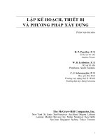
</div><span class="text_page_counter">Trang 7</span><div class="page_container" data-page="7">3 Figure 1. Structural Plan of Building
</div><span class="text_page_counter">Trang 8</span><div class="page_container" data-page="8">4 Figure 2. Structural cross-section A-A
</div><span class="text_page_counter">Trang 9</span><div class="page_container" data-page="9">5 Figure 3. Structural cross-section B-B
</div><span class="text_page_counter">Trang 10</span><div class="page_container" data-page="10">6
<b>3. Foundation structure </b>
- Depth of foundation:
H = 3t = 120 + m*10 = 120 + 1*10 = 130 (cm) <small>m</small> → choose t = 45 (cm) - Foundation sizes:
+ Middle footing:
a =<sup>1</sup><sub>10</sub>× 𝐿<small>max</small>+ 10 × 𝑇 =<sup>1</sup><sub>10</sub>×700 + 10 6 = 130 (cm) ×b = 0.7𝑎<small>𝑚𝑔</small>= 0.7 × 130 91= <sub> (cm) </sub><sub>→</sub><sub> choose b 95 (cm) </sub><sub>= </sub>
<b>4. Ground </b>
- Reinforced concrete : 10+ 2𝑚 =10+ 2 × 1 =12 (cm) - Lining concrete: (cm) 10
</div><span class="text_page_counter">Trang 11</span><div class="page_container" data-page="11">7 - Foundation sand: 90 12 10 68− − = (cm)
<b>5. Roof </b>
- Waterproofing:
4.5 +<sup>𝑛</sup><sub>20</sub>= 4.5 +<sup>1</sup><sub>20</sub>= 4.55(cm) choose 5 (cm) →- Heat proofing :
12 +<sup>𝑛</sup><sub>3</sub>= 12 +<sup>1</sup><sub>3</sub>=<sup>37</sup><sub>3</sub>≈ 12.33 ( ) choose 13 (cm) cm →- 2 layers of traditional terra-cotta floor tiles (ceramic tile)
</div><span class="text_page_counter">Trang 12</span><div class="page_container" data-page="12">8
<b>6. Wall </b>
- Along the axis of the building Exterior wall 220 (mm), interior wall 110 (mm). : - Plaster 40% area of exterior wall, 50% area of interior wall.
- Paint 40% area of exterior wall: 50% of interior wall area.
- Doors (and windows) take 60% area of exterior wall, 10% area of interior wall.
<b>7. Power, water factor </b>
- 0,32 working hour per 1m area of floor. <small>2</small>
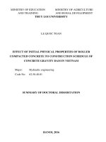
<i>Figure 4. Construction site </i>
Figure 5. Building location on construction site
</div><span class="text_page_counter">Trang 13</span><div class="page_container" data-page="13">- Backfilling the first time (at the height of foundation surface ).- Installing column formwork.
- Pouring column concrete. - Dismantling column formwork. - Backfilling the second time. - Embankment.
- All foundations in this project have the same dimensions. - The figure below shows the dimensions of a typical foundation. - Select the dimensions of foundation beam: 25x40(cm).
<b>Conclusion: From the calculated data above => Excavation method: Using mechanical and </b>
manual method.
The excavation plan is one pit for whole building foundation. Foundation pit is excavated from ground level (-0.9m) to the position which is 100mm far from the bottom level of foundation (-2.25m) by mechanical method and then adjusting by manual method.
</div><span class="text_page_counter">Trang 14</span><div class="page_container" data-page="14">- Dismantling column formworks, installing formwork of beams and slabs. - Installing reinforcement of beams, slabs.
- Pouring beam and slab concrete. - Dismantling beam and slab formworks.
Zone <sup>Structural </sup><sub>Element </sub> <sup>Concrete Volume </sup><sub>per Element (m ) </sub><small>3</small> Element count (unit)
</div><span class="text_page_counter">Trang 15</span><div class="page_container" data-page="15">Reinf. Ratio ( ) ( )
Unit weight of
steel (kG/m<small>3</small>)
Reinforcement per zone (kG/m<small>3</small>)
</div><span class="text_page_counter">Trang 16</span><div class="page_container" data-page="16">Formwork area per Element
(m2)
Element count (unit)
Formwork area per zone (m2)
Total formwork area (m2)
</div><span class="text_page_counter">Trang 18</span><div class="page_container" data-page="18">33 − Firstly, identify the column center and the limitation of height for concrete pouring
(painting the column steels…).
− Adjust the standby steels of the column and install the column structure.
− Pouring high strength concrete as the column base at the column-foot mark with its section-dimensions like that of column and 3-5 cm height.
− The formwork boards at the column sides are nailed to make a box with 3 sides (1 side has large width and 2 sides has smaller width). Afterward, the box is installed in the column location and installed with formwork boards of the remain sides of the column. − Adjust the accuracy of the center of the column formwork and ensure the vertical position of the column formwork. Use the brace, foot-props to fix the column formwork. • Removal:
− Follow the principle: First installed, second removed first removed, second installed. –− Make sure to avoid the formwork is sticked to the column formwork that causing
damages on concrete surface during removal.
o Continue by installing the beam edge’s formwork (after installing the beam’s reinforcement): after laying the beam edge’s formwork to its location, adjust the located formwork and use the flying post/prop, brace/struts and foot-hold bar to fix the formwork boards. The edge boards have to perpendicular to the bottom’s boards.
o Adjust the height and location and bind the props together.
− Install the joints for slab and post/props. Adjust the height and location by the geodesic machine and wedges. Installation of slab joints: First, joints are temporarily laid on 2 ledgers to determine the height for joint. Afterward, install the posts/props for the joints (use the wedge).
− Spread the slab boards/sheeting and edge sheeting.
</div><span class="text_page_counter">Trang 19</span><div class="page_container" data-page="19">34 − Adjust the height of slab formwork to comply with the design by using wedges at the
foot of the slab joints posts/props. • Removal:
− The dismantlement sequence is reversed to the installation sequence.
− First, lower slab posts/props and beam by moving the wedges. Afterward, strip the sheeting out the concrete slab. Incline the slab boards to remove it from the posts/props. Because the edge sheeting is covered by concrete, we need to use the crowbar to break the concrete. Similar techniques used for the beam bottom’s board.
Imported steel will be fabricated to make reinforcement steels of reinforced concrete structures. The steps of fabricating are straightening, measuring, cutting and bending based on design. These steps may be executed by hands or machines. Technical requirements for fabrication and installation are illustrated below.
<b>a) Straightening: </b>
− For steel roll (Φ≤10mm), we use capstan (whether electrical capstan of hand-controlled capstan) for straightening. It is requested to have a flat floor of 30-50m length. Steel roll will be placed on a support with rotating axle to avoid twisting for the steel bar.
− For steel roll with diameter Φ>10mm (11.7mm long and fold in two), use worker’s force to adjust the bar to be relatively straight, then use hammer to complete the straightening.
<b>b) Rust scraping: </b>
− Reinforcement steel before fabricating, installation or pouring concrete must be scraped rust. − Iron brushes or steel-whittling tools may b used in rust scraping. e
<b>c) Measuring, Cutting and Bending </b>
− Before cutting or bending, steel bar must be measured and marked for the fabricating to be accurate. The marker is by white chalk or paint.
− Steel bar before bending must be studied in term of the allowable extension while bending. o Bending angle 45<small>𝑜</small>, the extension is 0.5d (d: diameter of steel bar ).
o Bending angle 90<small>𝑜</small>, the extension is 1d. o Bending angle 180<small>𝑜</small>, the extension is 1.5d.
− When the cutting is mass executed, we can make a spacer, or take one bar as the standard for the cutting the other bars. The standard bar should be used from beginning to end to avoid the accumulated tolerances.
− May use bending machine and bar bender for bending.
<b>d) Splicing: </b>
Reinforced concrete structures are designed to behave monolithically. Properly designed splices of individual reinforcing bars are a key element in transmitting forces through the structure and
</div><span class="text_page_counter">Trang 20</span><div class="page_container" data-page="20">35 creating a load path. The architect/engineer provides location, lap length, and related information on structural drawings.
− No joining at the positions where major loading and bending exist.
− On each section, the joining should not be over 25% of the numbers of steel bars with smooth/ undeformed bars and should not be over 50% of the numbers of steel bars with deformed bars. − The lap length (L) of the reinforcement steel in frames and wire fabric is not shorter than 250mm for steel in tension area, not shorter than 200mm for steel in compression area, and not shorter than the figures shown below (d: diameter of the reinforcement steel).
<b>a) Technical requirements for concrete </b>
The principles governing proper placement of concrete are detailed in TCVN 4453-1995, but not limited to some notes as following:
− Segregation must be avoided during all operations between the mixer and the point of placement, including final consolidation and finishing.
− The concrete must be thoroughly consolidated, worked solidly around all embedded items, and should fill all angles and corners of the forms.
− Where fresh concrete is placed against or on hardened concrete, a good bond must be developed.
− Unconfined concrete must not be placed under water.
− The temperature of fresh concrete must be controlled from the time of mixing through final placement and protected after placement.
<b>b) General procedure for placement </b>
Currently, ready-mix concrete is often preferred on site. Ready mix concrete is a concrete which is manufactured as per required mix ratio in batching plant, and then is transported to construction site on truck mixers. As being produced under factor conditions, this type of concrete guarantees the highest possible quality. Material storage and mixing conditions are unavoidably far from ideal. Even if uniform high quality is maintained at the mixer, it is recently lost during subsequent handling before it reaches the formwork.
• Placement method:
The placement methods of ready mixal ed concrete play an important role as it affects the strength and durability of concrete structures. The time of delivery, quality checks and time of placements affects the ready mixal ed concrete. In normal condition, concrete should be placed within 4 hours since it is mixed at the batching plant. Concrete may be conveyed from a mixer to point of placement by any of a variety of method and equipment, if properly transported to avoid segregation. The most appropriate technique for placing concrete depends on jobsite conditions,
</div><span class="text_page_counter">Trang 21</span><div class="page_container" data-page="21">36 especially project size, equipment, and the contractor’s experience. In building construction, concrete usually is placed with hand-or power operated buggies, drop bottom buckets with a –crane, inclined chutes, flexible and rigid pipe by pumping, and for underwater placing, tremie chutes (closed flexible tubes).
• Consolidation:
The purpose of consolidation is to eliminate voids of entrapped air and to ensure intimate complete contact of the concrete with the surfaces of the forms and the reinforcement. Intense vibration, however, may also reduce the volume of desirable entrained air, but this reduction can be compensated by adjustment of the mix proportions. Powered internal vibrators are usually used to achieve consolidation. For thin slabs, however, high-quality, low-slump concrete can be effectively consolidated, without excess water, by mechanical surface vibrators. If concrete is not consolidated well, defects will appear after removing formwork.
Some precautions necessary to avoid ill effects are:
(1) Place concrete in level layers through closely spaced trunks or chutes. (2) Do not place concrete full depth at each placing point.
(3) Do not move concrete laterally with vibrators.
(4) On any delay between placing of layers, vibrate the concrete thoroughly at the interface. (5) If concreting must be suspended between planned horizontal construction joints, level off the layer cast, remove any laitance and excess water, and make a straight, level construction joint, if possible, with a small clear attached to the form on the exposed face.
(6) The depth of each concrete layer should not exceed 3/4 times the vibrator head length. Time for each consolidation is from 15 to 60 second, until the concrete is not slumped anymore, and cement paste shows on the surface.
• Inspection of concrete placement:
Concrete should be inspected before, during, and after casting. Before concrete is placed, it is required to inspect the formwork, rebars, and concrete’s performance. The formwork must be free of dust and debris and properly coated with bond-breaker oil. The reinforcing bars must be in place, properly supported to bear any traffic they will receive during concrete placing. Conduit, insects, and other items to be embedded must be position, fixed against displacement. As concrete cast, the slump of the concrete must be observed and regulated within prescribed limits to ensure specified strength.
There should be at least one inspector of placing who is also responsible for sampling and making cylinders, should test slump, entrained air, temperatures, and unit weights. Any field adjustment of slump and added water and cement must be controlled. The inspector should also ascertain that the approved construction procedure is properly followed.
</div><span class="text_page_counter">Trang 22</span><div class="page_container" data-page="22">37 Inspection is complete only when concrete is cast, finished, protected for curing, and attains full strength.
<b>4. Construction method for main tasks </b>
Plywood formwork with is selected for this problem because: - The surface of concrete is even and good looking. - Quick process, simple to install or remove. - Less of buckling or crack.
- High reusable ability.
Reinforcement is installed partly. Each part of reinforcement is built up in the ground and then they
<b>are installed into the formwork. By this method: </b>
- The quality of reinforcement is controlled better. - Ensuring the position of steel bars as designed. - About splice of reinforcing steel:
- Tying method is easy to build but cannot bear the huge load, so it is ideally for horizontal structures as beams and slabs.
The amount of crack and shrinkage could be reduced.
<b>5. Selection of construction machines </b>
Using crane that used in substructure for superstructure construction. • Crane parameter
+ Hoisting level: <i>H<small>select</small></i>= 25.00m+ Working range: <i>R<small>select</small></i>= 70m+ Load capacity: <i>Q<small>select</small></i>= 2.66T - 10T+ Cycle of tower crane: 𝑇<small>𝑐𝑘</small>= ∑<sup>𝑛</sup><small>𝑖=1</small>𝑡<small>𝑖</small>= 462 42s. • Required height of tower crane.
H<small>required </small>= H + H + H + H<small>bssck</small>Where:
</div><span class="text_page_counter">Trang 23</span><div class="page_container" data-page="23"><i>+ H<small>sc</small>- height of structural components, h<small>sc</small></i>= 1.5m
→ H<small>required</small>= 20.3 + 1 + 1.5 + 1.5 = 24.3m • Working range of tower crane:
𝑅<small>𝑟𝑒𝑞𝑢𝑖𝑟𝑒𝑑</small>= √(<sup>𝐿</sup><sub>2</sub><sup>+ 𝐵</sup><small>𝑠𝑐</small>)<small>2</small>
+ (𝐵 + 2𝐵<small>𝑠𝑐</small>+ +𝑆 𝐷)<small>2</small>Where:
• Load capacity
𝑄<small>𝑟𝑒𝑞𝑢𝑖𝑟𝑒𝑑</small>= 𝑉<small>𝑏</small>× 𝛾<small>𝑐𝑜𝑛𝑐𝑟𝑒𝑡𝑒</small>+ 𝑀 Where:
<i>+ M </i>- self-weight of concrete bucket, <i>M </i>= 260kg = 0.26T → 𝑄<small>𝑟𝑒𝑞𝑢𝑖𝑟𝑒𝑑</small>= 1.5× 2. + 04 .26 = .86 (T) 3
• Productivity of crane (for concrete transporting only): o Productivity of tower crane per working hour:
𝑁 = 𝑄.3600
𝑇<small>𝑐𝑘</small> . 𝑘<small>1</small>(𝑚<small>3</small>/ℎ𝑜𝑢𝑟) 𝑁 = 1.5 ×3600
451.4× 0,9 = 10.8 (𝑚<small>3</small>/ℎ𝑜𝑢𝑟)
</div>