đồ án thiết kế hệ thống cơ khí thiết bị tự động đề tài thiết kế hệ thống phân loại sản phẩm
Bạn đang xem bản rút gọn của tài liệu. Xem và tải ngay bản đầy đủ của tài liệu tại đây (2.51 MB, 50 trang )
<span class="text_page_counter">Trang 1</span><div class="page_container" data-page="1">
<b><small>ĐẠI HỌC BÁCH KHOA HÀ NỘI</small></b>
<b><small>Sinh viên thực hiện: Nguyễn Duy Tùng Anh - 20195759Giảng viên hướng dẫn: Trịnh Đồng Tính</small></b>
<small>Hà Nội, tháng 4 năm 2023</small>
</div><span class="text_page_counter">Trang 2</span><div class="page_container" data-page="2"><small>TRƯỜNG ĐẠI HỌC BÁCH KHOA HÀ NỘISME.EDU –Mẫu 6.a</small>
<b><small> ĐỒ ÁN MÔN HỌC: THIẾT KẾ HỆ THỐNG CƠ KHÍ Mã HP: ME3066</small></b>
<small> Thời gian thực hiện: 15 tuần; Mã đề: VCK01-19Ngày giao nhiệm vụ: 10/04/2023; Ngày hoàn thành://2023Họ và tên sv:</small> Nguyễn Duy Tùng Anh <small> MSSV: </small>20195759 <small>Mã lớp:729127 </small>
<b><small>I.Nhiệm vụ thiết kế: Thiết kế hệ thống phân loại sản phẩmII. Số liệu cho trước:</small></b>
<small>1. Hệ thống cấp phôi tự động</small>
<small>2. Nguồn lực cấp phơi và đẩy phơi: Khí nén3. Nguồn lực quay băng tải: Động cơ điện4. Bộ truyền ngồi: Xích</small>
<small>5. Thơng số hình học phơi: </small>
<small></small><i><b><small> Hình lập phương : h1= 3cm, h2= 4cm, h3= 5cm</small></b></i>
<i><small>6. Trọng lượng phôi: Qmin = 0.5 kg; Qmax</small></i><small> = 6.5 kg</small>
<i><small>7. Năng suất làm việc : N = 20 sp/ph</small></i>
<b><small>III. Nội dung thực hiện:</small></b>
<b><small>1. Phân tích ngun lý và thơng số kỹ thuật</small></b>
<small>- Tổng quan về hệ thống- Nguyên lý hoạt động</small>
<small>- Phân tích tính chất, đặc điểm của phơi/sản phẩm để lựa chọn phương pháp cấp phôi phù hợp- Xác định các thành phần cơ bản và thông số/yêu cầu kỹ thuật của hệ thống </small>
<b><small>2. Tính tốn và thiết kế</small></b>
<small>- Thiết kế các mô đun chức năng của hệ thống:</small>
</div><span class="text_page_counter">Trang 3</span><div class="page_container" data-page="3"><small>+ Mô đun cấp phôi tự động+ Mơ đun băng tải</small>
<small>+ Mơ đun phân loại: pít tơng khí nén, van từ, sensor, ...</small>
<b><small>3. Thiết kế chi tiết và xây dựng bản vẽ lắp</small></b>
<small>- Xây dựng bản vẽ lắp 2D/3D</small>
<small>- Xây dựng các bản vẽ chế tạo các chi tiết chính</small>
<b><small>4. Mơ phỏng ngun lý hoạt động (động học)</small></b>
<small>Đề số</small> <sup>Năng suất</sup><small>làm việc</small> <sup>Trọng lượng phơi</sup> <sup>Kích thước hình học phơi (cm)</sup>
</div><span class="text_page_counter">Trang 4</span><div class="page_container" data-page="4">Today, due to the constant development of technology, the need of a fast and convenient application in industries is necessary. Automation is a practical solution which helps increase the speed, accuracy and reduce labor price.
In the era of industrialization and modernization of Vietnam, the automatic control of production and product processing has been increased. This results in the forming of flexible production systems, allowing a high degree of automation for small and medium batch production on the basis of CNC machines and industrial robots. Automation is also utilized in the product category system, which is an important stage affecting the quality of commercial goods.
<i><b>The project " Designing an automatic product classification system " was</b></i>
conducted in order to reinforce students' knowledge and at the same time help them recognize the connection between the theoretical knowledge and the practical applications and use. The topic has many important applications in fields such as product transportation, counting and classification. With this automation system labor and production cost can be reduced.
Given the broad range of general knowledge, there are multiple areas of knowledge that I have not mastered despite having consulted technical documents.
<i><b>Hence, when implementing the project " DESIGN OF MECHANICAL</b></i>
<i><b>ELECTRICAL SYSTEMS ", it is unavoidable that limitations and shortcomings</b></i>
exist. We look forward to receiving constructive advice and the support of lecturers and peers.
<i><b>We sincerely thank the lecturers in the Department of Technology mechanical</b></i>
<b>and especially …, who has enthusiastically guided, created favorable conditions</b>
and given us valuable knowledge for the completion of this subject project.
<b>Thank you sincerely </b>
</div><span class="text_page_counter">Trang 5</span><div class="page_container" data-page="5"><b>TABLE OF CONTENTS</b>
<b>FIGURE LIST...6</b>
<b>CHAPTER 1:...7</b>
<b>OVERVIEW OF THE PRODUCT CLASSIFICATION SYSTEM...7</b>
<b>1.1 Definition and Application...7</b>
<b>3.1.1. Calculate the parameters of the conveyor geometric and kinetics. 193.1.2. Calculate the tensile force...21</b>
<b>3.1.3 Choose the roller (Active/Passive)...23</b>
<b>3.1.4 Test strength of the belt...27</b>
<b>3.1.5 Choose the motor...27</b>
<b>3.1.6. Choose the external transmission...30</b>
<b>3.2 Choose automatic work-piece feeding system...35</b>
<b>3.3 Pneumatic system and cylinder calculation...36</b>
<b>3.3.1 Introduction of compressed air system and components...36</b>
<b>3.3.2 Calculate the piston...38</b>
<b>3.3.3 Calculate the air compressor...39</b>
<b>3.4 Choose sensor...41</b>
</div><span class="text_page_counter">Trang 6</span><div class="page_container" data-page="6"><b>CHAPTER 4:...43</b>
<b>DESIGNING SYSTEM MODEL ON SOFTWARE...43</b>
<b>4.1 Overview of SOLIDWORKS software...43</b>
<b>4.2 Basic components of the system...44</b>
</div><span class="text_page_counter">Trang 7</span><div class="page_container" data-page="7"><b>FIGURE LIST</b>
<small>Figure 2.1 Conveyor model in real life...8</small>
<small>Figure 2.2 Belt conveyor...9</small>
<small>Figure 2.3 Chute conveyor...10</small>
<small>Figure 2.4 Gravity conveyor...10</small>
<small>Figure 2.5 Powered roller conveyor...11</small>
<small>Figure 2.6 Bucket conveyor...11</small>
<small>Figure 2.7 Ball transfer conveyor...12</small>
<small>Figure 2.8 Slat conveyor...12</small>
<small>Figure 2.9 Train conveyor...13</small>
<small>Figure 2.10 Trolley conveyor...13</small>
<small>Figure 2.11 Structure of the piston...15</small>
<small>Figure 2.12 How sensor works...16</small>
<small>Figure 2.13 Types of motor...16</small>
<small>Figure 3.1 Length of conveyor, distance between products...19</small>
<small>Figure 3.2 Forces acting on conveyor...22</small>
<small>Figure 3.3 Active roller...23</small>
<small>Figure 3.4 Forces acting on roller...24</small>
<small>Figure 3.5 Moment chart Oy...25</small>
<small>Figure 3.6 Moment chart Ox...26</small>
<small>Figure 3.7 TAILI-MINHMOTOR Speed control motor...29</small>
<small>Figure 3.8 Forces acting on piston...38</small>
<small>Figure 3.9 DSNU piston catalog...39</small>
<small>Figure 3.10 Piston’s journey...39</small>
<small>Figure 3.11 Air compressor Wing TW-OF750-25l -1HP...40</small>
<small>Figure 3.12 Infrared sensor E18-D80NK...41</small>
<small>Figure 4.1 Main frame...44</small>
<small>Figure 4.2 Conveyor belt...45</small>
<small>Figure 4.3 Feeder...45</small>
<small>Figure 4.4 Roller...46</small>
<small>Figure 4.5 Chain transmission...46</small>
<small>Figure 4.6 Large Sprocket...47</small>
<small>Figure 4.7 Small Sprocket...47</small>
<small>Figure 4.8 Model...48</small>
</div><span class="text_page_counter">Trang 8</span><div class="page_container" data-page="8"><b>CHAPTER 1:</b>
<b>OVERVIEW OF THE PRODUCT CLASSIFICATION SYSTEM1.1 Definition and Application</b>
A product classification system is an automatic or semi-automatic control system which categories products with similar feature for packaging or discarding flawed products.
These types of systems include for example:
<small>Based on the control method: automatic or semi-automatic systems, without orwith human participation to a certain extent, controlled by PLC and microprocessor.</small>
<small>By color: the color sensor will recognize the color and convert it to electricalsignal and then through an ADC converter to the processor.</small>
<small>According to the weight, shape and size.</small>
<b>1.2 Working principle</b>
Based on sensors to classify types of products (cylinder and cube, its height)
Basic technical requirements of functional clusters in the system:
+ Conveyor speed is sufficient to achieve working productivity and engine with enough capacity for stable operation of the transmission system.
+ The system of pushing work pieces with compressed air has low latency to avoid affecting the product classification sensor.
</div><span class="text_page_counter">Trang 9</span><div class="page_container" data-page="9"><b>CHAPTER 2:</b>
<b>BASIC COMPONENTS OF THE SYSTEM2.1 Conveyor</b>
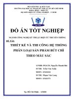
<i><small>Figure 2.1 Conveyor model in real life</small></i>
The main characteristics of conveyors for purposes of classification are the type of traction and the load-carrying elements. A distinction is made between conveyors with belt, chain, and cable drive elements and conveyors without a drive element (gravitational, inertial, and screw conveyors). Conveyors with drive elements can be differentiated by type of load-carrying elements into belt, apron, cradle, flight, and bucket types. Such conveyors are characterized by movement of the load together with the working element. The thrust is transmitted either by the load-carrying element or by an element that pushes or pulls the material along a fixed trough, tube, or bed. In conveyors without a drive element the movement of the load is usually separate from the movement of the working elements, which revolve in roller and screw conveyors or perform reciprocating motion in, for example, inertial conveyors. Conveyors may have a machine drive (most often electric; sometimes pneumatic), or the load may be moved by the force of gravity (gravitational conveyors).
</div><span class="text_page_counter">Trang 10</span><div class="page_container" data-page="10"><b>Advantages of conveyor belt:</b>
- Simple structure, durable, capable of transporting separately and individually in horizontal, inclined or a combination of horizontal and inclined.
- The investment capital is not very large, can be automated, simple operation, easy maintenance, reliable work, high productivity and energy consumption compared to other transport machines is not very large.
Types of conveyor belts on the market today
When designing a conveyor system to transport products to a sorting location, you can choose from the following types of conveyors:
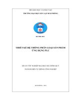
<i><b>2.1 Belt Conveyor</b></i>
<i><small>Figure 2.2 Belt conveyor</small></i>
This is probably what you picture when you think of a conveyor. They are simple devices—a moving belt turned by pulleys—but are very useful. A motor is used to turn the pulleys, thus moving the belt.
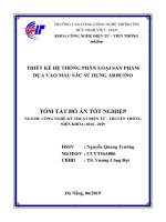
<b>Chute Conveyor</b>
</div><span class="text_page_counter">Trang 11</span><div class="page_container" data-page="11"><b> Figure 2.3 Chute conveyor</b>
Picture a slide for your packages. Chute conveyors are metal slides used to transport packages down to a lower level of your warehouse. They are cheap but using them can increase the odds of packages bumping into each other and getting damaged.
<b>Gravity Roller Conveyor</b>
<i><small>Figure 2.4 Gravity roller conveyor</small></i>
Instead of a belt, this device uses cylindrical rollers. It is built at a slight decline so parts slide downward on their own.
</div><span class="text_page_counter">Trang 12</span><div class="page_container" data-page="12"><b>Powered Roller Conveyor</b>
<i><small>Figure 2.5 Powered roller conveyor</small></i>
This is like a gravity roller conveyor except a chain or belt is used to make the rollers turn on their own, so they don’t have to be built on a decline. Sometimes they can even go uphill.
<b>Bucket Conveyor</b>
<i><small>Figure 2.6 Bucket conveyor</small></i>
Grain elevators, which we discussed here, fall under this category. Bucket
</div><span class="text_page_counter">Trang 13</span><div class="page_container" data-page="13">conveyor systems are used to move material vertically, by scooping it with a series of buckets attached to a belt, chain, or cable. The conveyor moves the buckets upward, scooping up the material, and carrying it to the top before dumping it out.
<b>Ball Transfer Conveyor</b>
<i><small>Figure 2.7 Ball transfer conveyor</small></i>
This type of conveyor system is described as: “Ball Transfer tables or conveyors use a series of mounted ball casters to allow for unpowered, multi-directional conveyance of the product.” Essentially, imagine rows of metal balls on a table that can turn and rotate in any direction. This allows material to be pushed in different directions (as opposed to rollers which can only go forwards and back).
<b>Slat Conveyor</b>
<i><small>Figure 2.8 Slat conveyor</small></i>
“A slat conveyor is basically a two-strand chain conveyor with slats connected
</div><span class="text_page_counter">Trang 14</span><div class="page_container" data-page="14">to the chain and a guiding system for the slats. This creates a smooth surface to which tooling details or fixtures can be mounted to hold parts in the desired position.”
</div><span class="text_page_counter">Trang 15</span><div class="page_container" data-page="15"><b>Chain Conveyor</b>
<i><small>Figure 2.9 Chain conveyor</small></i>
These are exactly what they sound like. Instead of having rollers or a belt, they have moving chains to carry products. They are usually low to the ground and are used to carry larger items.
<b>Trolley Conveyor</b>
<i><small>Figure 2.10 Trolley conveyor</small></i>
There is a whole family of conveyors that carry their load beneath them instead of on top of them. Sometimes the load is hung from an overhead beam and pushed along. Other times they are motorized. Sometimes, as with the Power- and-Free
</div><span class="text_page_counter">Trang 16</span><div class="page_container" data-page="16">Conveyor, they have two tracks—one motorized and one not motorized.
<i>Because the conveyor is used in the system to transport products, in this project I have chosen a belt conveyor for the following reasons:</i>
<i>- Conveyor load is not too large.</i>
<i>- The mechanical structure is not too complicated.- Easy to design and manufacture.</i>
However, this type of conveyor also has some disadvantages such as: the accuracy when transporting is not high, sometimes the conveyor belts operate unstable due to many factors: environmental temperature affects rollers, friction of the belt drops through.
<b>2.2 Piston</b>
<b>A piston is a component of reciprocating engines, reciprocating pumps, gas</b>
compressors, hydraulic cylinders and pneumatic cylinders, among other similar mechanisms. It is the moving component that is contained by a cylinder and is made gas-tight by piston rings. In an engine, its purpose is to transfer force from expanding gas in the cylinder to the crank shaft via a piston rod and/or connecting rod. In a pump, the function is reversed and force is transferred from the crankshaft to the piston for the purpose of compressing or ejecting the fluid in the cylinder. In some engines, the piston also acts as a valve by covering and uncovering ports in the cylinder.
The piston is usually cylindrical, divided into 3 parts including the pavilion, head and body:
- In the piston nails, there are 3 types of convex, concave and equal. Each piston peak receives high temperature gas pressure. The piston head section has oil ring grooves and cement rings when used for mounting in the device. The grape holes at the top of the oil capacity are opened into the bottom of the trench to perform the task of supplying and escaping. The number of ring slots depends on the engine type. On the piston body, there are horizontal holes, performing the task of guiding the piston to move in the cylinder to transmit the force to rotate the crankshaft when linked with the transmission rod to perform the function of mounting the piston connecting pin and the transmission rod. The body of a diesel engine's piston is usually longer than the piston body of a gasoline engine and the base usually has an additional 1-2 rings of oil ring. In order to facilitate the air conditioning when working from the carburetor to the engine crankcase, the piston
</div><span class="text_page_counter">Trang 17</span><div class="page_container" data-page="17">body of the two-stroke engine does not have a gas cylinder with a bottom hole or a defect.
<b>Working principle of the piston:</b>
- The piston base is compressed at a certain temperature and pressure, the piston operates automatically through the compressed air supply. Thanks to the difference between the pressure at the outside school and the pressure level in the piston act to supply the piston. The source of compressed air is the energy that helps the piston work. Pistons can go all the way, requiring gas in the piston to be discharged. When there is a type of pneumatic electronic valve in the piston that causes the air to expand, the compressed air is converted into kinetic energy. In the piston cavity, air will be compressed when supplying gas to the piston. Energy is generated and transformation is performed. This amount of gas generates work that helps the device work while taking up the space inside the piston, causing the piston to move. Therefore, depending on the performance of the device, the piston operates in a variety of methods to regulate intermediate stops. At the same time control the amount of expansion or retraction of the piston rod
<i><small>Figure 2.11 Structure of a piston</small></i>
<b>2.3 Sensor</b>
<b><small>In general, sensor is known as a Detector. A sensor is an electronic equipment that is</small></b>
<small>used to detect and observe the physical activities and pass the notification/signal to otherelectrical control devices. In other words, a sensor is an electronic device that cantransform energy from one form to another form. So, it is also called a</small>
<b><small>Transducer. The main function of the sensor is to identify and communicate with</small></b>
<small>physical quantities such as temperature, heat, pressure, distance, moisture, gas, and so</small>
</div><span class="text_page_counter">Trang 18</span><div class="page_container" data-page="18"><small>on. And it provides output in the form of electrical signal to connected control systems.</small>
<i><small>Figure 2.12 How sensor works</small></i>
<small>According to the principle of the sensor there are:- Electronic and ion sensors</small>
<small>According to the nature of the power source:- Generator sensor</small>
<small>- Parameter sensor</small>
<small>According to the measuring method:- Direct variable sensor- Compensation sensor</small>
<b>2.4 Motor </b>
<i><small>Figure 2.13 Motor</small></i>
<b><small>2.5.1 Definition</small></b>
<small>Electric motors in general and DC motors in particular are rotating electromagneticdevices, working according to the electromagnetic principle, when placed in a magneticfield by a conductor and allowing current to flow through the conductor to make the coilmove. An electric motor converts electrical energy into mechanical energy.</small>
<b><small>2.5.2 Working Principle</small></b>
<small>The stator of a DC motor is usually one or more pairs of permanent magnets, orelectromagnets, the rotor has windings and is connected to a DC power source, anotherimportant part of a DC motor is rectifier, it is responsible for changing the direction ofcurrent while the rotation of the rotor is continuous. Usually this part consists of a</small>
</div><span class="text_page_counter">Trang 19</span><div class="page_container" data-page="19"><small>commutator and a set of brushes in contact with the commutator.</small>
If the shaft of a DC motor is pulled by an external force, the motor will act as a DC generator, and generate an induced Electromotive force (EMF). During normal operation, the rotor when rotating will generate a voltage called counter-EMF (Ccounter-EMF), because it opposes the external voltage applied to the motor. This electromotive force is similar to that generated when the motor is used as a generator (like when we connect a load resistor to the motor output, and pull the motor shaft by an external torque). Thus, the voltage applied to the motor consists of two components: the electromotive force, and the voltage drop caused by the internal resistance of the armature windings.
</div><span class="text_page_counter">Trang 20</span><div class="page_container" data-page="20"><b>CHAPTER 3: CALCULATION AND DESIGN OF THESYSTEM COMPONENT</b>
<b>*Overview of transmission system:</b>
With: 1. Motor, 2. Clutch, 3. Gearbox, 4. Chain drive, 5. Conveyor
Electric motors usually have high rotation speed. So the rotation from the motor will be reduced through the gearbox, then reduced again through the chain drive and transmit to the conveyor in order to reach optimal working speed.
<i>For my project, I choose motor with built in gear box, focus on designing the chaindrive system and the conveyor</i>
</div><span class="text_page_counter">Trang 21</span><div class="page_container" data-page="21"><b>3.1 Conveyor system</b>
- Input parameters
+ Geometrical parameters of products:
Cubes: h<small>1</small>=3 (cm) h<small>2</small>=4 (cm) h<small>3</small>=5 (cm) + Weight of block: Q<small>min</small> = 0.5kg Q<small>max</small> = 6.5 kg + Working capacity: N = 20 block/min
+ Source of power: Electrical motor
<i><small>Figure 3.1 Length of conveyor, distance between products</small></i>
<i><b>3.1.1 Calculate the parameters of the conveyor geometric and kinetics</b></i>
<b>- Find L:</b>
• L = d + (n-1). Y
Where: n is the number of product on the conveyer at 1 time (n=4) d is the diameter of products (d=0.05m)
Y is the distance between the center of 2 products (choose Y=0.3m)
=> L = 0.05 + (4 - 1).0.3 = 0.95(m) <b>Choose L=1.3m</b>
</div><span class="text_page_counter">Trang 22</span><div class="page_container" data-page="22"><b>- Find W:</b>
<b>-</b> <i><sup>Y</sup><sub>v</sub></i>
>
<i><sup>2(M+W )</sup><sub>v</sub></i>With: Y is the distance between the center 2 products (choose Y=0.3m) v is the speed of the conveyor
<i><sup>v</sup></i><small>1</small> is the speed of the pistons (choose FESTO brand)
M is the distance from product’s edge to the conveyor’s edge
</div><span class="text_page_counter">Trang 23</span><div class="page_container" data-page="23">Choose DSNU-20-200, <i><sup>v</sup></i><small>1</small>=0.5(m/s) at Q<small>max</small> = 6.5 kg
<b>Frame structure: Shaped aluminum</b>
I choose PVC conveyor belt because of these advantages:Wear and scratch resistant, Broad range in types, Easy the rework, Price friendly, Easy to clean, Oil and grease resistant
<i><b>3.1.2 Calculate tensile force</b></i>
<b>- Analysis forces applied on the conveyor belt</b>
Primary tensile force:
+ Friction force between surface of belt and roller made by weight of blocks and belt
+Initial belt tension
</div><span class="text_page_counter">Trang 24</span><div class="page_container" data-page="24">Tension at point S1 => S4:<i><sup>S</sup><small>i</small></i><b> = </b><i><sup>S</sup><small>i−1</small></i><b> + </b><i><sup>W</sup><small>i−1 /i</small></i>
With: <i><sup>W</sup><small>i−1 /i</small></i><b> is the drag force from point (i-1) to point (i).</b>
</div><span class="text_page_counter">Trang 25</span><div class="page_container" data-page="25">-Band drag force is the force transmitted from the guide drum to the belt
<b>F = </b><i><sup>S</sup></i><small>3</small><b> – </b><i><sup>S</sup></i><small>0</small><b> = Σ</b><i><sup>W</sup><small>i−1 /i</small></i><b> = 2.86 + 0.06</b><i><sup>S</sup></i><small>0</small><b> + 0.172 + 89.55 = 0.06</b><i><sup>S</sup></i><small>0</small><b> + 92.58 (N)</b>
So to determine the drag force F we need to know the value of S0. The force S0 can be determined from the condition of sufficient frictional force to transmit force at the path:
S<small>3</small> ≤ S<small>0</small>.e<small>fα</small>
F = S<small>3</small> - S<small>0</small> ≤ S<small>0</small>.(e<small>fα</small> - 1)
With: α: angle of embrace of the tape on tang , α =<i><small>π</small></i>
f: coefficient of friction between the tape and the tang (0.2 ~ 0.4).
</div>