graduation project research and experiment of eco mode device apply to ice vehicle innova model
Bạn đang xem bản rút gọn của tài liệu. Xem và tải ngay bản đầy đủ của tài liệu tại đây (3.31 MB, 123 trang )
<span class="text_page_counter">Trang 1</span><div class="page_container" data-page="1">
<b>HO CHI MINH CITY UNIVERSITY OF TECHNOLOGY AND EDUCATION FACULTY FOR HIGH QUALITY TRAINING</b>
<b>GRADUATION PROJECT</b>
<b>RESEARCH AND EXPERIMENT OF ECO MODEDEVICE APPLY TO ICE VEHICLE (INNOVA MODEL)</b>
<b>Student ID: 18145029</b>
<b>Student ID: 18145007</b>
<b>Major: AUTOMOTIVE ENGINEERING Advisor: DUONG TUAN TUNG, Ph.D.</b>
Ho Chi Minh City, August 2021
</div><span class="text_page_counter">Trang 2</span><div class="page_container" data-page="2"><b>HO CHI MINH CITY UNIVERSITY OF TECHNOLOGY AND EDUCATIONFACULTY FOR HIGH QUALITY TRAINING</b>
<b>GRADUATION PROJECT</b>
<b>RESEARCH AND EXPERIMENT OF ECO MODEDEVICE APPLY TO ICE VEHICLE (INNOVA MODEL)</b>
<b>Student ID: 18145029</b>
<b>Student ID: 18145007</b>
<b>Major: AUTOMOTIVE ENGINEERING Advisor: DUONG TUAN TUNG, Ph.D.</b>
</div><span class="text_page_counter">Trang 3</span><div class="page_container" data-page="3">Ho Chi Minh City, August 2021 THE SOCIALIST REPUBLIC OF VIETNAM
<b>Independence – Freedom– Happiness</b>
Ho Chi Minh City, August 1, 2022
<b>GRADUATION PROJECT ASSIGNMENT</b>
Date of assignment: Date of submission:
1. Project title: “Research and Experiment of ECO mode device apply to ICE vehicle (Innova model)”
2. Initial materials provided by the advisor:
Innova 2009 vehicle & 1NZ-FE service manual & Textbook 3. Content of the project:
Papers related to ECO mode device for Innova vehicle model, tools, software, experiments with the device and measure equipments.
4. Final product: Thesis report including the caculation, simulation and experimental results.
<b>CHAIR OF THE PROGRAMADVISOR</b>
</div><span class="text_page_counter">Trang 4</span><div class="page_container" data-page="4"><b>Independence – Freedom– Happiness</b>
Ho Chi Minh City, August 1, 2022
<b>ADVISOR’S EVALUATION SHEET</b>
Major: Automotive Engineering.
Project title: “Research and Experiment of ECO mode device apply to ICE vehicle (Innova 6. Mark………. (in words:...)
Ho Chi Minh City, August 14, 2022.
<b>ADVISOR</b>
</div><span class="text_page_counter">Trang 5</span><div class="page_container" data-page="5"><b>Independence – Freedom– Happiness</b>
Ho Chi Minh City, August 1, 2022
<b>PRE-DEFENSE EVALUATION SHEET</b>
Major: Automotive Engineering.
Project title: “Research and Experiment of ECO mode device apply to ICE vehicle (Innova model)” 6. Mark………. (in words:...)
Ho Chi Minh City, August 1, 2022.
<b>REVIEWER</b>
</div><span class="text_page_counter">Trang 6</span><div class="page_container" data-page="6"><b>Independence – Freedom– Happiness</b>
Ho Chi Minh City, August 1, 2022
<b>EVALUATION SHEET OF DEFENSE COMMITTEE MEMBER</b>
Major: Automotive Engineering.
Project title: Research and experiment of ECO Mode device on ICE apply to ICE vehicle (Innova 5. Mark………. (in words:...)
Ho Chi Minh City, August 1, 2022
</div><span class="text_page_counter">Trang 8</span><div class="page_container" data-page="8">We hereby declare that this is our own research project, the thesis is done at Ho Chi Minh City University of Technology and Education under the guidance of PhD. Duong Tuan Tung. The data and results presented in the thesis are completely honest and not has been published by anyone in any other work. I also hereby declare that all references for the implementation of the thesis has been explicitly cited.
</div><span class="text_page_counter">Trang 9</span><div class="page_container" data-page="9">To complete the graduate project on time and achieve the results only the effort of the person who made the topic, but also the assistance and advice of the Faculty of Vehicle and Energy Engineering and Faculty of High-Quality Training and the motivation and experience of classmates, the project team completed the graduation project on time.
Our group would like to sincerely thank to:
- The guidance and enthusiastic help of Mr. Duong Tuan Tung for instructing, providing necessary documents and supporting to check and correct inaccurate information.
- Our team would like to thank the Ho Chi Minh City University of Technology and Education lecturers, Faculty of Vehicle and Energy Engineering, and Faculty of High-Quality Training for their dedication to instruction, imparting experience and knowledge in the learning and training process so that we could have today success. In the process of implementing this project, although we have tried our best, there will be inevitable shortcomings. We hope to receive the comments and criticism of lecturers and students.
Once again, thank you lecturers and students!
Ho Chi Minh City, August 2022 Group member
Nguyen Dang Khoi – Nguyen Thanh Danh
</div><span class="text_page_counter">Trang 10</span><div class="page_container" data-page="10"><b>1.Purpose of thesis selection: ... 1 </b>
<b>2.Research object and scope: ... 2 </b>
<b>3.Research content ... 3 </b>
<b>4.Research method ... 3 </b>
<b>5.Scientific significance of the research thesis: ... 3 </b>
<b>6.Structure of the thesis: ... 3 </b>
<b>Chapter 1 : INTRODUCTION ... 5 </b>
<b>1.1.Problem statement. ... 5 </b>
<b>1.2.Review of related studies. ... 6 </b>
<b>1.2.1.Factors affecting fuel use – Auxiliary system ... 7 </b>
<b>1.2.2.Engine control methods of manufactures. ... 8 </b>
<b>1.2.3.Research on driving modes. ... 16 </b>
<b>1.3.Research ECO mode – fuel saving mode. ... 18 </b>
<b>1.3.1.What is ECO mode? ... 18 </b>
<b>1.3.2.What does ECO mode do? ... 18 </b>
<b>1.3.3.Other names for ECO mode. ... 19 </b>
<b>1.3.4.When should ECO mode be used? ... 20 </b>
<b>1.3.5.Some disadvantages of ECO mode. ... 20 </b>
</div><span class="text_page_counter">Trang 11</span><div class="page_container" data-page="11"><b>1.3.6.Conclusion. ... 21 </b>
<b>Chapter2: LITERATURE REVIEW ... 22 </b>
<b>2.1.Theory of electronic throttle control: ... 22 </b>
<b>2.1.1.Basic build: ... 22 </b>
<b>2.1.2.Electronic throttle control algorithm ... 23 </b>
<b>2.1.3.Optimization of the electronic throttle control process: ... 28 </b>
<b>2.2.Research on the second generation Toyota Innova. ... 29 </b>
<b>2.2.1.Research the popularity of car models on the market. ... 29 </b>
<b>2.2.2.Engine control system ... 31 </b>
<b>2.2.3.Introduction to the 1NZ-FE engine and control system ... 32 </b>
<b>Chapter 3: BUILDING MODEL, DESIGN AND MANUFACTURING EQUIPMENT. ... 42 </b>
<b>3.1.Research on driving mode control device ... 42 </b>
<b>3.1.1.Methods of changing vehicle power. ... 42 </b>
<b>3.1.2.Tweak the ECU ... 42 </b>
<b>3.1.3.Research and manufacture ECO driving mode controller ... 45 </b>
<b>3.2.Simulate the structure of the device on Proteus software. ... 47 </b>
<b>3.3.Simulate media on Matlab Simscape ... 50 </b>
<b>4.1.1.ECO BOX device. ... 68 </b>
<b>4.1.2.Fuel consumption meter model 9531A. ... 70 </b>
<b>4.1.3.Techstream Program ... 72 </b>
<b>4.2.Experiment procedure. ... 75 </b>
</div><span class="text_page_counter">Trang 12</span><div class="page_container" data-page="12"><b>4.2.1.Installation for first-time run. ... 75 </b>
<b>4.2.2.Idle test. ... 75 </b>
<b>4.2.3.Road test. ... 76 </b>
<b>4.3.Experimental test drive and driving cycle data: ... 78 </b>
<b>CONCLUSION AND RECOMMENDATIONS ... 87 </b>
<b>1.Conclusion: ... 87 </b>
<b>2.Recommendations. ... 87 </b>
<b>REFERENCES ... 88 </b>
</div><span class="text_page_counter">Trang 13</span><div class="page_container" data-page="13"><b>List of figures</b>
Figure 1. 1. Some mechanisms that align the accelerator pedal position with the sensor are
highlighted in red...6
Figure 1. 2. Basic car comfort system...7
Figure 1. 3. Mini cooper 2008 – the first BMW model equipped with the Start-stop system. 8 Figure 1. 4. Hondad 3 phases VTEC...11
Figure 1. 5. BMW Vanos system...12
Figure 1. 6. Toyota VVTL-I system...14
Figure 1. 7. Rover's VVC system...15
Figure 1. 8. Some comparision on different drive modes acceleration proccess...17
Figure 2. 1. Structure of an electronic throttle control system...22
Figure 2. 2. Block diagram of throttle control system...24
Figure 2. 3. Throttle parameter values...27
Figure 2. 4. The relationship between Torque and air mass...28
<b>Figure 2. 5. External image of the engine and RPM-P-T graph...Error! Bookmark notdefined.</b> Figure 2. 6. Location of details on the 1NZ-FE engine...35
Figure 3. 1. Example of the process of building a program to fine tune ECU...43
Figure 3. 2. A JB4 brand multifunctional Piggyback set...44
Figure 3. 3. Independent ECU Speeduino and Arduino open source application...44
Figure 3. 4. Schematic diagram of the motor speed control system...45
Figure 3. 5. Device operating location. ... 46
Figure 3. 6. Simulation estimates the relationship between accelerator pedal position and voltage level... 46
Figure 3. 7. LM741... 47
Figure 3. 8. Simulate ECO mode control device...48
Figure 3. 9. Signal control structure ... 49
Figure 3. 10. Throttle control signal W/WO ECO BOX...50
Figure 3. 11. Matlab Simscape...51
Figure 3. 12. S-PS converter unit...51
Figure 3. 13. PS-Simulink converter... 52
</div><span class="text_page_counter">Trang 14</span><div class="page_container" data-page="14">Figure 3. 14. Engine block...52
Figure 3. 15. Mechanical Rotational Reference...54
Figure 3. 16. Torque Converter...54
Figure 3. 17. Vehicle Body... 55
Figure 3. 18. Block diagram of the simulation. ... 56
Figure 3. 19. 2021 Generation Toyota Innova...57
Figure 3. 20. Driving Cycle signal...59
Figure 3. 21. Vehicle simulation model (General)...60
Figure 3. 22. Simscape Results... 61
Figure 3. 23. Block diagram of Model’s operation...62
Figure 3. 24.Vehicle speed graph (m/s)...63
Figure 3. 25. Power graph... 64
Figure 3. 26. Fuel consumption graph...65
Figure 3. 27. Engine speed graph...66
Figure 3. 28. Torque graph... 67
Figure 4. 1. ECO BOX device... 68
Figure 4. 2. Installation of ECO BOX...69
Figure 4. 3. FC Meter 9531A...70
Figure 4. 4. Main components of FC- 9531A...71
Figure 4. 5. Installation position of FC sensor...72
Figure 4. 6. Interface of Toyota Techstream program...72
Figure 4. 7. VCI cable to connect the laptop with Techstream program to OBD2 port...73
Figure 4. 8. Flow diagram of Installation for first-time run...75
Figure 4. 9. Flow diagram of Idle test...75
Figure 4. 10. Flow diagram of Road test. ... 76
Figure 4. 11. Driving cycle map ... 78
Figure 4. 12. Normal mode driving cycle data ... 79
Figure 4. 13. ECO mode driving cycle data ... 80
Figure 4. 14. Sport mode driving cycle data ... 81
Figure 4. 15 Injection volume Normal mode ... 82
Figure 4. 16 Injection volume Eco mode ... 82
Figure 4. 17 Injection volume Sport mode ... 83
Figure 4. 18 Engine speed Normal mode ... 83
Figure 4. 19 Engine speed Eco mode ... 84
</div><span class="text_page_counter">Trang 15</span><div class="page_container" data-page="15">Figure 4. 20 Engine speed Sport mode ... 84
Figure 4. 21 Vehicle speed Normal Mode ... 85
Figure 4. 22 Vehicle speed Eco mode ... 85
Figure 4. 23 Vehicle speed Sport mode ... 86
</div><span class="text_page_counter">Trang 16</span><div class="page_container" data-page="16"><b>List of table</b>
driving cycle data.
</div><span class="text_page_counter">Trang 17</span><div class="page_container" data-page="17">In recent years, the automobile market in Vietnam has made great progress in many aspects such as production , sales , service, etc. . . Thanks to the government's supportive policies in many directions, the automobile industry in Vietnam has gradually become saturated with other countries in Asia. The number of cars per capita in Vietnam is also gradually increasing year by year. But most of those new cars are located in the low-end and popular segments, the reason for that is the rapid development of the online passenger transportation system - typically Grab and service cars (Taxi). The characteristics of these cars are moderate prices, easy to use but it lacks advanced comfort functions. Meanwhile, users' demand for driving experience in multiple modes is increasing. In addition, the driving modes Sport, Racing or ECO are rarely equipped on these models.
Therefore, in order to improve the above disadvantages, the author decided to research and manufacture a device to select the driving mode applied for GRAB and TOYOTA INNOVA vehicles. And one of the main objectives of the research direction is to evaluate the efficiency of the vehicle when installing the mode selector with the vehicle without the mode selector in order to study the feasibility and economics of the device. In this thesis, the author will give an overview of engine control through modes, present the theoretical basis of electronic throttle control, use Matlab/ Simulink Simscape software to build the device and actual testing of the device. From those results will give an overview of the effectiveness
<b>of the device on the vehicle's operation compared to other traditional vehicles.</b>
</div><span class="text_page_counter">Trang 18</span><div class="page_container" data-page="18"><b>11. Purpose of thesis selection:</b>
Today, the problem of environmental pollution is a problem that is mentioned a lot in global conferences. And in the IEA report [1] on the world's CO<small>2 </small>emissions, in 2020 the
industrial production. and transportation. In recent years, along with the socio-economic development, the number of private means of transport in our country has also increased rapidly. According to the Vietnam registry as of July 2021, there are more than 14 million motorbikes and 4.2 million cars of all kinds. In which, vehicles using internal combustion engines account for 90% of the total number of existing vehicles. With a large number of vehicles, the amount of fuel used every year is also large and at the same time it also creates a large amount of CO<small>2 </small>emissions to the environment.
Thanks to the development of technology and techniques, the structure of the automobile is more modern and comfortable, most of which are equipped with intelligent systems to bring safety, stability, fuel economy and other safety features. car customer experience. The typical fuel-saving system research methods can include the fuel-saving modes of companies such as Toyota, Ford, Honda . . . The start-stop system on BMW, the variable valve control system and the system GDI direct injection . . . and including the ECO intelligent driving mode control system with the ability to create driving modes suitable to the movement conditions of the car to be effective in terms of torque and power and also control the fuel consumption of the vehicle. According to designs from car manufacturers around the world, fuel-saving driving mode can reduce fuel consumption by up to 5%, which shows great economic benefits from this feature. But in reality today, the control system for intelligent driving modes ECO has not been much equipped in most of the low-segment cars of Taxi companies.
Although there have been many studies published such as research on factors affecting fuel consumption and CO2 emissions of passenger cars [2], the study of Fontarnas [3] ablout the fuel consumption in Europe, research on reducing emissions in passenger transport [4] to contribute to improving environmental pollution and maximizing the benefits
</div><span class="text_page_counter">Trang 19</span><div class="page_container" data-page="19">of natural resources. However, if put into practice, the research can only affect the hardware and the fuel
</div><span class="text_page_counter">Trang 20</span><div class="page_container" data-page="20">optimization systems are not always available on every car model. Finding effective ways to increase fuel economy and optimize system control on existing vehicles becomes extremely necessary.
Therefore, if conducting research and installing this system on Toyota Innova lines, it will be able to contribute to improving vehicle performance, user's driving experience, reducing fuel consumption, thereby reducing fuel consumption. reduce costs for both users and taxi service providers and contribute to environmental protection. On that basis, the author chose to research and manufacture a device to select the driving mode application for Toyota Innova. The study was conducted to study the electronic throttle control system, contributing to reducing fuel consumption and improving the user's experience when driving. To realize the above goals. This is a device that is directly attached to the accelerator pedal and ECU, through the ECU controlling the input signal from the accelerator pedal to control the desired output signal on the electronic throttle set.
<b>2. Research object and scope:Research subjects:</b>
The object of the research is the ECO mode control device for the 2nd generation Toyota model (from 2007 to 2014, 1NZ-FE engine). The device will be installed directly on the vehicle. The research was carried out at the chassis and bodywork research room, Ho Chi Minh City University of Technology and Education.
Matlab software Simulink Simscape will be used to model the motor control system. Studying blocks serves the purpose of studying the engine and operation of the blocks mentioned above.
<b>Research scope:</b>
Learn about ECO modes on vehicles from various manufacturers. Learn about ways to save fuel with minimal hardware impact. Develop a plan to design and control a set of fuel-saving devices, control vehicles according to pre-set running modes. Studying the effect of the device on the technical and economic performance and emission of the engine. Research methods to determine fuel consumption without using
</div><span class="text_page_counter">Trang 21</span><div class="page_container" data-page="21">specialized equipment. Research, develop and upgrade the ECO fuel-saving mode controller.
</div><span class="text_page_counter">Trang 22</span><div class="page_container" data-page="22"><b>3. Research content:</b>
<b>- Research and simulate the</b> Innova engine and build the engine model on Matlab Simscape <small>® ® </small><b>.</b>
<b>- Research and design equipment on Proteus simulation environment.- Research on 1NZ-FE motor speed control method.</b>
<b>- Experimenting with operability and evaluating the efficiency of the control device to </b>
evaluate the engine's ability to optimize fuel use and emissions.
<b>- Research and build RPM/Torque/ fuel ratio diagram.4. Research method:</b>
The thesis uses theoretical research methods, modeling combined with experimental research to evaluate the operability, efficiency and scientificity of the research result. In addition, to build the knowledge base on thesis in a scientific and effective way, the method of document review is also applied.
<b>5. Scientific significance of the research thesis:</b>
This is the first scientific study built on the device. Currently on the market, there are devices that help increase power through increasing the amount of air entering the combustion chamber, these devices can increase engine power in a short time but damage the engine and increase fuel consumption is very significant. Therefore, the device is not intended to increase capacity. Instead, if successfully researched, the device can be used to create more fuel-saving modes that are easy to use for vehicles that do not have the ECO system available or the ECO system does not have high efficiency. Help save fuel, increase engine life and can also improve efficiency.
Researching methods to optimize engine power through throttle controller optimization.
Proposing to widely apply and commercialize the ECO mode control device.
<b>6. Structure of the thesis:</b>
The structure of the thesis is divided into the following sections:
</div><span class="text_page_counter">Trang 23</span><div class="page_container" data-page="23">• Preamble.
• Main Content section. Consists of: - Chapter 1: Overview
- Chapter 2: Theoretical basic;
- Chapter 3: Building model, design and manufacturing equipment; - Chapter 4: Experiment with Eco box device.
• Conclusion and recommendation.
</div><span class="text_page_counter">Trang 24</span><div class="page_container" data-page="24"><b>1.1. Problem statement.</b>
<b>Chapter 1 : INTRODUCTION</b>
Much of the process of controlling a vehicle is controlling its speed. The vehicle's speed comes from the engine's traction and is routed through the transmissions to the rotating mechanism of the wheels. On each gasoline car, the driver will use the accelerator pedal to control the amount of fuel entering the engine and the throttle system will control the amount of air entering to create a mixture of air and air into the cylinder. Accordingly, accelerator pedal control also allows the driver to control engine torque to accelerate the vehicle and maintain the desired speed, as well as reduce or eliminate torque to slow down and stop the vehicle. Previously, the throttle was controlled directly by the driver via the accelerator pedal based on a mechanical connection (e.g. Bowden cable) and if the vehicle was equipped with an automatic throttle then another cable was added. connected to the throttle valve and the cruise control actuator. One way or another, the throttle position must be determined to control the proper amount of fuel injection.
In 1988, the first electronic throttle control (ETC) system was introduced [5], which eliminated the mechanical connection between the accelerator pedal and the throttle body by replacing it with an electronic control system. complete. This system includes the pedal sensor, throttle sensor and actuator as well as the necessary control unit. ETC is a technology that allows advanced features including cruise control and vehicle stability control to be made easier and is widely used in cars today. Since the operation of the ETC system is related to the safety of the driver, the quality control requirements on the accelerator pedal sensor are relatively strict [6].
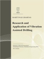
</div><span class="text_page_counter">Trang 25</span><div class="page_container" data-page="25">Figure 1. 1. Some mechanisms that align the accelerator pedal position with the sensor are highlighted in red.
The general trend of car manufacturers today is towards driving comfort, increasing driving feeling, increasing safety for the whole system. Those requirements are expressed through technical features such as: high linearity, low latency, small deviation and equivalent sensitivity with long life. Along with the development of other industries, the automobile manufacturing industry has undergone many periods of replacing and renewing the method of controlling engine speed with different types of sensors.
<b>1.2. Review of related studies.</b>
In this section, the author presents researches on fuel-saving methods and applications to improve internal combustion engines of some car manufacturers such as BMW, TOYOTA, HONDA on Variable Valve Timing, Smart Cam in high-end car models and research on driving modes in car manufacturers. Besides, there is an overview study of two driving modes, ECO.
</div><span class="text_page_counter">Trang 26</span><div class="page_container" data-page="26"><b>1.2.1. Factors affecting fuel use – Auxiliary system.</b>
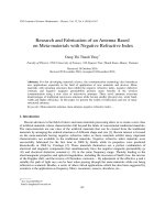
Auxiliary systems refer to elements and accessories that improve driving safety and comfort such as air cleaning systems, lighting systems [7], wipers, doors power windows, heating and air conditioning systems [8], parking assist, collision warning [9]. These devices are not normally operated continuously, however this work did not consider the usage factors in detail due to lack of information. Auxiliary use requires an increased electrical or mechanical supply, thereby increasing the power demand of the engine and fuel consumption. The latter rates are estimated in order of 9% for the use of the air conditioning, up to 4.5% for the steering assist system and up to 6.5% for the other ancillary items. According to the literature, optimization and advanced technologies can provide fuel consumption benefits of up to 2%. Purely mechanical auxiliary systems are losing their place compared to electrical systems serving the same purpose.
Figure 1. 2. Basic car comfort system.
A variety of energy needs for additional electrical and mechanical loads have been evaluated by simulation. This resulted in an average increase of 14.9% for NEDC (New European Driving Cycle) and 9.6% for WLTP (Worldwide Harmonised Light Vehicle Test Procedure). for global light vehicles), are considered relatively high values for the intended
</div>