subject project design an scada for mixer system
Bạn đang xem bản rút gọn của tài liệu. Xem và tải ngay bản đầy đủ của tài liệu tại đây (7.19 MB, 38 trang )
<span class="text_page_counter">Trang 1</span><div class="page_container" data-page="1">
HO CHI MINH UNIVERSITY OF TECHNOLOGY AND EDUCATION
<b>FACULTY OF HIGH QUALITY TRAINING</b>
<b>SUBJECT PROJECT</b>
<b>Design An Scada for Mixer System</b>
<b>Student: Quản Quốc Tân – 16142636 Course: 2016</b>
<b>Major: Electrical – Eletronic Engineering Instructors : Ngô Văn Thuyên</b>
<b>Ho Chi Minh City, January 2019</b>
</div><span class="text_page_counter">Trang 3</span><div class="page_container" data-page="3">4.2. System Configuration Selection...3
4.2.1. Centralized I/O With PC...3
4.2.2. Distributed I/O...5
4.2.3. Distributed Or Independent Data Collection And Control Units...6
4.2.4. Programming Tools For IEEE-488...8
5. Component Selection...8
5.1. SIMATIC CPU S7 – 300 315-2 PN/DP (6ES7 315-2EH14-0AB0)...8
5.2. HMI Touch Panel...10
5.3. Water Level Sensor – Optomax Digital Range of Liquid Level Switches12 5.4. Rosemount TankRadar PRO (Radar Level Gauge)...13
</div><span class="text_page_counter">Trang 4</span><div class="page_container" data-page="4">1. PLC Program...25
1.1. Main (OB1)...25
1.2. Main Program Block (FC2)...25
1.3. Storage Tank Block (FC3)...26
1.4. Alarms Block (FC1)...27
2. PLC Tags... 29
</div><span class="text_page_counter">Trang 5</span><div class="page_container" data-page="5"><b>LIST OF ABBREVIATIONS</b>
SCADA Supervisory Control And Data Acquisition HMI Human Machine Interface
0
</div><span class="text_page_counter">Trang 6</span><div class="page_container" data-page="6"><b>LIST OF FIGURES</b>
<b>Figure 4.1: PCI Card PD2-AO-16/16...3</b>
<b>Figure 4.2: Centralized I/O diagram...4</b>
<b>Figure 4.3: Block diagram of Power DAQ - AO - 16/16 and -32/16 boards...4</b>
<b>Figure 4.4: Block diagram...5</b>
<b>Figure 4. 5: Using PCMCIA card to collect the data from stand-alone...6</b>
<b>Figure 4.6: Stand-alone data collector via RS-232 serial communication...6</b>
<b>Figure 4.7: Connect the Stand-alone data collector via the telephone network or radio7Figure 4.8: Distributed data collection system...7</b>
<b>Figure 4.9: Structure of one commonly GPIB system...8</b>
<b>---Figure 5.1: CPU S7-300 315-12 PN/DP 6ES7 315-2EH14-0AB0...10</b>
<b>Figure 5.2: The SIMATIC HMI TP900...11</b>
<b>Figure 5.3: Optomax Digital Water Level Sensor...13</b>
<b>Figure 5.4: Beam angle of TankRadar sensor...14</b>
<b>Figure 5.5: Electrical Connections...14</b>
<b>Figure 5.6: The main specification of TankRadar sensor...15</b>
<b>Figure 5.7: The measurement range of TankRadar sensor...15</b>
<b>---Figure 6.1: The state diagram of program...16</b>
<b>---Figure 7.1: HMI display design...17</b>
<b>Figure 7.2: The Symboic I/O field...18</b>
<b>Figure 7.3: The set value for 5000 liters...19</b>
<b>Figure 7.4: The higher value of MW30 are set...19</b>
<b>Figure 7.5: The cyan indicator will light on after two pumps ran 3 times...20</b>
<b>Figure 7.6: Yellow indicator flashing...20</b>
<b>Figure 7.7: Red indicator flashing...21</b>
<b>---Figure 8.1: At the begin of the system...21</b>
0
</div><span class="text_page_counter">Trang 7</span><div class="page_container" data-page="7"><b>Figure 8.2: After press START/STOP and ON/OFF buttons...22</b>
<b>Figure 8.3: Low level sensor detected...22</b>
<b>Figure 8.4: High level sensor detected, mixer run in 10 second...23</b>
<b>Figure 8.5: Valve open, flow sensor detect the liquid and activate storage pump...23</b>
</div><span class="text_page_counter">Trang 8</span><div class="page_container" data-page="8"><b>Design an Scada for Mixing System</b>
<b>1.Overview</b>In industrial process engineering, mixing is a unit operation that involves manipulation of a heterogeneous physical system with the intent to make it more homogeneous. Familiar examples include pumping of the water in a swimming pool to homogenize the water temperature, and the stirring of pancake batter to eliminate lumps (deagglomeration). Mixing is performed to allow heat and/or mass transfer to occur between one or more streams, components or phases.
Modern industrial processing almost always involves some form of mixing. Some classes of chemical reactors are also mixers. With the right equipment, it is possible to mix a solid, liquid or gas into another solid, liquid or gas. A biofuel fermenter may require the mixing of microbes, gases and liquid medium for optimal yield; organic nitration requires concentrated (liquid) nitric and sulfuric acids to be mixed with a hydrophobic organic phase; production of pharmaceutical tablets requires blending of solid powders. The opposite of mixing is segregation.
The type of operation and equipment used during mixing depends on the state of materials being mixed (liquid, semi-solid, or solid) and the miscibility of the materials being processed. In this context, the act of mixing may be synonymous with stirring-, or kneading-processes. In this project, the substances which are mixed is the liquid – liquid.
Mixing of liquids occurs frequently in process engineering. The nature of liquids to blend determines the equipment used. Single-phase blending tends to involve low-shear, high-flow mixers to cause liquid engulfment, while multi-phase mixing generally requires the use of high-shear, low-flow mixers to create droplets of one liquid in laminar, turbulent or transitional flow regimes, depending on the Reynolds number of the flow. Turbulent or transitional mixing is frequently conducted with turbines or impellers; laminar mixing is conducted with helical ribbon or anchor mixers. Mixing of liquids that are miscible or at least soluble in each other occurs frequently in process engineering (and in everyday life). An everyday example would be the addition of milk or cream to tea or coffee. Since both liquids are water-based, they dissolve easily in one another. The momentum of the liquid being added is sometimes enough to cause enough turbulence to mix the two, since the viscosity of both liquids is relatively low. If necessary, a spoon or paddle could be used to complete the mixing process. Blending in a more viscous liquid, such as honey, requires more mixing power per unit volume to achieve the same homogeneity in the same amount of time.
</div><span class="text_page_counter">Trang 9</span><div class="page_container" data-page="9"><b>2.Project Objective and Scopes</b>
The objective of this mini project is design an scada system and design an HMI touch panel for mixing system. With scada system, the user can follow and observe whole system parameters. For control those parameters, system need an HMI screen to adjust that value. The information of the system also be shown on the screen include the work flow of the system.
This mini project just limit in the mixing field, at the basic of the mixer system. By that, the acknowledge for mixing system in particularly and the scada system in general will be more clearly and easy to be acquired. Beside that, HMI touch panel (HMI screen) also been created. The HMI can help supervise and acquire the control data. These HMI screen can be replace by the computer desktop with bigger screen.
<b>3.Design Requirements</b>
For this mixing system, the system can work properly. In addition, the system have to detect these following trouble and show on the screen what is going on with the system as following:
- The system run automatically
- When 2 pumps of mixer tank ran after 3 times, light 3 will be on. A reset button will reset the light.
- Can set the liquid level of storage tank, when the level at 5000 liters, blink the yellow light, at 8000 liters blink the red light.
- The mixer run in 10 second, after 10 second, the valve open to drain out the substance in the mixer tank.
- The supervisory and acquisition data control can be adjust through the HMI.
<b>4.System Operation and System Configuration Selection4.1. System Operation</b>
At initial, the system will not run until the START/STOP button pressed. After the whole system run, ON/OFF will be pressed to enable two digital level sensors in the mixer tank while the tank radar sensor (analog sensor) measure the level of the liquid in the storage tank. We set the high limit level. the level of the liquid in the storage tank will show on the HMI screen. If the level is over the limit, the system will alarm to the operator. While the tank radar sensor do its work, two digital level sensors in the mixer tank will detect the level of the liquid inside. If the liquid at the low level, two pumps will be enabled and pump the substance to the mixer tank until the substance hit the high level sensor, two pumps stop and mixing process will be start. The mixer will run in 10 second, after 10 second, the mixer stop and valve will be
</div><span class="text_page_counter">Trang 10</span><div class="page_container" data-page="10">opended. The liquid after mixing will be transferred into the storage tank. When the substance in the mixer tank drain out and hit the low level sensor, two pumps will continue its cycle. Until two pumps run 3 times (this times can be change depend on the request of the customer), light 3 on the HMI screen will be light on. There is a reset button to do the job reset that light.
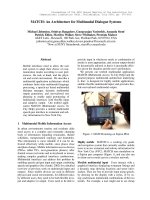
<b>4.2. System Configuration Selection4.2.1. Centralized I/O With PC</b>
Centralized I/O circuits are plugged directly into the computer via extended buses. The feature of this type are: small, highest speed of collect signal and control, low so beacause its commonly used. This system are commonly used in the PC application which are nearby the sensor and the executive structure. The system block
<b>diagram is shown in the Figure 4.2.</b>
About PCI Card PD2 – AO – 16/16:
- This is PCI Card have 16 channel, 16 bit with 100kS/s speed for each analog out channel
- Use for PCI slot
- 16 analog out channel with 16bit resolution - 8 digital input, 8 digital output
- 3 interrupt input/clock, 3 timer/counter 24bit - Independent waveforms in each channel
- Simultaneous update of channel, function update according to the external event
- 2k caching memory onboard (upgrade to 64k samples)
</div><span class="text_page_counter">Trang 11</span><div class="page_container" data-page="11"><b>Figure 4.1: PCI Card PD2-AO-16/16</b>
<b>Figure 4.2: Centralized I/O diagram</b>
</div><span class="text_page_counter">Trang 12</span><div class="page_container" data-page="12"><b>Figure 4.3: Block diagram of Power DAQ - AO - 16/16 and -32/16 boards4.2.2. Distributed I/O</b>
Sensors and actuators are commonly far from PCs. In industrial environments,sensors and actuators are in harsh environments and cover hundreds of meters away from PCs.
In the noise enviroments, its hard to receive the small signal from the sensor as thermocouple, strain gauge through the long transmition.
The rope connect from sensor to PC is long and maybe expensive. So there is a solution for this type: the distrubuted I/O mean that the signal conditioning modules are placed nearby each sensor corresponding. For each sensor, they need one signal conditioning module. With this solution can be costly if there are multiple sensors but its can be offset by signal and precision.
The common form of distributed I / O is a digital transmitter. This digital transmitter performs all the necessary signal conditioning functions, with VXL and ADC to convert the signal to be measured into digital form. This digital signal is transmitted to PC by RS-232 or RS-485 standard.
RS-232 (point to point): bulky when there are have many point
RS-485 (multi-drop): reduce the transmission cable, can connect up to 32 modules, transmission distance can be up to 10km if use multi-drop network. (RS-232 maximum is 15m)
Usually we need an adapter to convert RS-232 to RS-485 because almost PC did not support the RS-485 standards.
</div><span class="text_page_counter">Trang 13</span><div class="page_container" data-page="13"><b>Figure 4.4: Block diagram</b>
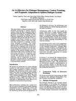
<b>4.2.3. Distributed Or Independent Data Collection And Control Units</b>
The advantages of this type is likely the advantages of Distributed I/O with smart signal conditioning, beside that the ability to make remote decisions for itself increases system reliability.
Can control and setup configuration from PC using series communication or PCMCIA card. It can work independently without PC (this is the main object of this type), so that its very useful when place the DAQ far away or in harsh enviroment or application do not allow the continuos connect to the PC. For example is temperature control in refrigenerated truck.
</div><span class="text_page_counter">Trang 14</span><div class="page_container" data-page="14"><b>Figure 4. 5: Using PCMCIA card to collect the data from stand-alone</b>
<b>Figure 4.6: Stand-alone data collector via RS-232 serial communication</b>
</div><span class="text_page_counter">Trang 15</span><div class="page_container" data-page="15"><b>Figure 4.7: Connect the Stand-alone data collector via the telephone network or radio</b>
<b>Figure 4.8: Distributed data collection system</b>
</div><span class="text_page_counter">Trang 16</span><div class="page_container" data-page="16"><b>4.2.4. Programming Tools For IEEE-488</b>
This communication standards is called GPIB (General Purpose Interface Bus), its was founded by Hewlett-Packard to connect and control the measure equipment test programming. This standards fastly accepted by the world and become a IEEE-488 standards by speed, flexibility and useful in the connection of equipment in lab together.
GPIB is a communication standards high speed parralel allow connect simultaneous 15 devices on data transmission parralel bus.
Usually request having a GIPB to locate the adress for each devices. The maximum communication speed, the maximum transmission cable length and the maximum distance between devices depend on the speed and ability of GPIB processing and the cable transmission type.
This type suitable for research lab or test measure in industry. There are a thousand product on the market support this type (IEEE-488).
<b>Figure 4.9: Structure of one commonly GPIB system</b>
Because of the sensors and acutuals are far away from the PCs so the suitable configuration for this system is <b>Distributed I/O</b>. With analog sensor, the tank radar sensor is a sensor with transducer integrated inside. The transmitter module will be placed nearby the sensors and actuals.
<b>5.Component Selection</b>
<b>5.1. SIMATIC CPU S7 – 300 315-2 PN/DP (6ES7 315-2EH14-0AB0)</b>
Siemens AG is a German multinational conglomerate company headquartered in Munich and the largest industrial manufacturing company in Europe with branch
</div><span class="text_page_counter">Trang 17</span><div class="page_container" data-page="17">offices abroad. Siemens offers a wide range of electrical engineering- and electronics-related products and services. Its products can be broadly divided into the following categories: buildings-related products; drives, automation and industrial plant-related products; energy-related products; lighting; medical products; and transportation and logistics-related products. Siemens drives, automation and industrial plant-related products include motors and drives for conveyor belts; pumps and compressors; heavy duty motors and drives for rolling steel mills; compressors for oil and gas pipelines; mechanical components including gears for wind turbines and cement mills; automation equipment and systems and controls for production machinery and machine tools; and industrial plant for water processing and raw material processing. Siemens also create the SIMATIC CPU such as S7-300 is a famous one in the series SIMATIC STEP 7 CPU.
The SIMATIC STEP 7 series is at the middle to high end of the S7 range of<small>[3]</small>
PLCs, it is the most commonly used controller across most industries for general automation. There was a cheaper option in the form of an S7-200 (shoebox PLC) but this line is now discontinued and has been replaced by the far superior S7-1200. The main differences between an S7-300 and an S7-200 are:
- Cost the cost is generally higher for modules and equipment for the rack than it is for S7-200 but at the mid to low end of the range it is significantly cheaper than the S7-400
- The speed, 0.075ms - 0.018ms /1000 instructions-- Built in memory (RAM), 32kB – 2.56MB - Connections (Direct) 6 – 64
- Addressing memory 1kB - 8kB - Additional modules to the CPU 8 – 32
It is a modular series but not standard DIN mountable like the S7-200 or 1200 range, there is a special rail to be bought and fitted to your backplane to mount the S7-300 racks. S7-S7-300 takes more space than a shoebox PLC series such as the S7-200 but much less than a rack mounted series such as S7-400. It is available in many different configurations to your choosing with additional modules available for:
- Digital I/O in multiple sizes from 8-64
- Analogue I/O sizes from 2-8 with hart communication - Industrial Ethernet communications cards
- Profibus communications cards - ASI communications cards - RS-232 communications cards
</div><span class="text_page_counter">Trang 18</span><div class="page_container" data-page="18">- RS-422 communications cards - RS-485 communications cards
The system can be expanded to 4 racks in total with 1 master and 3 expansion racks. Each rack is completely to your choosing up to a maximum of 8 usable modules per rack. The main rack contains 10 with your CPU and expansion module taking up the other 2 slots and each expansion has 9 with the first slot being taken by the receiving expansion module (this is to a maximum of 32). All of this needs to be set up during the Hardware Configuration and must be downloaded to the PLC before downloading any blocks that use any address you may be adding otherwise when called this will put the CPU in stop.
The S7-300 CPUs come in a wide range of performance options with four
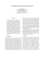
</div><span class="text_page_counter">Trang 19</span><div class="page_container" data-page="19"><b>5.2.HMI Touch Panel</b>
A touchscreen, or touch screen, is a both input and output device and normally layered on the top of an electronic visual display of an information processing system. A user can give input or control the information processing system through simple or multi-touch gestures by touching the screen with a special stylus or one or more fingers. Some touchscreens use ordinary or specially coated gloves to work while others may only work using a special stylus or pen. The user can use the touchscreen to react to what is displayed and, if the software allows, to control how it is displayed; for example, zooming to increase the text size.
The user interface or human–machine interface (HMI) is the part of the machine that handles the human–machine interaction. Membrane switches, rubber keypads and touchscreens are examples of the physical part of the Human Machine Interface which we can see and touch.
In complex systems, the human–machine interface is typically computerized. The term human–computer interface refers to this kind of system. In the context of computing, the term typically extends as well to the software dedicated to control the physical elements used for human-computer interaction.
The engineering of the human–machine interfaces is enhanced by considering ergonomics (human factors). The corresponding disciplines are human factors engineering (HFE) and usability engineering (UE), which is part of systems engineering.
The SIMATIC HMI TP900 Comfort 6AV2124-0JC01-0AX0 is used in this mini project. SIMATIC HMI TP900 is a comfort panel with touch operation and 9 inches widescreen TFT display. Beside that, it also have 16 million colors, PROFINET interface, MPI/PROFIBUS DP interface, 12MB configuration memory, Windows CE 6.0, (Mircrosoft Support, included Security updates discontinued) configurable from WinCC V11.
</div>