Báo cáo cá nhân hệ thống gương trên xe hyundai accen 2015
Bạn đang xem bản rút gọn của tài liệu. Xem và tải ngay bản đầy đủ của tài liệu tại đây (3.06 MB, 13 trang )
<span class="text_page_counter">Trang 1</span><div class="page_container" data-page="1">
TRƯỜNG ĐẠI HỌC SƯ PHẠM KỸ THUẬT THÀNH PHỐ HỒ CHÍ MINH KHOA CƠ KHÍ ĐỘNG LỰC
BÁO CÁO CÁ NHÂN-HỆ THỐNG GƯƠNG TRÊN XE HYUNDAI ACCEN 2015
</div><span class="text_page_counter">Trang 2</span><div class="page_container" data-page="2">2
LỜI NÓI ĐẦU ... 3
I. MỘT SỐ LƯU Ý VỀ KÝ HIỆU, GIẮC CẮM TRONG SƠ ĐỒ MẠCH ĐIỆN... 4
1. CONNECTOR CONFIGURATIONS... 4
2. CONNECTOR VIEW AND NUMBERING ORDER... 4
2. NUMBERING ORDER: ... 5
II. SƠ ĐỒ MẠCH ĐIỆN: ... 9
1. Sơ đồ hệ thống điều khiển gương : ... 9
2. Nguyên lý hoạt động của hệ thống gương: ... 10
III. Giắc cắm, vị trí và hướng dẫn đo kiểm ... 11
1. Giắc cắm, công tắc thực tế ... 11
2. Hướng dẫn đo kiểm hệ thống: ... 12
</div><span class="text_page_counter">Trang 3</span><div class="page_container" data-page="3">LỜI NÓI ĐẦU
Báo cáo này cung cấp thông tin về các sơ đồ mạch điện của hệ thống gương chiếu hậu trên xe Hyundai Accent 2015 bằng cách chia chúng thành sơ đồ mạch điện cho từng hệ thống. Sơ đồ đấu dây cho mạch điện từng hệ thống được chỉ ra từ điểm cấp nguồn (từ ắc quy) đến từng điểm nối mát (tất cả các công tắc trong sơ đồ mạch điện ở vị trí OFF).
Dùng phần “Vị trí của rơle” và “Vị trí các chi tiết” để tìm các chi tiết, hộp nối và giắc nối, dây điện và giắc nối dây điện và điểm nối mát của hệ thống. Để hiểu rõ hơn sự nối dây bên trong hộp nối, hãy xem sơ đồ đấu dây bên trong của hộp nối.
Dây điện liên quan đến các hệ thống khác được chỉ ra trong mỗi hệ thống bằng mũi tên (từ..., đến...).
</div><span class="text_page_counter">Trang 4</span><div class="page_container" data-page="4">This section shows the cavity or terminal locations in all the multi-pin connectors shown in the schematic diagrams. It will help you to locate check points, together with the wire colors and terminal numbers in the schematic. The configuration drawings show the connector view as seen from acomponent after the harness connector has been disconnected. When more than one connector is connected to a component, the connectors are all shown together. Bothhalves of in-line connectors are shown together.
It is not the shape of the connector housing, but the connector pin that distinguishes between male or female connectors.
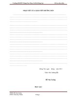
When numbering female and male connectors, refer to the numbering order in the following table. Some connectors may not follow this method of numbering order.
3 2 1
8 7 6 5 4
<sub>1 2 3 4 5 </sub> <sub>6 7 8 9 10 </sub>11 12 13 1 15 16 17 18 1 20 21 22
</div><span class="text_page_counter">Trang 5</span><div class="page_container" data-page="5">UNLESS OTHERWISE STATED, ALL CONNECTOR VIEWS ARE FROM THE TERMINAL SIDE OF THE CONNECTOR.
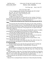
</div><span class="text_page_counter">Trang 6</span><div class="page_container" data-page="6">A broken line indicates only part of the component is shown.
This diode allows current to flow only in the direction of the arrow.
Fuse and Fusible link
This means power is supplied with the ignition on position.
The name of the component appears next to its upper right
X <sup>This means the short bar </sup> connects to other fuses.
function follow its
This means the connector con- nects directly to the component.
Circuit Breaker
This indicates the connector connects to a lead (pigtail), wired directly to the com- ponent.
Basically a reusable fuse, a circuit breaker will heat and open if too much current flows through it. Some units automatically reset when cool, others must be manu-
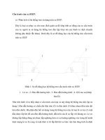
</div><span class="text_page_counter">Trang 7</span><div class="page_container" data-page="7">A wavy line means the wire is broken but
Current path is continued on the same page or another page. The arrow shows the direction look for the "A" in the marked
Where separate wires join, only the splice is shown: for details on the additional wiring, refer to the circuit listed.
Name of Circuit
A wire connects to another circuit. The wire is shown again on that circuit which the arrow is pointing. A broken line means only some of the circuit is shown: refer to the circuit listed for the com- plete schematic.
Splices are numbered and shown as a dot with circle. The exact location and connection of these splices may vary among vehicles.
G06
Wire choices for options or dif- ferent models are labeled and shown with a "choice" bracket like this.
G06
This symbol means the end of part of the vehicle.
This ground symbol (dot and 3 lines overlapping the compo- nent) means the housing of the component is attached to a metal part of the vehicle. 0.5R
</div><span class="text_page_counter">Trang 8</span><div class="page_container" data-page="8">0.5R 0.5Y/L
0.5R 0.5Y/L
0.5B
This represents RFI (Radio Fre- quency Interference) Shielding always connected to ground.
MC01
This dashed line means the R(red) and Y/L(yellow/blue) wires are both in connector MC01.
G06
EGI002C
WIRE COLOR ABBREVIATIONS
The following abbreviations are used to identify wire colors in the circuit schematics. Symbol Color of wire Symbol Color of wire
This is a relay shown with no
INDICATOR Normally closed contact
</div><span class="text_page_counter">Trang 9</span><div class="page_container" data-page="9">