ROBOTIC SYSTEMS – APPLICATIONS, CONTROL AND PROGRAMMING doc
Bạn đang xem bản rút gọn của tài liệu. Xem và tải ngay bản đầy đủ của tài liệu tại đây (45.52 MB, 638 trang )
ROBOTIC SYSTEMS –
APPLICATIONS, CONTROL
AND PROGRAMMING
Edited by Ashish Dutta
Robotic Systems – Applications, Control and Programming
Edited by Ashish Dutta
Published by InTech
Janeza Trdine 9, 51000 Rijeka, Croatia
Copyright © 2012 InTech
All chapters are Open Access distributed under the Creative Commons Attribution 3.0
license, which allows users to download, copy and build upon published articles even for
commercial purposes, as long as the author and publisher are properly credited, which
ensures maximum dissemination and a wider impact of our publications. After this work
has been published by InTech, authors have the right to republish it, in whole or part, in
any publication of which they are the author, and to make other personal use of the
work. Any republication, referencing or personal use of the work must explicitly identify
the original source.
As for readers, this license allows users to download, copy and build upon published
chapters even for commercial purposes, as long as the author and publisher are properly
credited, which ensures maximum dissemination and a wider impact of our publications.
Notice
Statements and opinions expressed in the chapters are these of the individual contributors
and not necessarily those of the editors or publisher. No responsibility is accepted for the
accuracy of information contained in the published chapters. The publisher assumes no
responsibility for any damage or injury to persons or property arising out of the use of any
materials, instructions, methods or ideas contained in the book.
Publishing Process Manager Anja Filipovic
Technical Editor Teodora Smiljanic
Cover Designer InTech Design Team
Image Copyright sarah5, 2011. DepositPhotos
First published January, 2012
Printed in Croatia
A free online edition of this book is available at www.intechopen.com
Additional hard copies can be obtained from
Robotic Systems – Applications, Control and Programming,
Edited by Ashish Dutta
p. cm.
ISBN 978-953-307-941-7
Contents
Preface IX
Part 1 Applications 1
Chapter 1 Modular Robotic Approach in Surgical Applications –
Wireless Robotic Modules and a Reconfigurable
Master Device for Endoluminal Surgery – 3
Kanako Harada, Ekawahyu Susilo, Takao Watanabe,
Kazuya Kawamura, Masakatsu G. Fujie,
Arianna Menciassi and Paolo Dario
Chapter 2 Target Point Manipulation Inside a Deformable Object 19
Jadav Das and Nilanjan Sarkar
Chapter 3 Novel Assistive Robot for Self-Feeding 43
Won-Kyung Song and Jongbae Kim
Chapter 4 Robot Handling Fabrics Towards Sewing
Using Computational Intelligence Methods 61
Zacharia Paraskevi
Chapter 5 Robotic Systems for Radiation Therapy 85
Ivan Buzurovic, Tarun K. Podder and Yan Yu
Chapter 6 Robotic Urological Surgery:
State of the Art and Future Perspectives 107
Rachid Yakoubi, Shahab Hillyer and Georges-Pascal Haber
Chapter 7 Reconfigurable Automation of Carton Packaging
with Robotic Technology 125
Wei Yao and Jian S. Dai
Chapter 8 Autonomous Anthropomorphic Robotic System
with Low-Cost Colour Sensors
to Monitor Plant Growth in a Laboratory 139
Gourab Sen Gupta, Mark Seelye,
John Seelye and Donald Bailey
VI Contents
Part 2 Control and Modeling 159
Chapter 9 CPG Implementations for Robot Locomotion:
Analysis and Design 161
Jose Hugo Barron-Zambrano and Cesar Torres-Huitzil
Chapter 10 Tracking Control in an Upper Arm Exoskeleton
with Differential Flatness 183
E. Y. Veslin, M. Dutra, J. Slama, O. Lengerke and M. J. M. Tavera
Chapter 11 Real-Time Control in Robotic Systems 209
Alex Simpkins
Chapter 12 Robot Learning from Demonstration
Using Predictive Sequence Learning 235
Erik Billing, Thomas Hellström and Lars-Erik Janlert
Chapter 13 Biarticular Actuation of Robotic Systems 251
Jan Babič
Chapter 14 Optimization and Synthesis of a Robot Fish Motion 271
Janis Viba, Semjons Cifanskis and Vladimirs Jakushevich
Chapter 15 Modeling of Elastic Robot Joints with
Nonlinear Damping and Hysteresis 293
Michael Ruderman
Chapter 16 Gravity-Independent Locomotion: Dynamics and
Position-Based Control of Robots on Asteroid Surfaces 313
Marco Chacin and Edward Tunstel
Chapter 17 Kinematic and Inverse Dynamic Analysis of a
C5 Joint Parallel Robot 339
Georges Fried, Karim Djouani and Amir Fijany
Chapter 18 Utilizing the Functional Work Space Evaluation Tool
for Assessing a System Design
and Reconfiguration Alternatives 361
A. Djuric and R. J. Urbanic
Chapter 19 Requirement Oriented Reconfiguration
of Parallel Robotic Systems 387
Jan Schmitt, David Inkermann, Carsten Stechert,
Annika Raatz and Thomas Vietor
Part 3 Vision and Sensors 411
Chapter 20 Real-Time Robotic Hand Control Using Hand Gestures 413
Jagdish Lal Raheja, Radhey Shyam,
G. Arun Rajsekhar and P. Bhanu Prasad
Contents VII
Chapter 21 Robotics Arm Visual Servo: Estimation of Arm-Space
Kinematics Relations with Epipolar Geometry 429
Ebrahim Mattar
Chapter 22 Design and Construction of an Ultrasonic Sensor
for the Material Identification in Robotic Agents 455
Juan José González España, Jovani Alberto Jiménez Builes
and Jaime Alberto Guzmán Luna
Part 4 Programming and Algorithms 471
Chapter 23 Robotic Software Systems: From Code-Driven
to Model-Driven Software Development 473
Christian Schlegel, Andreas Steck and Alex Lotz
Chapter 24 Using Ontologies for Configuring Architectures
of Industrial Robotics in Logistic Processes 503
Matthias Burwinkel and Bernd Scholz-Reiter
Chapter 25 Programming of Intelligent Service Robots
with the Process Model “FRIEND::Process”
and Configurable Task-Knowledge 529
Oliver Prenzel, Uwe Lange, Henning Kampe,
Christian Martens and Axel Gräser
Chapter 26 Performance Evaluation of Fault-Tolerant Controllers in
Robotic Manipulators 553
Claudio Urrea, John Kern
and Holman Ortiz
Chapter 27 An Approach to Distributed
Component-Based Software for Robotics 571
A. C. Domínguez-Brito, J. Cabrera-Gámez, J. D. Hernández-Sosa,
J. Isern-González and E. Fernández-Perdomo
Chapter 28 Sequential and Simultaneous Algorithms to Solve
the Collision-Free Trajectory Planning Problem for
Industrial Robots – Impact of Interpolation Functions and the
Characteristics of the Actuators on Robot Performance 591
Francisco J. Rubio, Francisco J. Valero,
Antonio J. Besa and Ana M. Pedrosa
Chapter 29 Methodology for System Adaptation
Based on Characteristic Patterns 611
Eva Volná, Michal Janošek, Václav Kocian,
Martin Kotyrba and Zuzana Oplatková
Preface
Over the last few decades the focus of robotics research has moved beyond the
traditional area of industrial applications to newer areas, including healthcare and
domestic applications. These newer applications have given a strong impetus to the
development of advanced sensors, control strategies and algorithms. The first section
of this book contains advanced applications of robotics in surgery, rehabilitation,
modular robotics among others. This is followed by sections on control and sensors,
while the fourth section is devoted to robot algorithms.
I would like to thank all the authors for entrusting us with their work and specially the
editorial members of InTech publishing.
Dr. Ashish Dutta
Department of Mechanical Engineering
Indian Institute of Technology, Kanpur
India
Part 1
Applications
1
Modular Robotic Approach
in Surgical Applications
– Wireless Robotic Modules and a
Reconfigurable Master Device
for Endoluminal Surgery –
Kanako Harada, Ekawahyu Susilo, Takao Watanabe, Kazuya Kawamura,
Masakatsu G. Fujie, Arianna Menciassi and Paolo Dario
1
The University of Tokyo
2
Scuola Superiore Sant’Anna
3
Italian Institute of Technology
4
Waseda University
1,4
Japan
2,3
Italy
1. Introduction
The trend in surgical robots is moving from traditional master-slave robots to miniaturized
devices for screening and simple surgical operations (Cuschieri, A. 2005). For example,
capsule endoscopy (Moglia, A. 2007) has been conducted worldwide over the last five years
with successful outcomes. To enhance the dexterity of commercial endoscopic capsules,
capsule locomotion has been investigated using legged capsules (Quirini, M. 2008) and
capsules driven by external magnetic fields (Sendoh, M. 2003; Ciuti, G. 2010; Carpi, F. 2009).
Endoscopic capsules with miniaturized arms have also been studied to determine their
potential for use in biopsy (Park, S K. 2008). Furthermore, new surgical procedures known
as natural orifice transluminal endoscopic surgery (NOTES) and Single Port Access surgery
are accelerating the development of innovative endoscopic devices (Giday, S. 2006; Bardaro,
S.J. 2006). These advanced surgical devices show potential for the future development of
minimally invasive and endoluminal surgery. However, the implementable functions in
such devices are generally limited owing to space constraints. Moreover, advanced capsules
or endoscopes with miniaturized arms have rather poor dexterity because the diameter of
such arms must be small (i.e. a few millimeters), which results in a small force being
generated at the tip.
A modular surgical robotic system known as the ARES (Assembling Reconfigurable
Endoluminal Surgical system) system has been proposed based on the aforementioned
motivations (Harada, K. 2009; Harada, K. 2010; Menciassi, A. 2010). The ARES system is
designed for screening and interventions in the gastrointestinal (GI) tracts to overcome the
intrinsic limitations of single-capsules or endoscopic devices. In the proposed system,
Robotic Systems – Applications, Control and Programming
4
miniaturized robotic modules are ingested and assembled in the stomach cavity. The
assembled robot can then change its configuration according to the target location and task.
Modular surgical robots are interesting owing to their potential for application as self-
reconfigurable modular robots and innovative surgical robots. Many self-reconfigurable
modular robots have been investigated worldwide (Yim, M. 2007; Murata, S. 2007) with the
goal of developing systems that are robust and adaptive to the working environment. Most
of these robots have been designed for autonomous exploration or surveillance tasks in
unstructured environments; therefore, there are no strict constraints regarding the number
of modules, modular size or working space. Because the ARES has specific applications and
is used in the GI tract environment, it raises many issues that have not been discussed in
depth in the modular robotic field. Modular miniaturization down to the ingestible size is
one of the most challenging goals. In addition, a new interface must be developed so that
surgeons can intuitively maneuver the modular surgical robot.
The purpose of this paper is to clarify the advantages of the modular approach in surgical
applications, as well as to present proof of concept of the modular robotic surgical system.
The current paper is organized as follows: Section 2 describes the design of the ARES
system. Section 3 details the design and prototyping of robotic modules, including the
experimental results. Section 4 describes a reconfigurable master device designed for the
robotic modules, and its preliminary evaluation is reported.
2. Design of the modular surgical system
2.1 Clinical indications and proposed procedures
The clinical target of the ARES system is the entire GI tract, i.e., the esophagus, stomach,
small intestine, and colon. Among GI tract pathologies that can benefit from modular
robotic features, biopsy for detection of early cancer in the upper side of the stomach (the
fundus and the cardia) was selected as the surgical task to be focused on as a first step.
Stomach cancer is the second leading cause of cancer-related deaths worldwide (World
Health Organization 2006), and stomach cancer occurring in the upper side of the stomach
has the worst outcome in terms of the 5-year survival ratio (Pesic, M. 2004). Thus, early
diagnosis of cancer utilizing an advanced endoluminal device may lead to better prognosis.
The stomach has a large volume (about 1400 ml) when distended, which provides working
space to assemble the ingested robotic modules and change the topology of the assembled
robot inside (i.e. reconfiguration). Each robotic module should be small enough to be
swallowed and pass through the whole GI tract. Because the size of the commercial
endoscopic capsules (11 mm in diameter and 26 mm in length (Moglia, A. 2007)) has already
been shown to be acceptable for the majority of patients as an ingestible device, each module
needs to be miniaturized to this size before being applied to clinical cases.
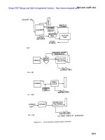
The surgical procedures proposed for the ARES system (Harada, K. 2010) are shown in Fig.
1. Prior to the surgical procedure, the patient drinks a liquid to distend the stomach to a
volume of about 1400 ml. Next, the patient ingests 10-15 robotic modules that complete the
assembly process before the liquid naturally drains away from the stomach in 10-20
minutes. The number of the modules swallowed depends on the target tasks and is
determined in advance based on the pre-diagnosis. Magnetic self-assembly in the liquid
using permanent magnets was selected for this study since its feasibility has already been
demonstrated (Nagy, Z. 2007). Soon after the assembly, the robot configures its topology
Modular Robotic Approach in Surgical Applications
– Wireless Robotic Modules and a Reconfigurable Master Device for Endoluminal Surgery –
5
according to preoperative planning by repeated docking and undocking of the modules (the
undocking mechanism and electrical contacts between modules are necessary for
reconfiguration, but they have not been implemented in the presented design). The robotic
modules are controlled via wireless bidirectional communication with a master device
operated by the surgeon, while the progress in procedure is observed using intraoperative
imaging devices such as fluoroscopy and cameras mounted on the modules. After the
surgical tasks are completed, the robot reconfigures itself to a snake-like shape to pass
through the pyloric sphincter and travel to examine the small intestine and the colon, or it
completely disassembles itself into individual modules so that it can be brought out without
external aid. One of the modules can bring a biopsy tissue sample out of the body for
detailed examination after the procedure is complete.
Fig. 1. Proposed procedures for the ARES system
2.2 Advantages of the modular approach in surgical applications
The modular approach has great potential to provide many advantages to surgical
applications. These advantages are summarized below using the ARES system as shown in
Fig.2. The numbering of the items in Fig.2 is correlated with the following numbering.
i. The topology of the modular surgical robot can be customized for each patient
according to the location of the disease and the size of the body cavity in which the
modular robot is deployed. A set of functional modules such as cameras, needles and
forceps can be selected for each patient based on the necessary diagnosis and surgical
operation.
ii. The modular approach facilitates delivery of more components inside a body cavity
that has small entrance/exit hole(s). As there are many cavities in the human body, the
modular approach would benefit treatment in such difficult-to-reach places. Because
Robotic Systems – Applications, Control and Programming
6
several functional modules can be used simultaneously, the modular robot may
perform rather complicated tasks that a single endoscopic capsule or an endoscopic
device is not capable of conducting. For example, if more than two camera modules are
employed, the surgeon can conduct tasks while observing the site from different
directions.
iii. Surgical tools of relatively large diameter can be brought into the body cavity.
Conventionally, small surgical forceps that can pass through an endoscopic channel of a
few millimeters have been used for endoluminal surgery. Conversely, surgical devices
that have the same diameter as an endoscope can be used in the modular surgical
system. Consequently, the force generated at the tip of the devices would be rather
large, and the performance of the functional devices would be high.
iv. The surgical system is more adaptive to the given environment and robust to failures.
Accordingly, it is not necessary for the surgical robot to equip all modules that might be
necessary in the body because the surgeons can decide whether to add modules with
different functionalities, even during the surgical operation. After use, the modules can
be detached and discarded if they are not necessary in the following procedures.
Similarly, a module can be easily replaced with a new one in case of malfunction.
As these advantages suggest, a modular surgical robot would be capable of achieving rather
complicated tasks that have not been performed using existing endoluminal surgical
devices. These advantages are valid for modular robots that work in any body cavity with a
small entrance and exit. Moreover, this approach may be introduced to NOTES or Single
Port Access surgery, in which surgical devices must reach the abdominal cavity through a
small incision.
In Section 3, several robotic modules are proposed, and the performance of these modules is
reported to show the feasibility of the proposed surgical system.
(i)
(ii)
(iii)
(iv)
Fig. 2. Advantages of the modular approach in surgical applications
Modular Robotic Approach in Surgical Applications
– Wireless Robotic Modules and a Reconfigurable Master Device for Endoluminal Surgery –
7
3. Robotic modules
3.1 Design and prototyping of the robotic modules
Figure 3 shows the design and prototypes of the Structural Module and the Biopsy Module
(Harada, K. 2009, Harada, K. 2010). The Structural Module has two degrees of freedom (±90°
of bending and 360° of rotation). The Structural Module contains a Li-Po battery (20 mAh,
LP2-FR, Plantraco Ltd., Canada), two brushless DC geared motors that are 4 mm in
diameter and 17.4 mm in length (SBL04-0829PG337, Namiki Precision Jewel Co. Ltd., Japan)
and a custom-made motor control board capable of wireless control (Susilo, E. 2009). The
stall torque of the selected geared motor is 10.6 mNm and the speed is 112 rpm when
controlled by the developed controller. The bending mechanism is composed of a worm and
a spur gear (9:1 gear reduction), whereas the rotation mechanism is composed of two spur
gears (no gear reduction). All gears (DIDEL SA, Switzerland) were made of nylon, and they
were machined to be implemented in the small space of the capsule. Two permanent
magnets (Q-05-1.5-01-N, Webcraft GMbH, Switzerland) were attached at each end of the
module to help with self-alignment and modular docking. The module is 15.4 mm in
diameter and 36.5 mm in length; it requires further miniaturization before clinical
application. The casing of the prototype was made of acrylic plastic and fabricated by 3D
rapid prototyping (Invison XT 3-D Modeler, 3D systems, Inc., USA). The total weight is 5.6 g.
Assuming that the module would weigh 10 g with the metal chassis and gears, the
maximum torque required for lifting two connected modules is 5.4 mNm for both the
bending DOF and rotation DOF. Assuming that the gear transmission efficiency for the
bending mechanism is 30%, the stall torque for the bending DOF is 28.6 mNm. On the other
hand, the stall torque for the rotation DOF is 8.5 mNm when the transmission efficiency for
the rotation mechanism is 80%. The torque was designed to have sufficient force for surgical
operation, but the transmission efficiency of the miniaturized plastic gears was much
smaller than the theoretical value as explained in the next subsection.
• Controller
The aforementioned brushless DC motor came with a dedicated motor driving board
(SSD04, Namiki Precision Jewel Co., Ltd., 19.6 mm × 34.4 mm × 3 mm). This board only
allows driving of one motor; hence, two boards are required for a robotic module with 2
DOFs. Because there was not sufficient space for the boards in the robotic module, a custom
made high density control board was designed and developed in-house. This control board
consisted of one CC2430 microcontroller (Texas Instrument, USA) as the main wireless
controller and three sets of A3901 dual bridge motor drivers (Allegro MicroSystem, Inc.,
USA). The fabricated board is 9.6 mm in diameter, 2.5 mm in thickness and 0.37 g in weight,
which is compatible with swallowing. The A3901 motor driver chip was originally intended
for a brushed DC motor, but a software commutation algorithm was implemented to control
a brushless DC motor as well. An IEEE 802.15.4 wireless personal area network (WPAN)
was introduced as an embedded feature (radio peripheral) of the microcontroller. The
implemented algorithm enables control of the selected brushless DC motor in Back Electro-
Motive Force (BEMF) feedback mode or slow speed stepping mode. When the stepping
mode is selected, the motor can be driven with a resolution of 0.178º.
For the modular approach, each control board shall be equipped with a wired locating
system for intra-modular communication in addition to the wireless communication. Aside
from wireless networking, the wired locating system, which is not implemented in the
presented design, would be useful for identification of the sequence of the docked modules
Robotic Systems – Applications, Control and Programming
8
in real time. The wired locating system is composed of three lines, one for serial multidrop
communication, one for a peripheral locator and one as a ground reference. When the
modules are firmly connected, the intra-modular communication can be switched from
wireless to wired to save power while maintaining the predefined network addresses. When
one module is detached intentionally or by mistake, it will switch back to wireless mode.
• Battery
The battery capacity carried by each module may differ from one to another (e.g. from 10
mAh to 50 mAh) depending on the available space inside the module. For the current
design, a 20 mAh Li-Po battery was selected. Continuous driving of the selected motor on its
maximum speed using a 20 mAh Li-Po battery was found to last up to 17 minutes. A
module does not withdraw power continuously because the actuation mechanisms can
maintain their position when there is no current to the motor owing to its high gear
reduction (337:1). A module consumes power during actuation, but its power use is very
low in stand-by mode.
• Biopsy Module
The Biopsy Module is a Functional Module that can be used to conduct diagnosis. The
grasping mechanism has a worm and two spur gears, which allows wide opening of the
grasping parts. The grasping parts can be hidden in the casing at the maximum opening to
prevent tissue damage during ingestion. The motor and other components used for the
Biopsy Module are the same as for the Structural Module. The brushless DC geared motors
(SBL04-0829PG337, Namiki Precision Jewel Co. Ltd., Japan), the control board, a worm gear
and two spur gears (9:1 gear reduction) were implemented in the Biopsy Module. A
permanent magnet (Q-05-1.5-01-N, Webcraft GMbH, Switzerland) was placed at one side to
be connected to another Structural Module.
Fig. 3. Design and prototypes of the structural module (left) and the biopsy module (right)
Modular Robotic Approach in Surgical Applications
– Wireless Robotic Modules and a Reconfigurable Master Device for Endoluminal Surgery –
9
The Biopsy Module can generate a force of 7.1 N at its tip, and can also open the grasping
parts to a width of 19 mm with an opening angle of 90 degrees. These values are much
larger than those of conventional endoscopic forceps, which are 2-4 mm in diameter. As a
demonstration, Figure 3 shows the Biopsy Module holding a coin weighing 7.5 g.
In conventional endoscopy, forceps are inserted through endoscopic channels that are
parallel to the direction of the endoscopic view, which often results in the forceps hiding the
target. Conversely, the Biopsy Module can be positioned at any angle relative to the
endoscopic view owing to the modular approach, thereby allowing adequate approach to
the target.
3.2 Performance of the Structural Module
The mechanical performance of the bending and rotation DOFs of the Structural Module
was measured in preliminary tests (Menciassi, A. 2010), and the results are summarized in
Fig.4. The bending angle was varied by up to ± 90° in steps of 10° three times in succession.
The measured range of the bending angle was -86.0° to +76.3°, and the maximum error was
15.8°. The rotation angle was increased from 0° to 180° in steps of 45° three times in
succession, and the measured range of the rotational angle was between 0° and 166.7° with a
maximum error of 13.3°. The difference between the driven angle and the measured angle
was due to backlash of the gears and the lack of precision and stiffness of the casing made
by 3D rapid prototyping. Regardless of the errors and the hysteresis, the repeatability was
sufficient for the intended application for both DOFs. These results indicate that the
precision of each motion can be improved by changing the materials of the gears and the
casing. Since the motor can be controlled with a resolution of 0.178°, very precise surgical
tasks can be achieved using different manufacturing processes.
Measured Angle (deg.)
Commanded Angle (deg.)
0
45
90
135
180
180
135
9045
0
45
90
-45
-90
Measured Angle (deg.)
45 90-45
-90
Commanded Angle (deg.)
0
Fig. 4. Bending angle measurement (left), rotation angle measurement (middle), and torque
measurement (right) (Menciassi, A. 2010)
In addition to the angle measurements, both bending and rotation torque were measured.
The torque was measured by connecting cylindrical parts with permanent magnets at both
ends until the bending/rotational motion stopped. The length and weight of each cylinder
was designed in advance, and several types of cylinders were prepared. The measured
bending torque was 6.5 mNm and the rotation torque was 2.2 mNm. The figure also shows
one module lifting up two modules attached to its bending mechanism as a demonstration.
The performance in terms of precision and generated torque, which are very important for
reconfiguration and surgical tasks, was sufficient; however, the precision was limited owing
Robotic Systems – Applications, Control and Programming
10
to the aforementioned fabrication problems. The thin walls of the casing made of acrylic
plastic were easily deformed, which caused friction between the parts. The casing made of
metal or PEEK and tailor-made metal gears with high precision will improve the mechanism
rigidity and performance, thus producing the optimal stability.
3.3 Possible designs of robotic modules
Figure 5 shows various designs of robotic modules that can be implemented in the modular
surgical robot. The modules can be categorized into three types: structural modules,
functional modules, and other modules. Structural modules are used to configure a robotic
topology. Functional modules are used for diagnosis or intervention, while other modules
can be added to enhance the performance and robustness of the robotic system. Obviously,
an assembled robot made of different types of modules (i.e. a robot with high heterogeneity)
may provide high dexterity, but the self-assembly in the stomach and control of the modules
would become more difficult. To optimize the level of heterogeneity, self-assembly of the
robotic modules must be developed so that the reconfiguration of the robotic topology
following the self-assembly can be planned in advance. Employing pre-assembled modular
arms or tethered modules can be another option to facilitate assembly in a body cavity;
however, this would require further anesthesia, and it would hinder the promotion of
massive screening.
Fig. 5. Various designs of the robotic modules
Modular Robotic Approach in Surgical Applications
– Wireless Robotic Modules and a Reconfigurable Master Device for Endoluminal Surgery –
11
4. Reconfigurable master device
4.1 Design and prototyping of the reconfigurable master device
One main advantage of using a modular approach in surgical applications is the adaptivity
to the given environment as mentioned in Section 2.2. Wherever the robotic platform is
deployed in the GI tract, the robotic topology can be changed based on preoperative plans
or the in-situ situation to fit in any particular environment. This dynamic changing and
reshaping of the robotic topology should be reflected on the user interface. Since it is
possible for a robotic topology to have redundant DOFs, the master device for the modular
surgical system needs to be able to handle the redundancy that is inherent to modular
robots. Based on these considerations, we propose a reconfigurable master device that
resembles the robotic platform (Fig.6). When the assembled robot changes its topology, the
master device follows the same configuration. The robotic module shown in Fig. 6 has a
diameter of 15.4 mm, while a module of the reconfigurable master device has a diameter of
30 mm. The master modules can be easily assembled or disassembled using set screws, and
it takes only a few seconds to connect one module to another.
Each robotic module is equipped with two motors as described in the previous section; thus,
each master module is equipped with two potentiometers (TW1103KA, Tyco Electronics)
that are used as angular position sensors. Calculating the angular position of each joint of
the reconfigurable master device is quite straightforward. A common reference voltage is
sent from a data acquisition card to all potentiometers, after which the angular position can
be calculated from the feedback readings. Owing to the identical configuration, the angle of
each joint of the robotic modules can be easily determined, even if the topology has
redundancy.
Fig. 6. Robotic modules (top line) and the reconfigurable master device (bottom line): one
module (left), assembled modules (middle) and prototypes (right)
Robotic Systems – Applications, Control and Programming
12
The advantages of the proposed master device include intuitive manipulation. For example,
the rotational movement of a structural module used to twist the arm is limited to ± 180°,
and the master module also has this limitation. This helps surgeons intuitively understand
the range of the motion and the reachable working space of the modules. Using a
conventional master manipulator or an external console, it is possible that the slave
manipulator cannot move owing to its mechanical constraints, while the master manipulator
can still move. However, using the proposed master device, the surgeon can intuitively
understand the mechanical constraints by manipulating the master device during
practice/training. Furthermore, the position of the master arm can indicate where the
robotic modules are, even if they are outside of the camera module's view. These
characteristics increase the safety of the operation. This feature is important because the
entire robotic system is placed inside the body. In other surgical robotic systems, the
position or shape of the robotic arms is not important as they are placed outside of the body
and can be seen during operation. Unlike other master devices, it is also possible for two or
more surgeons to move the reconfigurable master device together at the same time using
multi arms with redundant DOFs.
4.2 Evaluation
A simulation-based evaluation setup was selected to simplify the preliminary evaluation of
the feasibility of the reconfigurable master device. The authors previously developed the
Slave Simulator to evaluate workloads for a master-slave surgical robot (Kawamura, K.
2006). The Slave Simulator can show the motion of the slave robot in CG (Computer
Graphics), while the master input device is controlled by an operator. Because the simulator
can virtually change the parameters of the slave robot or its control, it is easy to evaluate the
parameters as well as the operability of the master device. This Slave Simulator was
appropriately modified for the ARES system. The modified Slave Simulator presents the CG
models of the robotic modules to the operator. The dimension and DOFs of each module in
CG were determined based on the design of the robotic modules. The angle of each joint is
given by the signal from the potentiometers of the reconfigurable master device, and the
slave modules in CG move in real time to reproduce the configuration of the master device.
This Slave Simulator is capable of altering joint positions and the number of joints of the
slave arms in CG so that the workspace of the reconfigurable master device can be
reproduced in a virtual environment for several types of topologies. The simulator is
composed of a 3D viewer that uses OpenGL and a physical calculation function. This
function was implemented to detect a collision between the CG modules and an object
placed in the workspace.
To simplify the experiments to evaluate the feasibility of the proposed master device and
usefulness of the developed simulator, only one arm of the reconfigurable master device
was used. Three topologies that consist of one Biopsy Module and one or two Structural
Module(s) were selected as illustrated in Fig.7. Topology I consists of a Structural Module
and a Biopsy Module, and the base is fixed so that the arm appears with an angle of 45
degrees. One Structural Module is added to Topology I to configure Topology II, and
Topology III is identical to Topology II, but placed at 0 degrees. Both Topology II and
Topology III have redundant DOFs. The projection of the workspace of each arm and the
shared workspace are depicted in Fig.8. A target object on which the arm works in the
experiments must be placed in this shared area, which makes it easy to compare topologies.
Modular Robotic Approach in Surgical Applications
– Wireless Robotic Modules and a Reconfigurable Master Device for Endoluminal Surgery –
13
A bar was selected as the target object instead of a sphere because the height of the collision
point is different for each topology when the object appears in the same position in the 2D
plane.
The experiment was designed so that a bar appears at random in the shared workspace. The
bar represents a target area at which the Biopsy Module needs to collect tissue samples, and
this experiment is a simple example to select one topology among three choices given that
the arm can reach the target. We assumed that this choice may vary depending on the user,
and this experiment was designed to determine if the reconfigurability of the master device,
i.e. customization of the robot, provides advantages and improves performance.
Topology I Topology II Topology III
Combination
Master
device
Simulator
Fig. 7. Three topologies used in the experiments
During the experiment, the operator of the reconfigurable master device could hear a
beeping sound when the distal end of the arm (i.e. the grasping part of the biopsy module)
touched the bar. The task designed for the experiments was to move the arm of the
reconfigurable master device as quickly as possible, touch the bar in CG, and then maintain
its position for three seconds. The plane in which the bar stands is shown in grids (Fig.9),
and the operator obtains 3D perception by observing these grids. The plane with the grids is
the same for all topologies. The angle of the view was set so that the view is similar to that
from the camera module in Fig.6.
Five subjects (a-e) participated in the experiments, none of whom were surgeons. Each
subject was asked to freely move the master device to learn how to operate it; however, this
practice was allowed for one minute before starting the experiments. Each subject started
from Topology I, then tested Topology II and finally Topology III. The time needed to touch
the bar and maintain it for three seconds was measured. This procedure was repeated ten
times for each topology with a randomized position of the bar. During the procedure, the
bar appeared at random; however, it always appeared in the shared workspace to ensure
Robotic Systems – Applications, Control and Programming
14
that the arm could reach it. After finishing the experiment, the subjects were asked to fill in a
questionnaire (described below) for each topology. The subjects were also asked which
topology they preferred.
Fig. 8. Workspace of each topology and the shared workspace
Fig. 9. Simulator and the master device during one test
A NASA TLX questionnaire (NASA TLX (website)) was used to objectively and
quantitatively evaluate the workload that the subjects felt during the experiments. This
method has versatile uses, and we selected this method also because it was used to evaluate
the workload in a tele-surgery environment (Kawamura, K. 2006). This method evaluates
Metal Demand, Physical Demand, Temporal Demand, Performance, Effort and Frustration,
and gives a score that represents the overall workload that the subject felt during the task.
4.3 Results
The time spent conducting the given task, the workload score evaluated using the NASA
TLX questionnaire and the preference of the topology determined by the subjects are
Modular Robotic Approach in Surgical Applications
– Wireless Robotic Modules and a Reconfigurable Master Device for Endoluminal Surgery –
15
summarized in Table 1. For each item, a smaller value indicates a more favorable evaluation
by the subject.
Considering the results of the time and workload score, Topology II was most difficult. The
difference between Topology I and III was interesting. Two of the subjects ((b) and (c))
preferred Topology I, which did not have a redundant DOF. Conversely, three of the
subjects ((a), (d) and (e)) preferred Topology III because they could select the path to reach
the target owing to the redundant DOF. The average scores of the NASA TLX parameters
shown in Fig.10 suggest that the Physical Demand workload was high for Topology I, while
the Effort workload was high for Topology III.
The two subjects who preferred Topology I rather than Topology III claimed that it was not
easy to determine where the bar was located when Topology III was used owing to the lack
of 3D perception. In addition, they reported that the bar seemed to be placed far from the
base. However, the bar appeared randomly, but in the same area; therefore, the bar that
appeared in the experiment that employed Topology III was not placed farther from the
base when compared to the experiments that used Topology I or Topology II. Accordingly,
these two subjects may have had difficulty obtaining 3D perception from the gridded plane.
In Topology III, the arm was partially out of view in the initial position; thus, the operator
needed to obtain 3D perception by seeing the grids. It is often said that most surgeons can
obtain 3D perception even if they use a 2D camera, and our preliminary experimental results
imply that this ability might differ by individual. Some people appear to obtain 3D perception
primarily by seeing the relative positions between the target and the tool they move.
Redundant DOFs may also be preferred by operators with better 3D perception capability.
Although the experiments were preliminary, there must be other factors that accounted for
the preference of the user. Indeed, it is likely that the preferable topology varies depending
on the user, and the developed simulator would be useful to evaluate these variations. The
proposed reconfigurable master device will enable individual surgeons to customize the
robot and interface as they prefer.
Topology
Subject
Average
a b c d e
Time (s)
I 5.7 4.1 4.0 5.8 5.0 4.9
II 7.6 6.2 4.8 5.5 6.7 6.1
III 4.9 4.3 5.6 4.4 4.7 4.8
Work Load:
NASA-TLX
Score
I 30.7 11.3 28.3 32.0 73.3 35.1
II 47.6 26.7 28.0 53.0 68.3 44.7
III 37.0 5.0 24.3 14.3 61.3 28.4
Preference
I 3 1 1 3 3 2.2
II 2 3 2 2 2 2.2
III 1 2 3 1 1 1.6
Table 1. Experimental results