Petri Nets Applications_2 potx
Bạn đang xem bản rút gọn của tài liệu. Xem và tải ngay bản đầy đủ của tài liệu tại đây (25.88 MB, 400 trang )
ModellingandFaultDiagnosisbymeansofPetriNets.UnmannedAerialVehicleApplication 353
ModellingandFaultDiagnosisbymeansofPetriNets.UnmannedAerial
VehicleApplication
MiguelTrigos,AntonioBarrientos,JaimedelCerroandHermesLópez
X
Modelling and Fault Diagnosis by means of
Petri Nets. Unmanned Aerial Vehicle Application
Miguel Trigos
2,1
, Antonio Barrientos
1
,
Jaime del Cerro
1
and Hermes López
2
1
Universidad Politécnica de Madrid, (Robotics and Cybernetics Group)
2
Universidad Santo Tomas de Bucaramanga, (Mechatronics Engineering Faculty)
Spain-Colombia
1. Introduction
The safe and reliable operation of technical systems is very important not only for the
protection of humans but also for the protection of environment and economic investments.
The proper functioning of these systems has profound impact on production costs and
product quality. Early fault
1
detection is critical in preventing a deterioration of behavior,
damage to equipment or human life. The diagnosis must then help to make correct decisions
in emergency actions and repairs.
This necessity has motivated the Robotics and Cybernetics group of Universidad Politécnica
de Madrid to develop a methodology for developing embedded FD systems.
Techniques of Fault Diagnosis (FD) have been usually developed within a large area of
research at the intersection of control and systems engineering, Artificial Intelligence,
Mathematics and Statistics applied to fields such as Chemical, Electrical, Mechanical and
Aerospace Engineering.
Due to FD methodology was initially developed for discrete event systems (DES’s), an
adaptation to the hybrids (composed of discrete and continuous processes) has been
required.
Petri Nets (PN) have been the tool used to build the model and diagnoser, due to it is an
excellent platform, which solves the limitations of combinational explosion presented in
previous work of FD using to model finite state machines (FSM).
The FD algorithm presented here, begins with the definition of the PN model of each one of
the system components, which must integrate the normal and failure operation modes.
Next step consist of building the general integration model of the system, it will support the
construction of the diagnoser, who is responsible for overseeing the system in an online way
1
Often, the term failure is used to denote a complete operational breakdown, whereas the
term fault is used to denote any abnormal change in behavior; in this chapter we will use the
two terms synonymously.
18
PetriNets:Applications354
has one major limitation is that the number of states of the composition model, is given by
the multiplication of the events of the system components, leading to if the components of
systems increases, this construction is impossible of realize. In general, this methodology
has several drawbacks: it is rigid (the failures have to happen in a certain way), only allows
the diagnosis of one fault, for multiple failures, simultaneous and dependents can not be
applied, and finally the biggest disadvantage is combinational explosion, this means that
only can be applied to small processes, when the complexity of the process increases, it is
impossible to apply this methodology.
Other contributions in line with DES’s are developed by (Giua & Seatzu, 2005) (Chung &
Jeng, 2003) (Ushio et al., 1998). These researchers have in their development a combination
of tools, the model built with PN and diagnosis made with FSM's. To work (Chung & Jeng,
2003) (Ushio et al., 1998), the disadvantages given by (Sampath et al., 1995) are held almost
entirely. (Giua & Seatzu, 2005) In the construction of the diagnoser have a better harnessing
the mathematics power of PN, but ultimately the problem of combinatorial explosion is
presented yet. It also presents the work of (Ramirez et al., 2007), the model is made with PN
Interpreted, gives a better use to mathematic power of PN; Presents a systematic algorithm
for constructing the model and diagnoser, its diagnosis is difficult because only identify a
fault and its model of PN enters a sink state (deadlock). Finally, there is research (Genc &
Lafortune, 2006), it makes fault diagnosis using PN with limited places, this technique is
complex to implement and less possible to apply to industrial processes with medium level
of complexity.
In Fault Diagnosis of Hybrid Systems, investigations can be classified according to the
techniques used in its implementation, there are tools where already have made high
progress, such as: Hybrid Automata, Hybrid Petri nets, among others, and other have not
defined a specific technique and on the contrary, do FD by mean of combining different
techniques.
The work cited by (Krogh, 2002) is a document that diagnosis dynamic complex systems,
which continuous systems are examining with Supervisory Controller, experimenting
partial or final failures on the devices of the system. (Zhao et al., 2005) conducted one of the
most interesting applications developed to date in FD of hybrid systems; all work is carried
out in the paper feeder of a Xerox printer. His contributions are great because it makes a
hybrid integration of discrete and continuous FD techniques: Hybrid automata, Timed Petri
Nets, Fault Trees and signal processing techniques that together solve a problem of
diagnosis. (Narasimhan et al., 2000) works FD on hybrid systems combining model-based
diagnosis with signal processing. (Fourlas et al., 2005) discusses the notion of diagnosis of
hybrid systems in the workspace of Hybrid Automata, other works that guide its
development from DES’s to Hybrid Systems are the (Cassandra, 2002) and (Krogh, 2002).
They base their work on (Henzinger, 1996) and discrete analyze and hybrid system control.
In the area of fault diagnosis of UAS (Unmanned Aerial Systems), according to (Hayhurst et
al., 2006), the dangers that may represent an unmanned aircraft, is related to three key
domains: design domain, flight crew domain and operational domain. In these domains can
reveal hazards such as: impacts on ground with collateral damage to persons and property,
and midair collision with manned aircraft or another UAS. Although at first instance it
seems that the problems are the same as a manned aircraft, it must need great attention to
the risks involved in the separation of the cabin of the aircraft.
and informing the operator of the presence of a fault. The construction is a simple and
robust process; its main advantages are the simultaneous detection of failures and the
flexibility to expand its application to another components.
This tool has been implemented in several industrial applications, such as a ventilation
system, heating and air conditioning systems (Trigos & Garcia, 2008 (A)), and liquids
packaging processes (Trigos & Garcia, 2008 (B)) among others, but in this chapter, it is
applied to a novel application: “Unmanned Aerial Vehicle (UAV)”.
The proposed FD method is suitable for this application due to the hybrid nature of the
unmanned aerial vehicles (UAV) and their high complexity, which requires a fault detection
system.
The new legislative trends in the use of UAS (Unmanned Aerial System) will probably
require having security systems where FD techniques are applicable. Furthermore, based on
the report about reliability of UAVs in the military field of United States (Office of the
Secretary of Defense USA, 2003), can be summarized that the UAVs are highly vulnerable
not only to unexpected mishaps on the devices that make up the system (aircraft and
control station) but also to the test environment.
Usually, the causes of these problems are unknown, but in addition to this, there is a lack of
methods to prevent these failures. This problem is intrinsic to the UAV due to they have
strong mechanical requirements and the consequences of a small failure can be enormous in
comparison to ground vehicles.
In section 2 of this chapter, a state of the art about fault diagnosis is presented, starting with
the work developed in the context of discrete event systems, connecting to continuous and
finally hybrid systems. Section 3 summarizes the theory of Petri nets, due to they are
intensely used in the work. Section 4 describes the methodology for building the model and
the diagnoser by using PN applied to FD hybrid systems.
The application used to deploy the FD method is an unmanned aerial vehicle which is
described in Section 5; it highlights important concepts in the operation of UAVs and data
reliability in the military. After that, a model and diagnoser are constructed. Finally, section
6 sets out the conclusions of this investigation of FD in the field of UAVs, which is an
excellent platform for implementing the tool.
2. State of the Art of Fault Diagnosis
The fault diagnosis is one of the major areas of research in Automatic and Control
Engineering. Automatic processes are more demanding and complex, by this reason, fault
diagnosis is analyzed from different fields. Algorithms for detection and isolation of faults
can be classified in two major groups: related to the dynamics involved in the process and
algorithms applied to processes of continuous and discrete dynamics. Real processes are
composed of elements of the two dynamics, continuous and discrete, known as systems or
processes hybrid. To expand the state of the art of researches in continuous systems,
consulting (Venkatasubramanian et al., 2003).
In fault diagnosis of DES`s exist developments implemented by means of Regular
Languages, State Graphs, Finite State Machines (FSM's) (Sampath et al., 1995) and the most
used, Petri Nets (PN) (Ramirez et al., 2007). Also, there are researches where the benefits of
FSM's and PN are mixed (Giua & Seatzu, 2005) (Chung & Jeng, 2003) (Ushio et al., 1998).
The basis of the works mentioned below is made of FSM's (Sampath et al., 1995). This model
ModellingandFaultDiagnosisbymeansofPetriNets.UnmannedAerialVehicleApplication 355
has one major limitation is that the number of states of the composition model, is given by
the multiplication of the events of the system components, leading to if the components of
systems increases, this construction is impossible of realize. In general, this methodology
has several drawbacks: it is rigid (the failures have to happen in a certain way), only allows
the diagnosis of one fault, for multiple failures, simultaneous and dependents can not be
applied, and finally the biggest disadvantage is combinational explosion, this means that
only can be applied to small processes, when the complexity of the process increases, it is
impossible to apply this methodology.
Other contributions in line with DES’s are developed by (Giua & Seatzu, 2005) (Chung &
Jeng, 2003) (Ushio et al., 1998). These researchers have in their development a combination
of tools, the model built with PN and diagnosis made with FSM's. To work (Chung & Jeng,
2003) (Ushio et al., 1998), the disadvantages given by (Sampath et al., 1995) are held almost
entirely. (Giua & Seatzu, 2005) In the construction of the diagnoser have a better harnessing
the mathematics power of PN, but ultimately the problem of combinatorial explosion is
presented yet. It also presents the work of (Ramirez et al., 2007), the model is made with PN
Interpreted, gives a better use to mathematic power of PN; Presents a systematic algorithm
for constructing the model and diagnoser, its diagnosis is difficult because only identify a
fault and its model of PN enters a sink state (deadlock). Finally, there is research (Genc &
Lafortune, 2006), it makes fault diagnosis using PN with limited places, this technique is
complex to implement and less possible to apply to industrial processes with medium level
of complexity.
In Fault Diagnosis of Hybrid Systems, investigations can be classified according to the
techniques used in its implementation, there are tools where already have made high
progress, such as: Hybrid Automata, Hybrid Petri nets, among others, and other have not
defined a specific technique and on the contrary, do FD by mean of combining different
techniques.
The work cited by (Krogh, 2002) is a document that diagnosis dynamic complex systems,
which continuous systems are examining with Supervisory Controller, experimenting
partial or final failures on the devices of the system. (Zhao et al., 2005) conducted one of the
most interesting applications developed to date in FD of hybrid systems; all work is carried
out in the paper feeder of a Xerox printer. His contributions are great because it makes a
hybrid integration of discrete and continuous FD techniques: Hybrid automata, Timed Petri
Nets, Fault Trees and signal processing techniques that together solve a problem of
diagnosis. (Narasimhan et al., 2000) works FD on hybrid systems combining model-based
diagnosis with signal processing. (Fourlas et al., 2005) discusses the notion of diagnosis of
hybrid systems in the workspace of Hybrid Automata, other works that guide its
development from DES’s to Hybrid Systems are the (Cassandra, 2002) and (Krogh, 2002).
They base their work on (Henzinger, 1996) and discrete analyze and hybrid system control.
In the area of fault diagnosis of UAS (Unmanned Aerial Systems), according to (Hayhurst et
al., 2006), the dangers that may represent an unmanned aircraft, is related to three key
domains: design domain, flight crew domain and operational domain. In these domains can
reveal hazards such as: impacts on ground with collateral damage to persons and property,
and midair collision with manned aircraft or another UAS. Although at first instance it
seems that the problems are the same as a manned aircraft, it must need great attention to
the risks involved in the separation of the cabin of the aircraft.
and informing the operator of the presence of a fault. The construction is a simple and
robust process; its main advantages are the simultaneous detection of failures and the
flexibility to expand its application to another components.
This tool has been implemented in several industrial applications, such as a ventilation
system, heating and air conditioning systems (Trigos & Garcia, 2008 (A)), and liquids
packaging processes (Trigos & Garcia, 2008 (B)) among others, but in this chapter, it is
applied to a novel application: “Unmanned Aerial Vehicle (UAV)”.
The proposed FD method is suitable for this application due to the hybrid nature of the
unmanned aerial vehicles (UAV) and their high complexity, which requires a fault detection
system.
The new legislative trends in the use of UAS (Unmanned Aerial System) will probably
require having security systems where FD techniques are applicable. Furthermore, based on
the report about reliability of UAVs in the military field of United States (Office of the
Secretary of Defense USA, 2003), can be summarized that the UAVs are highly vulnerable
not only to unexpected mishaps on the devices that make up the system (aircraft and
control station) but also to the test environment.
Usually, the causes of these problems are unknown, but in addition to this, there is a lack of
methods to prevent these failures. This problem is intrinsic to the UAV due to they have
strong mechanical requirements and the consequences of a small failure can be enormous in
comparison to ground vehicles.
In section 2 of this chapter, a state of the art about fault diagnosis is presented, starting with
the work developed in the context of discrete event systems, connecting to continuous and
finally hybrid systems. Section 3 summarizes the theory of Petri nets, due to they are
intensely used in the work. Section 4 describes the methodology for building the model and
the diagnoser by using PN applied to FD hybrid systems.
The application used to deploy the FD method is an unmanned aerial vehicle which is
described in Section 5; it highlights important concepts in the operation of UAVs and data
reliability in the military. After that, a model and diagnoser are constructed. Finally, section
6 sets out the conclusions of this investigation of FD in the field of UAVs, which is an
excellent platform for implementing the tool.
2. State of the Art of Fault Diagnosis
The fault diagnosis is one of the major areas of research in Automatic and Control
Engineering. Automatic processes are more demanding and complex, by this reason, fault
diagnosis is analyzed from different fields. Algorithms for detection and isolation of faults
can be classified in two major groups: related to the dynamics involved in the process and
algorithms applied to processes of continuous and discrete dynamics. Real processes are
composed of elements of the two dynamics, continuous and discrete, known as systems or
processes hybrid. To expand the state of the art of researches in continuous systems,
consulting (Venkatasubramanian et al., 2003).
In fault diagnosis of DES`s exist developments implemented by means of Regular
Languages, State Graphs, Finite State Machines (FSM's) (Sampath et al., 1995) and the most
used, Petri Nets (PN) (Ramirez et al., 2007). Also, there are researches where the benefits of
FSM's and PN are mixed (Giua & Seatzu, 2005) (Chung & Jeng, 2003) (Ushio et al., 1998).
The basis of the works mentioned below is made of FSM's (Sampath et al., 1995). This model
PetriNets:Applications356
pair
),(
ji
tp
. The symbol
t
(
t
) denotes the set of all points
i
p of entry/exit,
j
t
such that
0),(
ji
tpI
(
0),(
ji
tpO
). Similarly, p ( p ) denote the set of all transitions
j
t
input/output
i
p such that
0),(
ji
tpO
(
0),(
ji
tpI
).
3.1.1 Marked PN
Each place contains an integer (positive or zero) marks. The number of tokens in one place
i
p is called )(
i
pM . The marked net
M
is defined by the marked vector of this marked, i.e.
), ,,(
21 n
mmmM . The marking at a certain moment defines the state of the PN, or more
precisely the state of the system described by the PN. The evolution of the state therefore
corresponds to an evolution of the marking, caused by the firing of transitions.
A transition can be fired only if each of the input places of this transition contains at least
one token. The transition is then said to be fireable or enabled. The firing of a transition
j
t
is
to remove a token from each of the input places of transition
j
t and adding a token to each
of the output places of transition
j
t
. When a transition is enabled, this does not imply that it
will be immediately fired, this only remains a possibility. The firing of a transition is
indivisible; it is useful to consider that the firing of a transition has duration of zero.
Definition 2. A marked Petri Net is a par
),(
0
MGN
in which G is unmarked PN and
0
M is an initial marking. The matrix of pre-incidence G is ]`[
ij
cC
where
),(
jiij
tpIc
; the post-incidence matrix G is ]`[
ij
cC where ),(
jiij
tpOc
,
then the matrix of incidence
G is
CCC .
In a system of PN, a transition
j
t
is enabled to the marking
k
M
if
),()(,
jiiki
tpIpMPp
; an enabled transition
j
t
can be fired reaching a new
marking
1k
M which can be computed as CMM
kk
1
, where C is the incidence
matrix of the PN, this equation is called state equation of PN.
),(
0
MGR is the set of all
markings reachable from
0
M firing only enabled transitions.
Let
a firing sequence of transitions which can be performed from a marking
i
M , which
can be written as
i
M . The characteristic vector of sequence
, written as
is the m-
component vector whose component number
j correspond to the number of firings of
transition
j
t
in the sequence
. If the firing sequence
is such that
ki
MM
, then the
state equation is obtained by
.WMM
ik
(1)
A sequence of transitions firing of a PN ),(
0
MG is a sequence of transition , ,
kji
ttt
such that
10 kxji
tMtMtM
. The set of all firing sequences is called the language:
From the viewpoint of fault diagnosis, the majority of investigations (Mancini et al., 2007)
(Elgersma & GlavaSki, 2001) (GlavaSki & Elgersma 2001) are focused on assessing the faults
in the hardware located on the aircraft ( Bonfa et al., 2006) (Heredia et al., 2005) (Zhang et
al., 2006) (Bateman et al., 2007) (sensors and actuators), but must take into account failures
regarding to links communication and the control station. On the other hand, (GlavaSki &
Elgersma, 2001) (Cork et al., 2005) (Bateman et al., 2007) (Drozeski et al., 2005) focus your
efforts on identifying failures and find a reconfiguration of the control system to bring the
aircraft a normal operating state or in the worst case abort the mission. Most of the
techniques used are based on parameter estimation (Samar et al., 2006), neural networks (Qi
et al., 2007) and in some cases apply redundancy (Bateman et al., 2008). Practically in this
work, the implementation of Petri nets is a pioneer in its application in the field of UAVs;
there are no references which cite the work of Petri nets applied to the UAS.
3. Petri Nets
Petri Nets (PN) are a graphical and mathematical modeling tool applied to many systems. It
is a tool with great projection in the field of automatic, which you can study and describe
information-processing systems that are characterized as being concurrent, parallel,
asynchronous, distributed, and not deterministic or stochastic. PN as graphical tool can be
used as an aid of visual communication, similar to flow charts, block diagrams and
networks. In addition, the marks are used in these nets to simulate the dynamics and
activities of multiple systems. As a mathematical tool it is possible do state equations,
algebraic equations and other models that govern the behavior of systems.
This section of the document is to provide basic concepts of PN that are required to cover
the following topics. Below are the issues of Petri nets with their most important features, in
addition, presents the concept of Hybrid Petri Nets, which is the basis for developing the
diagnoser of the item later. To search for a better understanding of the subject of PN you can
read (Silva 1985) (David & Alla, 1992) (Murata, 1989).
3.1 Petri Nets
A Petri Net (PN) has two types of nodes, called places and transitions. A place is
represented by a circle and a transition by a bar. The places and transitions are connected by
arcs. The number of places and transitions are finite and not zero. An arc is connected
directly from one place to a transition or a transition to a place. In other words a PN is a
bipartite graph, i.e. places and transitions alternate on a path made up of consecutive arcs.
Definition 1. A ordinary PN or a structure of PN is a bipartite graph represented by the 4-
tuple
OITPG ,,, such that:
n
pppP , ,,
21
is a finite, not empty, set of places;
m
tttT , ,,
21
is a finite, not empty, set of transitions;
TP , i. e. the sets
P
and T are disjointed;
1,0: TPI is the input incidence function;
1,0: PTO is the output incidence function;
),(
ji
tpI is the weight of the arc.
ji
tp . This weight is 1 if the arc exists and 0 if not.
),(
ji
tpO
is the weight of the arc
ij
pt
.
I
and O thus relate to transition
j
t
of the
ModellingandFaultDiagnosisbymeansofPetriNets.UnmannedAerialVehicleApplication 357
pair
),(
ji
tp
. The symbol
t
(
t
) denotes the set of all points
i
p of entry/exit,
j
t
such that
0),(
ji
tpI
(
0),(
ji
tpO
). Similarly, p ( p ) denote the set of all transitions
j
t
input/output
i
p such that
0),(
ji
tpO
(
0),(
ji
tpI
).
3.1.1 Marked PN
Each place contains an integer (positive or zero) marks. The number of tokens in one place
i
p is called )(
i
pM . The marked net
M
is defined by the marked vector of this marked, i.e.
), ,,(
21 n
mmmM . The marking at a certain moment defines the state of the PN, or more
precisely the state of the system described by the PN. The evolution of the state therefore
corresponds to an evolution of the marking, caused by the firing of transitions.
A transition can be fired only if each of the input places of this transition contains at least
one token. The transition is then said to be fireable or enabled. The firing of a transition
j
t
is
to remove a token from each of the input places of transition
j
t and adding a token to each
of the output places of transition
j
t
. When a transition is enabled, this does not imply that it
will be immediately fired, this only remains a possibility. The firing of a transition is
indivisible; it is useful to consider that the firing of a transition has duration of zero.
Definition 2. A marked Petri Net is a par
),(
0
MGN in which G is unmarked PN and
0
M is an initial marking. The matrix of pre-incidence G is ]`[
ij
cC
where
),(
jiij
tpIc
; the post-incidence matrix G is ]`[
ij
cC where ),(
jiij
tpOc
,
then the matrix of incidence
G is
CCC .
In a system of PN, a transition
j
t
is enabled to the marking
k
M
if
),()(,
jiiki
tpIpMPp
; an enabled transition
j
t
can be fired reaching a new
marking
1k
M which can be computed as CMM
kk
1
, where C is the incidence
matrix of the PN, this equation is called state equation of PN.
),(
0
MGR is the set of all
markings reachable from
0
M firing only enabled transitions.
Let
a firing sequence of transitions which can be performed from a marking
i
M , which
can be written as
i
M . The characteristic vector of sequence
, written as
is the m-
component vector whose component number
j correspond to the number of firings of
transition
j
t
in the sequence
. If the firing sequence
is such that
ki
MM
, then the
state equation is obtained by
.WMM
ik
(1)
A sequence of transitions firing of a PN ),(
0
MG is a sequence of transition , ,
kji
ttt
such that
10 kxji
tMtMtM
. The set of all firing sequences is called the language:
From the viewpoint of fault diagnosis, the majority of investigations (Mancini et al., 2007)
(Elgersma & GlavaSki, 2001) (GlavaSki & Elgersma 2001) are focused on assessing the faults
in the hardware located on the aircraft ( Bonfa et al., 2006) (Heredia et al., 2005) (Zhang et
al., 2006) (Bateman et al., 2007) (sensors and actuators), but must take into account failures
regarding to links communication and the control station. On the other hand, (GlavaSki &
Elgersma, 2001) (Cork et al., 2005) (Bateman et al., 2007) (Drozeski et al., 2005) focus your
efforts on identifying failures and find a reconfiguration of the control system to bring the
aircraft a normal operating state or in the worst case abort the mission. Most of the
techniques used are based on parameter estimation (Samar et al., 2006), neural networks (Qi
et al., 2007) and in some cases apply redundancy (Bateman et al., 2008). Practically in this
work, the implementation of Petri nets is a pioneer in its application in the field of UAVs;
there are no references which cite the work of Petri nets applied to the UAS.
3. Petri Nets
Petri Nets (PN) are a graphical and mathematical modeling tool applied to many systems. It
is a tool with great projection in the field of automatic, which you can study and describe
information-processing systems that are characterized as being concurrent, parallel,
asynchronous, distributed, and not deterministic or stochastic. PN as graphical tool can be
used as an aid of visual communication, similar to flow charts, block diagrams and
networks. In addition, the marks are used in these nets to simulate the dynamics and
activities of multiple systems. As a mathematical tool it is possible do state equations,
algebraic equations and other models that govern the behavior of systems.
This section of the document is to provide basic concepts of PN that are required to cover
the following topics. Below are the issues of Petri nets with their most important features, in
addition, presents the concept of Hybrid Petri Nets, which is the basis for developing the
diagnoser of the item later. To search for a better understanding of the subject of PN you can
read (Silva 1985) (David & Alla, 1992) (Murata, 1989).
3.1 Petri Nets
A Petri Net (PN) has two types of nodes, called places and transitions. A place is
represented by a circle and a transition by a bar. The places and transitions are connected by
arcs. The number of places and transitions are finite and not zero. An arc is connected
directly from one place to a transition or a transition to a place. In other words a PN is a
bipartite graph, i.e. places and transitions alternate on a path made up of consecutive arcs.
Definition 1. A ordinary PN or a structure of PN is a bipartite graph represented by the 4-
tuple
OITPG ,,, such that:
n
pppP , ,,
21
is a finite, not empty, set of places;
m
tttT , ,,
21
is a finite, not empty, set of transitions;
TP , i. e. the sets
P
and T are disjointed;
1,0: TPI is the input incidence function;
1,0: PTO is the output incidence function;
),(
ji
tpI is the weight of the arc.
ji
tp . This weight is 1 if the arc exists and 0 if not.
),(
ji
tpO
is the weight of the arc
ij
pt
.
I
and O thus relate to transition
j
t
of the
PetriNets:Applications358
mn
ij
CC
, where
jijiij
tpItpOC ,,
(3)
Definition 6. A D transition is enabled if each place
i
p in
j
t verifies the
jii
tpIpM , .
You can see that this definition does not separate the case where
i
p
is a D place of a case
where
i
p is a C place.
Definition 7. A C transition is enabled if the two following conditions are met:
For each D place,
i
p in
j
t ,
jii
tpIpM ,
For each C-place,
i
p en
j
t ,
0
i
pM
For a C transition, the kind of place preceding the transition must be specified because the
enabling conditions are different according to whether it is a place between C place or D
place.
Let
a sequence of firing and
be characteristic vector of
. The dimension of vector
is equal to the number m of transitions. The j-th component of
represents the number of
firings of transitions
j
t and will be denoted by
j
N . If
j
t is a D transition, then
j
N is an
integer and if
j
t is a C transition, then
j
N is a real number.
A marked
M
can be deduced from a marking
0
M
due to a sequence
, using the
fundamental relation:
.
0
CMM (4)
The fundamental relation of a Hybrid PN is identical with the fundamental relation of a
Discrete PN. We can so deduce that every property PN discrete resulting from this relation
can be transposed to Hybrid PN.
4. Algorithm of Construction of Model and Diagnoser with PN.
In other investigations the model of the system is building with FSM's, presenting great
difficulties in construction that grows as we increase the system's components, becoming the
be unfeasible due to the problem of combinational explosion, which improves with the
implementation of the model using Petri nets.
4.1 Building the Model
The model represents the real dynamics of the process, including the faults. The model of
the DES's of the system is represented by PN Hybrid. The fundamental theory of the PN is
based on identifying individual components of the system (DES's) and the relation between
them; it must include the normal behavior of the process together with the failure behavior.
OITPG ,,, be the PN that represents the discrete event model of the system to diagnose.
Transitions
T are classified as unobservable
UO
T and observable
O
T . Observable means that
these transitions are given by the control events (command supervisor) or the
instrumentation deployed in the process, not observable concerns to transitions that happen
and the system can not normally detect. Within the unobservable transitions can include
fault transitions Tf , in other words, fault transitions is a subset of the unobservable
, ,),(
100 kxjikji
tMtMtMtttMGL
(2)
3.2 Hybrid Petri Nets
The concepts of Hybrid Petri nets presented here are a synergy of the work carried out by
(Silva 1985) (David & Alla, 1992). The places continuous of the PN represent the equation of
the continuous dynamic of the process, or a real number that represents a number of tokens
of place continuous. Therefore, for hybrid PN used in this chapter, symbolizes the
continuous places and transitions with the letter (C) and discrete places and transitions with
the letter (D).
As shown in Figure 1, the representation of places and transitions of the discrete and
continuous is different; moreover, the marking of a continuous place is represented by an
equation or a real number as opposed to a discreet place to stay tokens.
Fig. 1. Places and Transitions PN Hybrid
Definition 3. An Unmarked Hybrid PN is a pair
hQH ,
fulfilling the following
conditions:
Q is an unmarked PN,
OITPG ,,, where
n
pppP , ,,
21
is a finite, not empty, set of places;
m
tttT , ,,
21
is a finite, not empty, set of transitions;
TP , i. e. the sets
P
and
T
are disjointed;
1,0: TPI is the input incidence function;
1,0: PTO
is the output incidence function;
CDTPh ,: , called hybrid function, indicates for every node if it is a discrete
node or continuous one.
I
and O function must meet the following criterion: If
i
p and
j
t are a place and a
transition such that
Dph
i
and
Cth
j
, then
jiji
tpOtpI ,, must be verified.
This last condition states that an arc must join a C transition to a D place as soon as a
reciprocal arc exists. This ensures marking of D place to be an integer whatever evolution
occurs.
Definition 4. A Marked Hybrid PN is a par
0
, MHH
where
H
is an Unmarked
Hybrid PN and
0
M is the initial marking. The initial marking of a D place is a positive or
null integer while the initial marking of a place-C is an equation or a real number.
Definition 5. A Generalized Hybrid PN is defined as a Marked Hybrid PN, except that:
If
i
p is a D place,
ji
tpI , and
ji
tpO , are positive integers.
If
i
p is a C place,
ji
tpI , and
ji
tpO , are positive real numbers.
An incidence matrix
C is associated with each network:
ModellingandFaultDiagnosisbymeansofPetriNets.UnmannedAerialVehicleApplication 359
mn
ij
CC
, where
jijiij
tpItpOC ,,
(3)
Definition 6. A D transition is enabled if each place
i
p in
j
t verifies the
jii
tpIpM , .
You can see that this definition does not separate the case where
i
p
is a D place of a case
where
i
p is a C place.
Definition 7. A C transition is enabled if the two following conditions are met:
For each D place,
i
p in
j
t ,
jii
tpIpM ,
For each C-place,
i
p en
j
t ,
0
i
pM
For a C transition, the kind of place preceding the transition must be specified because the
enabling conditions are different according to whether it is a place between C place or D
place.
Let
a sequence of firing and
be characteristic vector of
. The dimension of vector
is equal to the number m of transitions. The j-th component of
represents the number of
firings of transitions
j
t and will be denoted by
j
N . If
j
t is a D transition, then
j
N is an
integer and if
j
t is a C transition, then
j
N is a real number.
A marked
M
can be deduced from a marking
0
M
due to a sequence
, using the
fundamental relation:
.
0
CMM (4)
The fundamental relation of a Hybrid PN is identical with the fundamental relation of a
Discrete PN. We can so deduce that every property PN discrete resulting from this relation
can be transposed to Hybrid PN.
4. Algorithm of Construction of Model and Diagnoser with PN.
In other investigations the model of the system is building with FSM's, presenting great
difficulties in construction that grows as we increase the system's components, becoming the
be unfeasible due to the problem of combinational explosion, which improves with the
implementation of the model using Petri nets.
4.1 Building the Model
The model represents the real dynamics of the process, including the faults. The model of
the DES's of the system is represented by PN Hybrid. The fundamental theory of the PN is
based on identifying individual components of the system (DES's) and the relation between
them; it must include the normal behavior of the process together with the failure behavior.
OITPG ,,, be the PN that represents the discrete event model of the system to diagnose.
Transitions
T are classified as unobservable
UO
T and observable
O
T . Observable means that
these transitions are given by the control events (command supervisor) or the
instrumentation deployed in the process, not observable concerns to transitions that happen
and the system can not normally detect. Within the unobservable transitions can include
fault transitions Tf , in other words, fault transitions is a subset of the unobservable
, ,),(
100 kxjikji
tMtMtMtttMGL
(2)
3.2 Hybrid Petri Nets
The concepts of Hybrid Petri nets presented here are a synergy of the work carried out by
(Silva 1985) (David & Alla, 1992). The places continuous of the PN represent the equation of
the continuous dynamic of the process, or a real number that represents a number of tokens
of place continuous. Therefore, for hybrid PN used in this chapter, symbolizes the
continuous places and transitions with the letter (C) and discrete places and transitions with
the letter (D).
As shown in Figure 1, the representation of places and transitions of the discrete and
continuous is different; moreover, the marking of a continuous place is represented by an
equation or a real number as opposed to a discreet place to stay tokens.
Fig. 1. Places and Transitions PN Hybrid
Definition 3. An Unmarked Hybrid PN is a pair
hQH ,
fulfilling the following
conditions:
Q is an unmarked PN,
OITPG ,,,
where
n
pppP , ,,
21
is a finite, not empty, set of places;
m
tttT , ,,
21
is a finite, not empty, set of transitions;
TP , i. e. the sets
P
and
T
are disjointed;
1,0: TPI is the input incidence function;
1,0: PTO
is the output incidence function;
CDTPh ,: , called hybrid function, indicates for every node if it is a discrete
node or continuous one.
I
and O function must meet the following criterion: If
i
p and
j
t are a place and a
transition such that
Dph
i
and
Cth
j
, then
jiji
tpOtpI ,,
must be verified.
This last condition states that an arc must join a C transition to a D place as soon as a
reciprocal arc exists. This ensures marking of D place to be an integer whatever evolution
occurs.
Definition 4. A Marked Hybrid PN is a par
0
, MHH
where
H
is an Unmarked
Hybrid PN and
0
M is the initial marking. The initial marking of a D place is a positive or
null integer while the initial marking of a place-C is an equation or a real number.
Definition 5. A Generalized Hybrid PN is defined as a Marked Hybrid PN, except that:
If
i
p is a D place,
ji
tpI , and
ji
tpO , are positive integers.
If
i
p is a C place,
ji
tpI , and
ji
tpO , are positive real numbers.
An incidence matrix
C is associated with each network:
PetriNets:Applications360
jj
YPh
~~
, Mj , ,1 , where
j
Y denote the discrete set of outputs possible of the
th
j
sensor, it define:
M
j
j
YY
1
(8)
And
YPh
~
denote the integrating sensors table, defined as follow.
phphphph
M
, ,,
21
(9)
Finally, model is compound by normal and fault places,
FN
PPP . Transitions are
compound by controller events
S and resulting event of the integrating sensors table ,
ST . Of this way, general model is compound of only observable transitions.
4.2 Diagnoser and Diagnosability
To build the diagnoser and to establish conditions necessary to diagnosability, system
model should account with only observable transitions
O
T and observable places
O
P ,
making the diagnoser simply and robust, we assume:
There is a transition defined at each place
Pp
, so the RdP will not reach
anywhere sink place, avoiding that the net reach in a state of deadlock
It does not exist in
Q unobservable transitions
UO
T
tf be the final transition from a sequence
s
, define:
ifff
TftLstT
: (10)
f
T denote the set of all sequences of
L
(languages representing system behavior), just in
a transition belonging to the ruling class
i
Tf , consider Tt
and *Ts
, we will use the
notation to denote that
t is a transition of the sequence
s
, also writing TTf to any
i
Tftf
.
Diagnosability. A system is diagnosable when identifying not only normal faults but also
can define when a critical failure can occur, a critical or superior failure
fs is which belongs
to the faults distribution of the system, such that, when the PN that represents the system
reaches fault marking superior, the system enters a critical state or total failure.
s
fi
pMff
(11)
A PN is diagnosable in relation to the distribution of faults if it satisfies:
),,(),,,,(
0
fkiTMQ
o
:
ski
fff
pMpMpM
(12)
transitions
UO
TTf , the objective set out by any system of FD is identify Tf , because the
O
T
can be easily identified by the system.
The
Tf are classified into disjoint sets corresponding to different types of failure that may
occur in the system, being important distribute failures in groups to facilitate their
identification to diagnosis system, therefore, all fault transitions
Tf is composed of different
subsets of faults given in the process,
m
TfTfTf
1
. f is the faults distribution.
Classification in Subsystems. We must classify the system
H
into subsystems depending
on their performance
n
HHHH
21
, and although there is close relationship
between them, this classification allows us to make better use of the FD algorithm.
Petri Nets Model Building of the Components. When the system is divided into
subsystems, the first step is building the discrete event model of each of the components of
the process, assuming that the system has N individual components, be the expression:
0
,,,, MOITPQ
iii
(5)
Ni , ,1
,
i
Q represents the PN of the i-component, it is important to note that should have
a large knowledge of the process, since the model should include the normal and failure
behavior of each component, and keep the synchrony of operation of the process whole.
Integration Operation. Refers to seek representation through a PN model the system
behavior, which include different models of PN components,
OITPQ
~
,
~
,
~
,
~
~
is the
denotation of the integrating operation of the PN models of
N components. This model
integrates the normal and fault behavior of the system. From every place of the model
transitions can occur normal function
O
T and failures transitions, that are
UO
T , in every
place of the PN will be give the integration of places of system components as follows:
i
i
PP
~
and
i
i
TT
~
(6)
P
~
is composed of the union of the places of each individual
i
P , and T
~
by normal
transitions S (
O
T ), transitions are given by the supervisor or the process control system, and
the transitions observable
UO
T .
Refined General Model. It becomes necessary to consider only the observable part of
Q
~
,
therefore,
OITPQ
~
,
~
,
~
,
~
~
must be transformed to
OITPQ ,,, , it should rule out reaching
transitions and unobservable transitions must be replaced by observable transitions. A place
P is not achievable, when by the operating conditions of the system will never be present,
this for say, marking the PN is not achievable.
0
,: MQRpMPpp
iii
(7)
0
, MQR is the set of all markings reachable system. The refinement is based on the
construction of the integration table of
M
sensors of the system. Given the set of
M
sensors
of the system of interest, we next identify the integrating sensors table
ModellingandFaultDiagnosisbymeansofPetriNets.UnmannedAerialVehicleApplication 361
jj
YPh
~~
, Mj , ,1 , where
j
Y denote the discrete set of outputs possible of the
th
j
sensor, it define:
M
j
j
YY
1
(8)
And
YPh
~
denote the integrating sensors table, defined as follow.
phphphph
M
, ,,
21
(9)
Finally, model is compound by normal and fault places,
FN
PPP . Transitions are
compound by controller events
S and resulting event of the integrating sensors table ,
ST . Of this way, general model is compound of only observable transitions.
4.2 Diagnoser and Diagnosability
To build the diagnoser and to establish conditions necessary to diagnosability, system
model should account with only observable transitions
O
T and observable places
O
P ,
making the diagnoser simply and robust, we assume:
There is a transition defined at each place
Pp
, so the RdP will not reach
anywhere sink place, avoiding that the net reach in a state of deadlock
It does not exist in
Q unobservable transitions
UO
T
tf be the final transition from a sequence
s
, define:
ifff
TftLstT : (10)
f
T denote the set of all sequences of
L
(languages representing system behavior), just in
a transition belonging to the ruling class
i
Tf , consider Tt and *Ts , we will use the
notation to denote that
t is a transition of the sequence
s
, also writing TTf to any
i
Tftf
.
Diagnosability. A system is diagnosable when identifying not only normal faults but also
can define when a critical failure can occur, a critical or superior failure
fs is which belongs
to the faults distribution of the system, such that, when the PN that represents the system
reaches fault marking superior, the system enters a critical state or total failure.
s
fi
pMff
(11)
A PN is diagnosable in relation to the distribution of faults if it satisfies:
),,(),,,,(
0
fkiTMQ
o
:
ski
fff
pMpMpM (12)
transitions
UO
TTf , the objective set out by any system of FD is identify Tf , because the
O
T
can be easily identified by the system.
The
Tf are classified into disjoint sets corresponding to different types of failure that may
occur in the system, being important distribute failures in groups to facilitate their
identification to diagnosis system, therefore, all fault transitions
Tf is composed of different
subsets of faults given in the process,
m
TfTfTf
1
. f
is the faults distribution.
Classification in Subsystems. We must classify the system
H
into subsystems depending
on their performance
n
HHHH
21
, and although there is close relationship
between them, this classification allows us to make better use of the FD algorithm.
Petri Nets Model Building of the Components. When the system is divided into
subsystems, the first step is building the discrete event model of each of the components of
the process, assuming that the system has N individual components, be the expression:
0
,,,, MOITPQ
iii
(5)
Ni , ,1
,
i
Q represents the PN of the i-component, it is important to note that should have
a large knowledge of the process, since the model should include the normal and failure
behavior of each component, and keep the synchrony of operation of the process whole.
Integration Operation. Refers to seek representation through a PN model the system
behavior, which include different models of PN components,
OITPQ
~
,
~
,
~
,
~
~
is the
denotation of the integrating operation of the PN models of
N components. This model
integrates the normal and fault behavior of the system. From every place of the model
transitions can occur normal function
O
T and failures transitions, that are
UO
T , in every
place of the PN will be give the integration of places of system components as follows:
i
i
PP
~
and
i
i
TT
~
(6)
P
~
is composed of the union of the places of each individual
i
P , and T
~
by normal
transitions S (
O
T ), transitions are given by the supervisor or the process control system, and
the transitions observable
UO
T .
Refined General Model. It becomes necessary to consider only the observable part of
Q
~
,
therefore,
OITPQ
~
,
~
,
~
,
~
~
must be transformed to
OITPQ ,,,
, it should rule out reaching
transitions and unobservable transitions must be replaced by observable transitions. A place
P is not achievable, when by the operating conditions of the system will never be present,
this for say, marking the PN is not achievable.
0
,: MQRpMPpp
iii
(7)
0
, MQR is the set of all markings reachable system. The refinement is based on the
construction of the integration table of
M
sensors of the system. Given the set of
M
sensors
of the system of interest, we next identify the integrating sensors table
PetriNets:Applications362
M
i
fG
id
RR
1
(14)
PN diagnoser in each branch is evaluated possible changes in event unexpected or expected
faults. Thanks to the function
L
A , diagnoser evolves in normal or failure operation. The
diagnoser evaluates each fault separately and takes into account in their transitions to the
failures that are caused by other failures, while failures can be detected simultaneously and
regardless of the order in which failures occur.
In summary, the algorithm must perform the following steps:
Classification of the system into subsystems to diagnose
Building of the PN model of each component subsystem, identifying the faults that
may occur in each component.
Construction of the PN general model, integrating the components of each
subsystem.
Building of the integration sensors table, combining state of the general model and
combinations of the outputs of the sensors.
Refinement of the general model based on the integration sensor table.
Construction of the diagnoser. Once all the models of each subsystem PN are
refined, the diagnoser is constructed, which integrates monitoring system.
5. Application: Unmanned Aerial Vehicles - UAVs
Several terms are frequently used in order to define aircrafts that are able to perform a
mission without necessity to have a crew onboard. Thus, UAV (Unmanned Aerial vehicle),
UAS (Unmanned Aerial system) or UAVs (Unmanned Vehicle Aerial System) are the most
commonly used.
It should be understood that this condition does not preclude the existence of pilot, controller
of the mission or other operators due to they can perform their work from the ground. The
term UAVs reflects not only of the aircraft properly instrumented, but also a ground station,
which complements the instrumentation and capabilities on board, see Figure 2.
Unmanned aircraft have been a field of interest for these past two decades particularly in
the military, which started from testing equipments and currently to suitable professional
application. There is an evident opportunity for growth in the application of UAV in non-
military fields. Nowadays, a big number of companies have their R&D efforts focused on
this area. Alongside the interest in military applications, extending their use to civilian
missions led to the rise in the number of research groups and small businesses dedicated to
developing of subsystems by integrating them or implementing applications and services
based on unmanned aircraft.
Civilian applications for UAVs are available in various areas such as: border and coast
patrol, obtaining data for mapping, fire fighting, monitoring of energy infrastructure,
supporting law enforcement, search and rescue, maritime traffic control, monitoring of
hazardous materials and crisis management, among others.
Where
is the sequence of observable transitions, therefore, a PN that represents the
system is diagnosable if in a finite number of observable transitions, it reaching a fault
marking
f
pM alone or joined with other fault marking
k
f
pM can identify a superior or
critical fault.
Diagnoser. The diagnoser is a PN implemented taking as a starting point the refined model
of the system, conducting an on-line observation of the model, in order to perform a
diagnostic on the system behavior. we will first have to define fault labels.
mfFmFFf
,, ,,
21
, the set of failure labels is compound for normal labels
N and fault labels F ,
FN
. Diagnoser for
Q
is a PN of the form
),,,,,,(
endOOddd
ttPOITPG , the sets of places, transitions, input arcs and output arcs keep
the same definitions of the PN, adding a starting place
O
P , a starting transition
O
t and a end
transition of supervision
end
t . All will be operated by the supervisor of the system to
diagnose. The starting place
O
p always start with the normal label, followed in this is the
starting transition
O
t which do the task of start the PN diagnoser, also is adding the end
transition
end
t for receiving the command from the operator to end the operation of the
diagnoser.
The set of places
d
P
of the diagnoser is a extension of the set of places of general model, a
place
p
of
d
G
it is of the form
ii
lp , where a place belong to observables places,
Oi
PP
and the label belong to labels set,
i
l , then places are of the form
FNl
i
, a place
d
P
take the label of normal or fault operation.
An observer of
Q
provides an estimate of current location of the system after the onset of
each transition observed, the diagnosis
d
G can be understood conceptually as an extended
observer, which is added to each estimate place a label instead of the kind mentioned above,
the labels attached indicate the status of the component, if it is in fault mode or normal
mode, faults are diagnosed validation labels.
We define functions essential for the construction of diagnosis:
Label Assigned Function: *: TPLA
O
, given
O
PP , l and
pQLs ,
,
L
A
assigns the label
l over
s
starting from
p
and following the dynamics of Q , according to:
sTfisiF
sTfisiN
slpLA
i
i
,, (13)
In the Q model was integrated the operation of the system, which are derived the faults in
sink places, this makes PN model is blocked, to correct this problem, we leverages the
capabilities concurrence of the PN and provides the fault expanding function of (FE).
Fault Expanding Function,
FiN
RFREF where
N
R is the normal operating branch
and
F
R is the fault operating branch. For each set of failure
i
F of the distribution of failure
i
f will create a new branch of failures in the PN to fulfill the role of overseeing the
failures individually. The diagnosis
d
G will have as many branches as the system possesses
faults,
G
R is the total number of branches of the diagnoser.
ModellingandFaultDiagnosisbymeansofPetriNets.UnmannedAerialVehicleApplication 363
M
i
fG
id
RR
1
(14)
PN diagnoser in each branch is evaluated possible changes in event unexpected or expected
faults. Thanks to the function
L
A , diagnoser evolves in normal or failure operation. The
diagnoser evaluates each fault separately and takes into account in their transitions to the
failures that are caused by other failures, while failures can be detected simultaneously and
regardless of the order in which failures occur.
In summary, the algorithm must perform the following steps:
Classification of the system into subsystems to diagnose
Building of the PN model of each component subsystem, identifying the faults that
may occur in each component.
Construction of the PN general model, integrating the components of each
subsystem.
Building of the integration sensors table, combining state of the general model and
combinations of the outputs of the sensors.
Refinement of the general model based on the integration sensor table.
Construction of the diagnoser. Once all the models of each subsystem PN are
refined, the diagnoser is constructed, which integrates monitoring system.
5. Application: Unmanned Aerial Vehicles - UAVs
Several terms are frequently used in order to define aircrafts that are able to perform a
mission without necessity to have a crew onboard. Thus, UAV (Unmanned Aerial vehicle),
UAS (Unmanned Aerial system) or UAVs (Unmanned Vehicle Aerial System) are the most
commonly used.
It should be understood that this condition does not preclude the existence of pilot, controller
of the mission or other operators due to they can perform their work from the ground. The
term UAVs reflects not only of the aircraft properly instrumented, but also a ground station,
which complements the instrumentation and capabilities on board, see Figure 2.
Unmanned aircraft have been a field of interest for these past two decades particularly in
the military, which started from testing equipments and currently to suitable professional
application. There is an evident opportunity for growth in the application of UAV in non-
military fields. Nowadays, a big number of companies have their R&D efforts focused on
this area. Alongside the interest in military applications, extending their use to civilian
missions led to the rise in the number of research groups and small businesses dedicated to
developing of subsystems by integrating them or implementing applications and services
based on unmanned aircraft.
Civilian applications for UAVs are available in various areas such as: border and coast
patrol, obtaining data for mapping, fire fighting, monitoring of energy infrastructure,
supporting law enforcement, search and rescue, maritime traffic control, monitoring of
hazardous materials and crisis management, among others.
Where
is the sequence of observable transitions, therefore, a PN that represents the
system is diagnosable if in a finite number of observable transitions, it reaching a fault
marking
f
pM alone or joined with other fault marking
k
f
pM can identify a superior or
critical fault.
Diagnoser. The diagnoser is a PN implemented taking as a starting point the refined model
of the system, conducting an on-line observation of the model, in order to perform a
diagnostic on the system behavior. we will first have to define fault labels.
mfFmFFf
,, ,,
21
, the set of failure labels
is compound for normal labels
N and fault labels F ,
FN
. Diagnoser for
Q
is a PN of the form
),,,,,,(
endOOddd
ttPOITPG , the sets of places, transitions, input arcs and output arcs keep
the same definitions of the PN, adding a starting place
O
P , a starting transition
O
t and a end
transition of supervision
end
t . All will be operated by the supervisor of the system to
diagnose. The starting place
O
p always start with the normal label, followed in this is the
starting transition
O
t which do the task of start the PN diagnoser, also is adding the end
transition
end
t for receiving the command from the operator to end the operation of the
diagnoser.
The set of places
d
P
of the diagnoser is a extension of the set of places of general model, a
place
p
of
d
G
it is of the form
ii
lp , where a place belong to observables places,
Oi
PP
and the label belong to labels set,
i
l , then places are of the form
FNl
i
, a place
d
P
take the label of normal or fault operation.
An observer of
Q
provides an estimate of current location of the system after the onset of
each transition observed, the diagnosis
d
G can be understood conceptually as an extended
observer, which is added to each estimate place a label instead of the kind mentioned above,
the labels attached indicate the status of the component, if it is in fault mode or normal
mode, faults are diagnosed validation labels.
We define functions essential for the construction of diagnosis:
Label Assigned Function:
*: TPLA
O
, given
O
PP
,
l and
pQLs ,
,
L
A
assigns the label
l over
s
starting from
p
and following the dynamics of Q , according to:
sTfisiF
sTfisiN
slpLA
i
i
,, (13)
In the Q model was integrated the operation of the system, which are derived the faults in
sink places, this makes PN model is blocked, to correct this problem, we leverages the
capabilities concurrence of the PN and provides the fault expanding function of (FE).
Fault Expanding Function,
FiN
RFREF where
N
R is the normal operating branch
and
F
R is the fault operating branch. For each set of failure
i
F of the distribution of failure
i
f will create a new branch of failures in the PN to fulfill the role of overseeing the
failures individually. The diagnosis
d
G will have as many branches as the system possesses
faults,
G
R is the total number of branches of the diagnoser.
PetriNets:Applications364
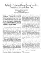
37%
11%
17%
9%
26%
Pow er/Prop
Flight Control
Com unicacione s
Human/Ground
Miscellaneous
Fig. 3. Average sources of System Failures for U. S. Military UAV
Fig. 4. Vario Benzin Trainer Helicopter.
Fig. 5. Helicopter Components.
The motor is responsible for generating the movement of the rotors of the helicopter, see
Figure 6. The combustion motor is powered by gasoline and fuel injection for the operation
is done through a servo. This system has a controller that is responsible for maintaining the
Fig. 2. Unmanned Aerial Vehicle
At present there is no regulation about the use of UAVs. Considering the increase in their
application and operations, guidelines that define their use and classification have to be
implemented in order to regulate their use. This action aims to avoid endangering persons,
by defining flying areas and respecting the norms of aviation.
There is a source of information about reliability of the UAVs and it is in the military field
(Office of the Secretary of Defense USA, 2003). Although there is currently some research on
UAVSs in FD (Bateman et al., 2008)(Qi et al., 2007)(Drozexki aet al., 2005). This aims to make
efforts in the FD of UAVs, which are complex systems and therefore vulnerable to failures
without a posterior diagnosis.
According to data taken from The Office of the Secretary of Defense USA, 2003, reported
failures in the UVS can be classified by deficiencies in: Power / Propulsion, Flight Control,
Communication, Ground Control / Human Factors, Miscellaneous (Other), see Figure 3.
As shown in the figure 3, the highest number of failures given in UAVs is in the field of
Power/Propulsion, followed by the flight control area. The FD algorithm presented in this
chapter has been focused on this study in order to reduce the failure rate to the minimum.
5.1 Description of the UAV Used
A Vario Benzin Trainer model shown in figure 4 has been designed to test the FD algorithm,
which has been used as a tool for a large number of applications in research on Automatic
control at Cybernetics and Robotics group of the Universidad Politécnica de Madrid
(Barrientos et al., 2009).
The helicopter is made up of three fundamental systems: the engine, the main rotor (plate)
and the tail, see figure 5. If one of any these three systems fail, the mission has to be aborted
immediately since the aircraft will definitely crash.
ModellingandFaultDiagnosisbymeansofPetriNets.UnmannedAerialVehicleApplication 365
37%
11%
17%
9%
26%
Pow er/Prop
Flight Control
Com unicacione s
Human/Ground
Miscellaneous
Fig. 3. Average sources of System Failures for U. S. Military UAV
Fig. 4. Vario Benzin Trainer Helicopter.
Fig. 5. Helicopter Components.
The motor is responsible for generating the movement of the rotors of the helicopter, see
Figure 6. The combustion motor is powered by gasoline and fuel injection for the operation
is done through a servo. This system has a controller that is responsible for maintaining the
Fig. 2. Unmanned Aerial Vehicle
At present there is no regulation about the use of UAVs. Considering the increase in their
application and operations, guidelines that define their use and classification have to be
implemented in order to regulate their use. This action aims to avoid endangering persons,
by defining flying areas and respecting the norms of aviation.
There is a source of information about reliability of the UAVs and it is in the military field
(Office of the Secretary of Defense USA, 2003). Although there is currently some research on
UAVSs in FD (Bateman et al., 2008)(Qi et al., 2007)(Drozexki aet al., 2005). This aims to make
efforts in the FD of UAVs, which are complex systems and therefore vulnerable to failures
without a posterior diagnosis.
According to data taken from The Office of the Secretary of Defense USA, 2003, reported
failures in the UVS can be classified by deficiencies in: Power / Propulsion, Flight Control,
Communication, Ground Control / Human Factors, Miscellaneous (Other), see Figure 3.
As shown in the figure 3, the highest number of failures given in UAVs is in the field of
Power/Propulsion, followed by the flight control area. The FD algorithm presented in this
chapter has been focused on this study in order to reduce the failure rate to the minimum.
5.1 Description of the UAV Used
A Vario Benzin Trainer model shown in figure 4 has been designed to test the FD algorithm,
which has been used as a tool for a large number of applications in research on Automatic
control at Cybernetics and Robotics group of the Universidad Politécnica de Madrid
(Barrientos et al., 2009).
The helicopter is made up of three fundamental systems: the engine, the main rotor (plate)
and the tail, see figure 5. If one of any these three systems fail, the mission has to be aborted
immediately since the aircraft will definitely crash.
PetriNets:Applications366
Fig. 8. Tail Rotor System.
5.2 Application of the Fault Diagnosis Algorithm.
After analyzing the importance of the three systems that make up the helicopter and finding
a simple way to implement the FD tool, next step in based on the implementation of the
algorithm to the helicopter.
Some assumptions must be done during the development of the FD algorithm:
The helicopter has to be started manually.
No failure on the controller happens.
No failure on the power supply.
The algorithm starts with the implementation of the methodology in each subsystem
individually and after that, all of them are integrated into the diagnoser.
5.2.1 Classification of Subsystems in Helicopter.
The helicopter can be classified into three subsystems
321
HHHH
, see Figure 9, the
motor subsystem, main rotor subsystem and tail rotor subsystem.
5.2.2 Construction of the PN Model for each of the Components of the Subsystem.
The subsystem motor is made up of controllers, servos, fuel storage tank and sensors.
The measure variables are: The level of fuel in the tank (L), the motor temperature (T) and
the motor revolutions per minute (RPM). The faults to diagnose are: Fault Warming Motor
(FWM), that is the maximum temperature allowed in the motor for the helicopter to fly.
Lack of gasoline in the fuel tank (FLF). The level of fuel in the tank should not move below a
minimum threshold. Stuck failure in Servo (FSS1). It could appear when the controller gives
a command for opening or closing the passage of the fuel servo, and does not respond
accordingly, i.e. the RPM falls below a minimum threshold, it may be due to a blockage of
the servo. Faults can occur in any place of the devices.
rotor speed constant during the flight . It is then important to monitor the level of fuel in
order to react in time. It is also vital to check that the servo is working properly.
Fig. 6. Motor of the Helicopter Varior Benzin Trainer.
The main rotor system, see Figure 7, is controlled by four servos that are in charge of
driving the blades so as to direct the helicopter according such as desired trajectory. The
main rotor and its respective servos are connected to the motor through a mechanical
transmission. Although there is a redundancy in the use of four servos for controlling the
main swash plate (only three servos are required), in case of any failure in any of them, the
pilot will probably lose the control. Therefore, it is important to monitor these servos.
The Tail Rotor is made up of two small blades and a servo that controls their tilt angle. The
Yaw angle of the helicopter can be modified by changing this tilt angle in the tail rotor
blades. If the tail rotor servo is damaged, the aircraft will lose the control.
Fig. 7. Main Rotor System.
The Helicopter relies on additional devices that are also relevant in order to maintain flight
plan, such as: The voltage of the Power Supply, sensors (IMU, gyroscopes, GPS, etc.),
controllers, communications, ground control station and so on. The payload can also be
considered as a relevant part of the aircraft.
ModellingandFaultDiagnosisbymeansofPetriNets.UnmannedAerialVehicleApplication 367
Fig. 8. Tail Rotor System.
5.2 Application of the Fault Diagnosis Algorithm.
After analyzing the importance of the three systems that make up the helicopter and finding
a simple way to implement the FD tool, next step in based on the implementation of the
algorithm to the helicopter.
Some assumptions must be done during the development of the FD algorithm:
The helicopter has to be started manually.
No failure on the controller happens.
No failure on the power supply.
The algorithm starts with the implementation of the methodology in each subsystem
individually and after that, all of them are integrated into the diagnoser.
5.2.1 Classification of Subsystems in Helicopter.
The helicopter can be classified into three subsystems
321
HHHH , see Figure 9, the
motor subsystem, main rotor subsystem and tail rotor subsystem.
5.2.2 Construction of the PN Model for each of the Components of the Subsystem.
The subsystem motor is made up of controllers, servos, fuel storage tank and sensors.
The measure variables are: The level of fuel in the tank (L), the motor temperature (T) and
the motor revolutions per minute (RPM). The faults to diagnose are: Fault Warming Motor
(FWM), that is the maximum temperature allowed in the motor for the helicopter to fly.
Lack of gasoline in the fuel tank (FLF). The level of fuel in the tank should not move below a
minimum threshold. Stuck failure in Servo (FSS1). It could appear when the controller gives
a command for opening or closing the passage of the fuel servo, and does not respond
accordingly, i.e. the RPM falls below a minimum threshold, it may be due to a blockage of
the servo. Faults can occur in any place of the devices.
rotor speed constant during the flight . It is then important to monitor the level of fuel in
order to react in time. It is also vital to check that the servo is working properly.
Fig. 6. Motor of the Helicopter Varior Benzin Trainer.
The main rotor system, see Figure 7, is controlled by four servos that are in charge of
driving the blades so as to direct the helicopter according such as desired trajectory. The
main rotor and its respective servos are connected to the motor through a mechanical
transmission. Although there is a redundancy in the use of four servos for controlling the
main swash plate (only three servos are required), in case of any failure in any of them, the
pilot will probably lose the control. Therefore, it is important to monitor these servos.
The Tail Rotor is made up of two small blades and a servo that controls their tilt angle. The
Yaw angle of the helicopter can be modified by changing this tilt angle in the tail rotor
blades. If the tail rotor servo is damaged, the aircraft will lose the control.
Fig. 7. Main Rotor System.
The Helicopter relies on additional devices that are also relevant in order to maintain flight
plan, such as: The voltage of the Power Supply, sensors (IMU, gyroscopes, GPS, etc.),
controllers, communications, ground control station and so on. The payload can also be
considered as a relevant part of the aircraft.
PetriNets:Applications368
diagnose in this subsystem is the servo stuck fail (FSS2), which is perceived when the
helicopter should go to an expected position and the sensors showed wrong reaction.
Fig. 11. Components PN Model of the Main Rotor Subsystems
The Tail Rotor subsystem consists of the servo which controls the pitch angle of the tail
blades, the transmission system to the blades of the tail rotor and the controller, see Figure
12. The abstract model of the controller is defined by an idle state (C5). When it receives the
turning forward to a new reference, a new pitch angle in the tail blades are required (AS5)
and them it moves to C6. The tail rotor servo is defined by an idle state (SNA3) and the
order of the controller (AS5, AS6) changes it to SRA3 state. The failure to diagnose in this
subsystem is the fault of servo stuck (FSS3).
Fig. 12. Components PN Model of the Tail Rotor Subsystem.
5.2.2 Building of the General PN Model.
The general PN model integrates the models of each individual components, it allows seeing
in a single PN model the normal and failure operation of each subsystem. In this new model
the places and transitions failure remain as in individual models, but the union of the
normal places has been performed. In the general PN model of the motor subsystem two
new places have been considered (P1, P2). The normal places of the controller C1 and the
current action of the servo SNA1 are synchronously integrated in P1. By other hand, P2
integrates the places of the controller C2 and required action of servo SRA2, see Figure 13.
In the general PN model of the main rotor subsystem, two new places are added (P3, P4). In
P3 the normal operation of the controller C3 and current position of all servos (SNA2) are
integrated, and P4 integrates the normal operation of the controller C4 and position of all
servos expected (SRA2) , as figure 14 shows.
Fig. 9. Classification of Subsystems of the helicopter.
Figure 10 defines the PN model of the servo and controller. The integration of normal
functioning and the three kind of failures listed above have been taken into account in each
PN. The fault transitions are unobservable (Tuo) and are represented by bars and shaded
circles. The PN model of the controller is an abstraction of its operation. Considering C1 as a
idle state of the controller where it is waiting for a command of the pilot through the servo
(AS1), when it happens, the controller changes to another state (C2). When the controller is
located at C2 and receives a new command AS2 it returns to place C1. In the same way as
the controller, the PN model of servo takes into account the normal and the failure behavior.
Starting from the idle place SNA1, when an order of the controller is received (AS1), it has to
move to required action place (SRA1).
Fig. 10. Components PN Model of the Motor Subsystem
The Main Rotor subsystem is made of four servos and a controller (in autonomous
systems) that sends information to them in order to control the attitude of the plate and
therefore the attitude of the helicopter that is the way to control the velocity, see Figure 11.
The controller model moves from a state of an idle position (C3) to an expected position
(C4). A single model of servo PN has been defined, which represents the four servos that
control the plate. In addition to this, the model considers that when the servos are in a idle
position (SNA2) and a change is required (AS3) the position (SRA2) is reached. The fault to
Main Rotor Subsystem
Tail Rotor Subs
y
stem
Power
p
lant Subs
y
stem
ModellingandFaultDiagnosisbymeansofPetriNets.UnmannedAerialVehicleApplication 369
diagnose in this subsystem is the servo stuck fail (FSS2), which is perceived when the
helicopter should go to an expected position and the sensors showed wrong reaction.
Fig. 11. Components PN Model of the Main Rotor Subsystems
The Tail Rotor subsystem consists of the servo which controls the pitch angle of the tail
blades, the transmission system to the blades of the tail rotor and the controller, see Figure
12. The abstract model of the controller is defined by an idle state (C5). When it receives the
turning forward to a new reference, a new pitch angle in the tail blades are required (AS5)
and them it moves to C6. The tail rotor servo is defined by an idle state (SNA3) and the
order of the controller (AS5, AS6) changes it to SRA3 state. The failure to diagnose in this
subsystem is the fault of servo stuck (FSS3).
Fig. 12. Components PN Model of the Tail Rotor Subsystem.
5.2.2 Building of the General PN Model.
The general PN model integrates the models of each individual components, it allows seeing
in a single PN model the normal and failure operation of each subsystem. In this new model
the places and transitions failure remain as in individual models, but the union of the
normal places has been performed. In the general PN model of the motor subsystem two
new places have been considered (P1, P2). The normal places of the controller C1 and the
current action of the servo SNA1 are synchronously integrated in P1. By other hand, P2
integrates the places of the controller C2 and required action of servo SRA2, see Figure 13.
In the general PN model of the main rotor subsystem, two new places are added (P3, P4). In
P3 the normal operation of the controller C3 and current position of all servos (SNA2) are
integrated, and P4 integrates the normal operation of the controller C4 and position of all
servos expected (SRA2) , as figure 14 shows.
Fig. 9. Classification of Subsystems of the helicopter.
Figure 10 defines the PN model of the servo and controller. The integration of normal
functioning and the three kind of failures listed above have been taken into account in each
PN. The fault transitions are unobservable (Tuo) and are represented by bars and shaded
circles. The PN model of the controller is an abstraction of its operation. Considering C1 as a
idle state of the controller where it is waiting for a command of the pilot through the servo
(AS1), when it happens, the controller changes to another state (C2). When the controller is
located at C2 and receives a new command AS2 it returns to place C1. In the same way as
the controller, the PN model of servo takes into account the normal and the failure behavior.
Starting from the idle place SNA1, when an order of the controller is received (AS1), it has to
move to required action place (SRA1).
Fig. 10. Components PN Model of the Motor Subsystem
The Main Rotor subsystem is made of four servos and a controller (in autonomous
systems) that sends information to them in order to control the attitude of the plate and
therefore the attitude of the helicopter that is the way to control the velocity, see Figure 11.
The controller model moves from a state of an idle position (C3) to an expected position
(C4). A single model of servo PN has been defined, which represents the four servos that
control the plate. In addition to this, the model considers that when the servos are in a idle
position (SNA2) and a change is required (AS3) the position (SRA2) is reached. The fault to
Main Rotor Subsystem
Tail Rotor Subs
y
stem
Power
p
lant Subs
y
stem
PetriNets:Applications370
The following concepts have been considered in the fault diagnosis system. Fuel Level tank
(FLF), motor warming (FWM) and servo Fault (FSS1), as Table 1 shows. The measures from
the sensors are defined as follows: Tank Level L=0, if the tank level is below the threshold
and else L=1. This means that when the level L is equal to 0, the helicopter indicates a fault.
The nominal temperature T of the motor must be under a threshold, thus when T=0
indicates that the motor temperature is in the normal range of operation, and T=1 means an
overheated motor. The revolutions of the motor RPM are also evaluated by using a
threshold. Thus RPM=0 means that motor revolutions is over this value (normal behavior),
and if the RPM=1 means that the motor is not responding to controller orders and possibly
there is a fault of servo or FLF, i.e. fuel injection failure. Table 1 shows all the possible
combinations of the outputs from the sensors that define if the PN that represents the
system falls into a fault or not. As general model defines, the subsystem of the motor has
two places P1 and P2. In a normal operation of the motor, sensor readings should be at L=1, T=0
and RPM=0, therefore, if the system is in either P1 or P2 and the state of the sensor changes, a
fault have been detected, indicating that the fault is no longer an unobservable transition, and it is
moved a transition observable, defined by the corresponding sensors Outputs.
Applying the same concepts, the integrating sensor table for main rotor subsystem has been
defined, see Table 2. We assess the fault of the servos FSS2, which is represented by the
signals taken from the position sensors P and a time on the expected response t1. P=0 if the
position given by the sensors is normal (no difference greater than 5% of the expected
position), and P=1 if the difference exceeds this position. The time t1=0 if the response time
of the expected position is less than 5 ms. and t1=1 if the response time is above the
threshold of 5 ms. For places P3 and P4 readings measures should be P=0 and t1=0. If there
is an unexpected change in the readings taken, the PN indicates a fault of stuck of any of the
servos.
L
T
RPM
)0,0,1(1P )0,0,1(2P
0 0 0
F
L
F
N N
F
L
F
N N
0 0 1
F
L
F
N 1FSS
F
L
F
N 1FSS
0 1 0
F
L
F
FWM
N
F
L
F
FWM N
0 1 1
F
L
F
FWM
1FSS
F
L
F
FWM 1FSS
1 0 0
N N N N N N
1 0 1
N N 1FSS
N N 1FSS
1 1 0
N FWM
N N FWM N
1 1 1
N FWM
1FSS
N FWM 1FSS
Table 1. Integrating Sensor Table of the Motor Subsystem.
The integrating sensors table for Tail Rotor Subsystem is shown in Table 3. The fault to
diagnose is the servo stuck FSS3. It is evaluated by reading the yaw angle (Yaw) and the
expected response time t2. The yaw angle y=0 if and angle of the expected movement of the
helicopter is less than 5 degrees and y=1 if the yaw angle exceeds the threshold. Time t2=0 if
the response time of the expected position is less than 5 ms. and t2=1 if the response time is
above the threshold of 5 ms. In places P5 and P6 for the normal operation the readings must
be y=0 and t2=0. When the PN reach from any place a variation of normal measures, the PN
indicates a fault of tail rotor servo stuck.
Fig. 13. General PN Model of Motor Subsystem.
Fig. 14. General PN Model of the Main Rotor Subsystem
There are two new places in the general PN model of the tail rotor subsystem, (P5, P6). In
P5 the normal operation of the controller C5 and the current position of the servo (SNA3)
are integrated. P6 integrates the normal operation of the controller C6 and the servo
required position (SRA3), as Figure 15 shows.
Fig. 15. General PN Model of the Tail Rotor Subsystem.
5.2.3 Building of the Sensors Integration Table.
The subsequent step in the implementation of the FD algorithm, is to refine the PN general
model, due to the fault transition (Tuo) have to be replaced with observables transitions
(To). This process was made based on measures variables (sensors) with which system relies
on. For this reason, the sensors integration table has to be define, it summarizes the possible
outputs of the sensors. When this subsystem is in anywhere place of the normal operation,
sensors can provide with different measures to those expected, indicating the presence of
failure. These sensorial readings replace the failure transition and, in this way, the general
PN model can be refined. The sensor integration table is developed for each subsystem.
ModellingandFaultDiagnosisbymeansofPetriNets.UnmannedAerialVehicleApplication 371
The following concepts have been considered in the fault diagnosis system. Fuel Level tank
(FLF), motor warming (FWM) and servo Fault (FSS1), as Table 1 shows. The measures from
the sensors are defined as follows: Tank Level L=0, if the tank level is below the threshold
and else L=1. This means that when the level L is equal to 0, the helicopter indicates a fault.
The nominal temperature T of the motor must be under a threshold, thus when T=0
indicates that the motor temperature is in the normal range of operation, and T=1 means an
overheated motor. The revolutions of the motor RPM are also evaluated by using a
threshold. Thus RPM=0 means that motor revolutions is over this value (normal behavior),
and if the RPM=1 means that the motor is not responding to controller orders and possibly
there is a fault of servo or FLF, i.e. fuel injection failure. Table 1 shows all the possible
combinations of the outputs from the sensors that define if the PN that represents the
system falls into a fault or not. As general model defines, the subsystem of the motor has
two places P1 and P2. In a normal operation of the motor, sensor readings should be at L=1, T=0
and RPM=0, therefore, if the system is in either P1 or P2 and the state of the sensor changes, a
fault have been detected, indicating that the fault is no longer an unobservable transition, and it is
moved a transition observable, defined by the corresponding sensors Outputs.
Applying the same concepts, the integrating sensor table for main rotor subsystem has been
defined, see Table 2. We assess the fault of the servos FSS2, which is represented by the
signals taken from the position sensors P and a time on the expected response t1. P=0 if the
position given by the sensors is normal (no difference greater than 5% of the expected
position), and P=1 if the difference exceeds this position. The time t1=0 if the response time
of the expected position is less than 5 ms. and t1=1 if the response time is above the
threshold of 5 ms. For places P3 and P4 readings measures should be P=0 and t1=0. If there
is an unexpected change in the readings taken, the PN indicates a fault of stuck of any of the
servos.
L
T
RPM
)0,0,1(1P )0,0,1(2P
0 0 0
F
L
F
N N
F
L
F
N N
0 0 1
F
L
F
N 1FSS
F
L
F
N 1FSS
0 1 0
F
L
F
FWM
N
F
L
F
FWM N
0 1 1
F
L
F
FWM
1FSS
F
L
F
FWM 1FSS
1 0 0
N N N N N N
1 0 1
N N 1FSS
N N 1FSS
1 1 0
N FWM
N N FWM N
1 1 1
N FWM
1FSS
N FWM 1FSS
Table 1. Integrating Sensor Table of the Motor Subsystem.
The integrating sensors table for Tail Rotor Subsystem is shown in Table 3. The fault to
diagnose is the servo stuck FSS3. It is evaluated by reading the yaw angle (Yaw) and the
expected response time t2. The yaw angle y=0 if and angle of the expected movement of the
helicopter is less than 5 degrees and y=1 if the yaw angle exceeds the threshold. Time t2=0 if
the response time of the expected position is less than 5 ms. and t2=1 if the response time is
above the threshold of 5 ms. In places P5 and P6 for the normal operation the readings must
be y=0 and t2=0. When the PN reach from any place a variation of normal measures, the PN
indicates a fault of tail rotor servo stuck.
Fig. 13. General PN Model of Motor Subsystem.
Fig. 14. General PN Model of the Main Rotor Subsystem
There are two new places in the general PN model of the tail rotor subsystem, (P5, P6). In
P5 the normal operation of the controller C5 and the current position of the servo (SNA3)
are integrated. P6 integrates the normal operation of the controller C6 and the servo
required position (SRA3), as Figure 15 shows.
Fig. 15. General PN Model of the Tail Rotor Subsystem.
5.2.3 Building of the Sensors Integration Table.
The subsequent step in the implementation of the FD algorithm, is to refine the PN general
model, due to the fault transition (Tuo) have to be replaced with observables transitions
(To). This process was made based on measures variables (sensors) with which system relies
on. For this reason, the sensors integration table has to be define, it summarizes the possible
outputs of the sensors. When this subsystem is in anywhere place of the normal operation,
sensors can provide with different measures to those expected, indicating the presence of
failure. These sensorial readings replace the failure transition and, in this way, the general
PN model can be refined. The sensor integration table is developed for each subsystem.
PetriNets:Applications372
Fig. 17. Refined PN Model of the Main Rotor Subsystem
Fig. 18. Refined PN Model of the Tail Rotor Subsystem-
5.2.5 Building of the Diagnoser
The PN that represents the diagnoser is mainly composed of three branches, corresponding
to each subsystem: motor branch, main and tail rotor branch, see Figure 19. the final goal of
algorithm is integrated in one single PN the FD helicopter. The construction of each branch
is based on the functions of Fault Expansion EF and Label Assigned AL. In PN diagnoser
there are not sink places that can block the operation of the PN. The diagnoser makes an
online assessment of whole system and serves as the supervisor, indicating where any of the
branches fell into failure. If a branch falls on failure, the other branches continue assessing
the system, although due to vulnerability of the helicopter must be taken to a place safe or
landing for their repair.
Diagnoser has a normal place of start START and start transition START, the transition
START is activated by the pilot of the ground control station to start the PN diagnoser and
move a token for each of the branches of the helicopter subsystems. Likewise, the PN
diagnoser has a transition end END, which allows the pilot to finish the diagnoser. The
diagnoser is showed in the display of the ground control station. As in any system may
occur intermittent fault, in the diagnoser have been added recovery transitions necessary to
that if a fault is returned to its normal place can be observed by the pilot and take the
necessary precautions.
The diagnoser is a tool that is added to display of the ground control station and is
monitored by the pilot. Although the diagnoser has direct relation with the flight control,
where it receives signals to assess faults, does not send any signal to the flight control, which
could alter the functioning of the planned mission.
P
1t
)0,0(,3P )0,0(,4P
0 0
N N
0 1
2FSS 2FSS
1 0
2FSS 2FSS
1 1
2FSS 2FSS
Table 2. Integration Sensors Table of the Main Rotor Subsystem.
y
2t
)0,0(,5P )0,0(,5P
0 0
N N
0 1
3FSS 3FSS
1 0
3FSS 3FSS
1 1
3FSS 3FSS
Table 3. Integration Sensor Table of the Subsystem tail rotor.
5.2.4 Construction of the Refined PN Model.
The general PN model is composed of observable To and unobservable Tuo transitions,
equivalent to faults transitions. These transitions unobservable have to be replaced by
observable transitions; this is known as a refinement of the general model. After building
the integration sensors table for each subsystem, is simply replace the transitions
unobserved by the measure reading that indicates that PN falls within fault corresponding.
For the motor subsystem, the transition of fault level fuel FLF have been replaced with
reading the fuel level L. transition fault motor warm FWM is replaced by a reading of
temperature T and the transition of fault servo stuck FSS1 have been replaced with reading
the RPM and fuel level L, see Figure 16.
Fig. 16. Refined PN Model of the Motor Subsystem
The refined PN model of main rotor subsystem is shown in Figure 17. The transition fault
servos stuck FSS2 has been replaced by the reading position P and the response time t1. The
refined PN model of tail rotor subsystem is shown in Figure 18. The transition fault servo
stuck of the tail rotor FSS3 has been replaced by the readings of the yaw angle and response
time t2.
ModellingandFaultDiagnosisbymeansofPetriNets.UnmannedAerialVehicleApplication 373
Fig. 17. Refined PN Model of the Main Rotor Subsystem
Fig. 18. Refined PN Model of the Tail Rotor Subsystem-
5.2.5 Building of the Diagnoser
The PN that represents the diagnoser is mainly composed of three branches, corresponding
to each subsystem: motor branch, main and tail rotor branch, see Figure 19. the final goal of
algorithm is integrated in one single PN the FD helicopter. The construction of each branch
is based on the functions of Fault Expansion EF and Label Assigned AL. In PN diagnoser
there are not sink places that can block the operation of the PN. The diagnoser makes an
online assessment of whole system and serves as the supervisor, indicating where any of the
branches fell into failure. If a branch falls on failure, the other branches continue assessing
the system, although due to vulnerability of the helicopter must be taken to a place safe or
landing for their repair.
Diagnoser has a normal place of start START and start transition START, the transition
START is activated by the pilot of the ground control station to start the PN diagnoser and
move a token for each of the branches of the helicopter subsystems. Likewise, the PN
diagnoser has a transition end END, which allows the pilot to finish the diagnoser. The
diagnoser is showed in the display of the ground control station. As in any system may
occur intermittent fault, in the diagnoser have been added recovery transitions necessary to
that if a fault is returned to its normal place can be observed by the pilot and take the
necessary precautions.
The diagnoser is a tool that is added to display of the ground control station and is
monitored by the pilot. Although the diagnoser has direct relation with the flight control,
where it receives signals to assess faults, does not send any signal to the flight control, which
could alter the functioning of the planned mission.
P
1t
)0,0(,3P )0,0(,4P
0 0
N N
0 1
2FSS 2FSS
1 0
2FSS 2FSS
1 1
2FSS 2FSS
Table 2. Integration Sensors Table of the Main Rotor Subsystem.
y
2t
)0,0(,5P )0,0(,5P
0 0
N N
0 1
3FSS 3FSS
1 0
3FSS 3FSS
1 1
3FSS 3FSS
Table 3. Integration Sensor Table of the Subsystem tail rotor.
5.2.4 Construction of the Refined PN Model.
The general PN model is composed of observable To and unobservable Tuo transitions,
equivalent to faults transitions. These transitions unobservable have to be replaced by
observable transitions; this is known as a refinement of the general model. After building
the integration sensors table for each subsystem, is simply replace the transitions
unobserved by the measure reading that indicates that PN falls within fault corresponding.
For the motor subsystem, the transition of fault level fuel FLF have been replaced with
reading the fuel level L. transition fault motor warm FWM is replaced by a reading of
temperature T and the transition of fault servo stuck FSS1 have been replaced with reading
the RPM and fuel level L, see Figure 16.
Fig. 16. Refined PN Model of the Motor Subsystem
The refined PN model of main rotor subsystem is shown in Figure 17. The transition fault
servos stuck FSS2 has been replaced by the reading position P and the response time t1. The
refined PN model of tail rotor subsystem is shown in Figure 18. The transition fault servo
stuck of the tail rotor FSS3 has been replaced by the readings of the yaw angle and response
time t2.
PetriNets:Applications374
6. Conclusion
This chapter has addressed the issue of fault diagnosis of hybrid systems using PN. An
algorithm for construction of the model and a Diagnoser has been presented. The process
has been classified into subsystems, which assesses the failure of independent way.
The proposed methodology turns out to be easy to implement and its construction
incorporates devices that handle both continuous and discrete variables. They main
advantages are the reduction of the combinational explosion, a systematic construction, the
ability to be implemented in complex processes and the flexibility to make changes or add
additional devices to be diagnosed.
As a demonstration, an application of a real hybrid system has been presented. The
implementation on a radio control helicopter, which is a quite vulnerable and requires a
robust fault diagnosis method.
7. References
Barrientos, A., Gutiérrez, P. & Colorado, J. (2009). Advanced UAV Trajectory Generation:
Planning and Guidance, In: Recent Advances in Signal Processing, IN-TECH, pp. 56-
82, ISBN 978-953-7619-41-1, Austria.
Bateman, F.; Noura, H. & Ouladsine, M. (2007). Actuators Fault Diagnosis and Tolerant
Control for an Unmanned Aerial Vehicle, 16th IEEE International Conference on
Control Applications Part of IEEE Multi-conference on Systems and Control Singapore,
October 2007.
Bateman, F.; Noura, H. & Ouladsine, M. (2008). Active Fault Detection and Isolation
Strategy for an Unmanned Aerial Vehicle with Redundant Flight Control Surfaces,
16th Mediterranean Conference on Control and Automation Congress Centre, Ajaccio,
France, June 2008.
Bonfe, M.; Castaldi, P.; Geri, W. & Simani, S.(2006). Fault detection and isolation for on-
board sensors of a general aviation aircraft, International Journal Of Adaptive Control
And Signal Processing Int. J. Adapt. Control Signal Process, May 2006.
Cassandras, C. (2002). From Discrete Event to Hybrid Systems, Boston University, IEEE, 2002.
Chung, S. & Jeng, M. (2003). Failure Diagnosis: A case Study on Modeling and Analysis by
Petri Nets, IEEE, 2003.
Cork, L.; Walker, R. & Dunn, S. (2005). Fault Detection, Identification and Accommodation
Techniques for Unmanned Airborne Vehicle, Australian International Aerospace
Congress, Melbourne, march 2005.
David, R. & Alla, H. (1992). Petri Nets & Grafcet: Tools for modelling discrete event, Prentice
Hall, Great Britain, 1992.
Drozeski, G., Saha, B. & Vachtsevanos, G. (2005). A Fault Detection and Reconfigurable
Control Architecture for Unmanned Aerial Vehicles, Aerospace Conference 2005
IEEE, March 2005.
Elgersma, M. & GlavaSki, S. (2001). Reconfigurable Control for Active Management of
Aircraft System Failures, Proceedings of the American Control Conference Arlington,
VA, June 2001.
Fourlas, G. Kyriakopoulos, K. & Krikelis, N. (2005). Fault Diagnosis of Hybrid Systems,
International Symposium on the Intelligent Control, IEEE, Limassol Cyprus, 2005.
Fig. 19. Helicopter Diagnoser
ModellingandFaultDiagnosisbymeansofPetriNets.UnmannedAerialVehicleApplication 375
6. Conclusion
This chapter has addressed the issue of fault diagnosis of hybrid systems using PN. An
algorithm for construction of the model and a Diagnoser has been presented. The process
has been classified into subsystems, which assesses the failure of independent way.
The proposed methodology turns out to be easy to implement and its construction
incorporates devices that handle both continuous and discrete variables. They main
advantages are the reduction of the combinational explosion, a systematic construction, the
ability to be implemented in complex processes and the flexibility to make changes or add
additional devices to be diagnosed.
As a demonstration, an application of a real hybrid system has been presented. The
implementation on a radio control helicopter, which is a quite vulnerable and requires a
robust fault diagnosis method.
7. References
Barrientos, A., Gutiérrez, P. & Colorado, J. (2009). Advanced UAV Trajectory Generation:
Planning and Guidance, In: Recent Advances in Signal Processing, IN-TECH, pp. 56-
82, ISBN 978-953-7619-41-1, Austria.
Bateman, F.; Noura, H. & Ouladsine, M. (2007). Actuators Fault Diagnosis and Tolerant
Control for an Unmanned Aerial Vehicle, 16th IEEE International Conference on
Control Applications Part of IEEE Multi-conference on Systems and Control Singapore,
October 2007.
Bateman, F.; Noura, H. & Ouladsine, M. (2008). Active Fault Detection and Isolation
Strategy for an Unmanned Aerial Vehicle with Redundant Flight Control Surfaces,
16th Mediterranean Conference on Control and Automation Congress Centre, Ajaccio,
France, June 2008.
Bonfe, M.; Castaldi, P.; Geri, W. & Simani, S.(2006). Fault detection and isolation for on-
board sensors of a general aviation aircraft, International Journal Of Adaptive Control
And Signal Processing Int. J. Adapt. Control Signal Process, May 2006.
Cassandras, C. (2002). From Discrete Event to Hybrid Systems, Boston University, IEEE, 2002.
Chung, S. & Jeng, M. (2003). Failure Diagnosis: A case Study on Modeling and Analysis by
Petri Nets, IEEE, 2003.
Cork, L.; Walker, R. & Dunn, S. (2005). Fault Detection, Identification and Accommodation
Techniques for Unmanned Airborne Vehicle, Australian International Aerospace
Congress, Melbourne, march 2005.
David, R. & Alla, H. (1992). Petri Nets & Grafcet: Tools for modelling discrete event, Prentice
Hall, Great Britain, 1992.
Drozeski, G., Saha, B. & Vachtsevanos, G. (2005). A Fault Detection and Reconfigurable
Control Architecture for Unmanned Aerial Vehicles, Aerospace Conference 2005
IEEE, March 2005.
Elgersma, M. & GlavaSki, S. (2001). Reconfigurable Control for Active Management of
Aircraft System Failures, Proceedings of the American Control Conference Arlington,
VA, June 2001.
Fourlas, G. Kyriakopoulos, K. & Krikelis, N. (2005). Fault Diagnosis of Hybrid Systems,
International Symposium on the Intelligent Control, IEEE, Limassol Cyprus, 2005.
Fig. 19. Helicopter Diagnoser
PetriNets:Applications376
Trigos, M. & Garcia, E. (2008-B). Faults Diagnosis and Modelling of the Liquid Packaging
Process. A Research Based on Petri Nets, Proceeding from the 10th International
Conference of Robotics & Automation IEEE, December 2008, Hanoi – Vietnam.
Ushio, T.; Onishi, I. & Okuda, K. (1998). Fault Detection Based on Petri Net models with
Faulty Behaviors , IEEE, 1998
Venkatasubramanian, V.; Raghunathan, R.; Kemen, Y. and Surya, K. (2003). A review of
process fault detection and diagnosis: Quantitative, Qualitative and History Process
methods, Computer and Chemical Engineering, no. 27, pp. 293-346.
Zhang, X.; Liu, Y.; Rysdyk, R.; Kwan, C. & Xu, R. (2006). An Intelligent Hierarchical
Approach to Actuator Fault Diagnosis and Accommodation, Aerospace Conference,
2006 IEEE.
Zhao, F.; Koutsoukos, V.; Haussecker, H.; Reich, J. & Cheung, P. (2005). Monitoring and
Fault Diagnosis of Hybrid Systems, IEEE Trans. Actions on Systems, Man, and
Cybernetics- Part B: Cybertnetics, Vol. 35, no. 6, December 2005.
Genc, S. & Lafortune, S. (2006). Distributed Diagnosis of Places-boundered Petri Nets,
Department of Electrical Engineering and Computer Science, University of Michigan,
USA, 2006.
Giua, A. & Seatzu, C. (2005). Fault detection for discrete event systems using Petri Nets with
unobservable transitions , 44th IEEE Conference on Decision and Control, Seville,
Spain, December 2005.
GlavaSki, S. & Elgersma, M. (2001). Active Aircraft Fault Detection and Isolation,
AUTOTESTCON Proceedings 2001 IEEE Systems Readiness Technology Conference,
2001.
Hayhurst, K.; Maddalon, J. & Miner, P. (2006). Unmanned Aircraft Hazards And Their
Implications For Regulation, 25th Digital Avionics Systems Conference, NASA
Langley Research Center, Hampton, Inc., Eastsound, WA, October 2006.
Henzinger, T. A. (1996) The Theory of Hybrid Systems, Proccedings of the 11th Annual IEEE
Symposium on Logic in Computer Science, pp.278-292, Lics, 1996.
Heredia, G.; Ollero, A.; Mahtani, R.; Béjar, M.; Remuß, V. & Musial, M. (2005). Detection of
Sensor Faults in Autonomous Helicopters, Proc. of the 2005 IEEE International
Conference on Robotics and Automation (ICRA 2005), Barcelona, Spain. April 2005.
Krogh, B. H. (2002). Recent Advances in Discrete Analysis and Control of Hybrid Systems,
Carnegie Mellon University, Pittsburgh, USA, IEEE, 2002.
Mancini, A.; Caponetti, F.; Monteri`u, A.; Frontoni, E.; Zingaretti, P & Longhi, S. (2007) Safe
flying for an UAV Helicopter, Mediterranean conference on control and automation
2007, Athens – Greece, July 2007
Murata, T. (1989). Petri Nets: Properties, Analysis and Applications, Proc. IEEE, Apr. 1989,
Vol. 77, no. 4, pp. 541-580.
Narasimhan, S.; Zhao, F.; Biswas, G. & Hung, E. (2000). Fault Isolation In Hibrid Systems
Combining Model Based Diagnosis and Signal Proccesing, Vanderbilt University,
IFAC 2000.
Office of the Secretary of Defense USA. (2003), Unmanned Aerial Vehicle Reliability Study,
United States of America, February 2003.
Qi, J., Jiang, Z.; Zhao, X. & Han, J. (2007). Fault Detection Design for RUAV with an
Adaptive Threshold Neural-Network Scheme, 2007 IEEE International Conference on
Control and Automation, Guangzhou, CHINA, May 2007.
Ramírez, A.; Ruíz, E.; Rivera, I. & López, E. (2007). Online Fault Diagnosis of Discrete Event
Systems. A Petri Net Based Approach, IEEE Trans. On Autom. Science and
Engineering, Vol. 4, no. 1, January 2007.
Samar, S.; Gorinevsky, D. & Boyd, S. (2006). Embedded Estimation of Fault Parameters in an
Unmanned Aerial Vehicle, Proceedings of the 2006 IEEE International Conference on
Control Applications Munich, Germany,, October 4-6, 2006.
Sampath, M., Sengupta, R.; Lafortune, S.; Sinnamohidee, K. & D. Teneketzis, (1995).
Diagnosability of Discrete Event Systems, IEEE Trans Autom. Contr, Vol. 40, no 9,
pp. 1555-1575, 1995.
Silva, M. (1985). Las Redes de Petri: en la Automática y la Informática, Editorial AC, Madrid -
España, 1985.
Trigos, M. & García, E. (2008-A). Diagnóstico De Fallos De Sistemas De Eventos Discretos
Basado En Redes De Petri, 5 Conferencia Internacional de Ingenierías Eléctrica FIE-08,
Julio 2008, Santiago de Cuba – Cuba.
ModellingandFaultDiagnosisbymeansofPetriNets.UnmannedAerialVehicleApplication 377
Trigos, M. & Garcia, E. (2008-B). Faults Diagnosis and Modelling of the Liquid Packaging
Process. A Research Based on Petri Nets, Proceeding from the 10th International
Conference of Robotics & Automation IEEE, December 2008, Hanoi – Vietnam.
Ushio, T.; Onishi, I. & Okuda, K. (1998). Fault Detection Based on Petri Net models with
Faulty Behaviors , IEEE, 1998
Venkatasubramanian, V.; Raghunathan, R.; Kemen, Y. and Surya, K. (2003). A review of
process fault detection and diagnosis: Quantitative, Qualitative and History Process
methods, Computer and Chemical Engineering, no. 27, pp. 293-346.
Zhang, X.; Liu, Y.; Rysdyk, R.; Kwan, C. & Xu, R. (2006). An Intelligent Hierarchical
Approach to Actuator Fault Diagnosis and Accommodation, Aerospace Conference,
2006 IEEE.
Zhao, F.; Koutsoukos, V.; Haussecker, H.; Reich, J. & Cheung, P. (2005). Monitoring and
Fault Diagnosis of Hybrid Systems, IEEE Trans. Actions on Systems, Man, and
Cybernetics- Part B: Cybertnetics, Vol. 35, no. 6, December 2005.
Genc, S. & Lafortune, S. (2006). Distributed Diagnosis of Places-boundered Petri Nets,
Department of Electrical Engineering and Computer Science, University of Michigan,
USA, 2006.
Giua, A. & Seatzu, C. (2005). Fault detection for discrete event systems using Petri Nets with
unobservable transitions , 44th IEEE Conference on Decision and Control, Seville,
Spain, December 2005.
GlavaSki, S. & Elgersma, M. (2001). Active Aircraft Fault Detection and Isolation,
AUTOTESTCON Proceedings 2001 IEEE Systems Readiness Technology Conference,
2001.
Hayhurst, K.; Maddalon, J. & Miner, P. (2006). Unmanned Aircraft Hazards And Their
Implications For Regulation, 25th Digital Avionics Systems Conference, NASA
Langley Research Center, Hampton, Inc., Eastsound, WA, October 2006.
Henzinger, T. A. (1996) The Theory of Hybrid Systems, Proccedings of the 11th Annual IEEE
Symposium on Logic in Computer Science, pp.278-292, Lics, 1996.
Heredia, G.; Ollero, A.; Mahtani, R.; Béjar, M.; Remuß, V. & Musial, M. (2005). Detection of
Sensor Faults in Autonomous Helicopters, Proc. of the 2005 IEEE International
Conference on Robotics and Automation (ICRA 2005), Barcelona, Spain. April 2005.
Krogh, B. H. (2002). Recent Advances in Discrete Analysis and Control of Hybrid Systems,
Carnegie Mellon University, Pittsburgh, USA, IEEE, 2002.
Mancini, A.; Caponetti, F.; Monteri`u, A.; Frontoni, E.; Zingaretti, P & Longhi, S. (2007) Safe
flying for an UAV Helicopter, Mediterranean conference on control and automation
2007, Athens – Greece, July 2007
Murata, T. (1989). Petri Nets: Properties, Analysis and Applications, Proc. IEEE, Apr. 1989,
Vol. 77, no. 4, pp. 541-580.
Narasimhan, S.; Zhao, F.; Biswas, G. & Hung, E. (2000). Fault Isolation In Hibrid Systems
Combining Model Based Diagnosis and Signal Proccesing, Vanderbilt University,
IFAC 2000.
Office of the Secretary of Defense USA. (2003), Unmanned Aerial Vehicle Reliability Study,
United States of America, February 2003.
Qi, J., Jiang, Z.; Zhao, X. & Han, J. (2007). Fault Detection Design for RUAV with an
Adaptive Threshold Neural-Network Scheme, 2007 IEEE International Conference on
Control and Automation, Guangzhou, CHINA, May 2007.
Ramírez, A.; Ruíz, E.; Rivera, I. & López, E. (2007). Online Fault Diagnosis of Discrete Event
Systems. A Petri Net Based Approach, IEEE Trans. On Autom. Science and
Engineering, Vol. 4, no. 1, January 2007.
Samar, S.; Gorinevsky, D. & Boyd, S. (2006). Embedded Estimation of Fault Parameters in an
Unmanned Aerial Vehicle, Proceedings of the 2006 IEEE International Conference on
Control Applications Munich, Germany,, October 4-6, 2006.
Sampath, M., Sengupta, R.; Lafortune, S.; Sinnamohidee, K. & D. Teneketzis, (1995).
Diagnosability of Discrete Event Systems, IEEE Trans Autom. Contr, Vol. 40, no 9,
pp. 1555-1575, 1995.
Silva, M. (1985). Las Redes de Petri: en la Automática y la Informática, Editorial AC, Madrid -
España, 1985.
Trigos, M. & García, E. (2008-A). Diagnóstico De Fallos De Sistemas De Eventos Discretos
Basado En Redes De Petri, 5 Conferencia Internacional de Ingenierías Eléctrica FIE-08,
Julio 2008, Santiago de Cuba – Cuba.