Optimizing and Testing WLANs: Proven Techniques for Maximum Performance pdf
Bạn đang xem bản rút gọn của tài liệu. Xem và tải ngay bản đầy đủ của tài liệu tại đây (7.89 MB, 268 trang )
Simpo PDF Merge and Split Unregistered Version -
Optimizing and Testing WLANs
Prelims-H7986.indd iPrelims-H7986.indd i 6/29/07 6:31:49 PM6/29/07 6:31:49 PM
Simpo PDF Merge and Split Unregistered Version -
This page intentionally left blank
Simpo PDF Merge and Split Unregistered Version -
Optimizing and Testing WLANs
Proven Techniques for Maximum Performance
By
Tom Alexander
AMSTERDAM • BOSTON • HEIDELBERG • LONDON
NEW YORK • OXFORD • PARIS • SAN DIEGO
SAN FRANCISCO • SINGAPORE • SYDNEY • TOKYO
Newnes is an imprint of Elsevier
Prelims-H7986.indd iiiPrelims-H7986.indd iii 6/29/07 6:31:51 PM6/29/07 6:31:51 PM
Simpo PDF Merge and Split Unregistered Version -
Newnes is an imprint of Elsevier
30 Corporate Drive, Suite 400, Burlington, MA 01803, USA
Linacre House, Jordan Hill, Oxford OX2 8DP, UK
Copyright © 2007, Elsevier Inc. All rights reserved.
No part of this publication may be reproduced, stored in a retrieval system, or
transmitted in any form or by any means, electronic, mechanical, photocopying,
recording, or otherwise, without the prior written permission of the publisher.
Permissions may be sought directly from Elsevier’s Science & Technology Rights
Department in Oxford, UK: phone: (ϩ44) 1865 843830, fax: (ϩ44) 1865 853333,
E-mail: You may also complete your request online via
the Elsevier homepage (), by selecting “Support & Contact” then
“Copyright and Permission” and then “Obtaining Permissions.”
Recognizing the importance of preserving what has been written,
Elsevier prints its books on acid-free paper whenever possible.
Library of Congress Cataloging-in-Publication Data
Alexander, Tom.
Testing 802.11 WLANs : techniques for maximum performance / By Tom Alexander.
p. cm.
Includes bibliographical references and index.
ISBN 978-0-7506-7986-2 (pbk. : alk. paper) 1. Wireless LANs–Security measures.
2. Local area networks (Computer networks)–Security measures. I. Title.
TK5105.78.A44 2007
004.6Ј8–dc22
2007017031
British Library Cataloguing-in-Publication Data
A catalogue record for this book is available from the British Library.
ISBN: 978-0-7506-7986-2
For information on all Newnes publications
visit our Web site at www.books.elsevier.com
07 08 09 10 10 9 8 7 6 5 4 3 2 1
Typeset by Charon Tec Ltd (A Macmillan Company), Chennai, India
www.charontec.com
Printed in the United States of America
Prelims-H7986.indd ivPrelims-H7986.indd iv 6/29/07 6:31:53 PM6/29/07 6:31:53 PM
Simpo PDF Merge and Split Unregistered Version -
Contents
Preface ix
Introduction xi
Chapter 1: IEEE 802.11 WLAN Systems 1
1.1 IEEE 802.11 Wireless Local Area Networks 1
1.2 WLAN Standards Today 3
1.3 Inside WLAN Devices 13
1.4 The RF Layer 19
Chapter 2: Metrology, Test Instruments, and Processes 27
2.1 Metrology: the Science of Measurement 27
2.2 The Nomenclature of Measurement 28
2.3 Measurement Quality Factors 31
2.4 The WLAN Engineer’s Toolbox 33
2.5 Test Setups and Test Processes 37
2.6 Repeatability 48
Chapter 3: WLAN Test Environments 55
3.1 Wired vs. Wireless .55
3.2 Types of Environments 56
3.3 Outdoor and Indoor OTA 59
3.4 Chambered OTA Testing 64
3.5 Conducted Test Setups 69
3.6 Repeatability 72
Chapter 4: Physical Layer Measurements 75
4.1 Types of PHY Layer Measurements 75
4.2 Transmitter Tests 77
4.3 Receiver Tests 90
4.4 Electromagnetic Compatibility Testing 94
4.5 System Performance Tests 99
4.6 Getting the DUT to Respond 105
v
Prelims-H7986.indd vPrelims-H7986.indd v 6/29/07 6:31:53 PM6/29/07 6:31:53 PM
Simpo PDF Merge and Split Unregistered Version -
Chapter 5: Protocol Testing 109
5.1 An Introduction to Protocol Testing 109
5.2 Conformance and Functional Testing 111
5.3 Interoperability Testing 117
5.4 Performance Testing 121
5.5 Standardized Benchmark Testing 133
Chapter 6: Application-Level Measurements 137
6.1 System-level Measurements 137
6.2 Application Traffi c Mixes 146
6.3 VoIP Testing 150
6.4 Video and Multimedia 158
6.5 Relevance and Repeatability 162
Chapter 7: WLAN Manufacturing Test 165
7.1 The WLAN Manufacturing Flow 165
7.2 Manufacturing Test Setups 171
7.3 Radio Calibration 175
7.4 Programming 176
7.5 Functional and System Testing 177
7.6 Failure Patterns 179
Chapter 8: Installation Test 181
8.1 Enterprise WLANs 181
8.2 Hot-spots 188
8.3 The Site Survey 190
8.4 Propagation Analysis and Prediction 196
8.5 Maintenance and Monitoring 202
Chapter 9: Testing MIMO Systems 207
9.1 What is MIMO? 207
9.2 The IEEE 802.11n PHY 219
9.3 A New PLCP/MAC Layer 225
9.4 The MIMO Testing Challenge 231
9.5 Channel Emulation 233
9.6 Testing 802.11n MIMO Devices 237
Appendix A: A Standards Guide 241
A.1 FCC Part 15 241
A.2 IEEE 802.11 242
Contents
vi
Prelims-H7986.indd viPrelims-H7986.indd vi 6/29/07 6:31:54 PM6/29/07 6:31:54 PM
Simpo PDF Merge and Split Unregistered Version -
A.3 Wi-Fi® Alliance 243
A.4 CTIA 243
A.5 IETF BMWG 244
Appendix B: Selected Bibliography 245
Index 249
Contents
vii
Prelims-H7986.indd viiPrelims-H7986.indd vii 6/29/07 6:31:54 PM6/29/07 6:31:54 PM
Simpo PDF Merge and Split Unregistered Version -
This page intentionally left blank
Simpo PDF Merge and Split Unregistered Version -
Preface
My purpose in writing this book is to present a comprehensive review of measurement
techniques used in the creation and optimization of IEEE 802.11 wireless LANs. Systematic
optimization of a system or process involves extensive measurements, to identify issues and
also to know when they have been fi xed. A thorough understanding of these measurements
and the underlying metrics will aid engineers in improving and extending their wireless LAN
equipment and installations.
The extremely rapid development of IEEE 802.11 wireless LANs has resulted in a general lack
of usable literature covering their test and measurement. As of this writing, wireless LANs are
still in their infancy, and methods of measuring and optimizing their performance are not well
understood. In fact, there is much confusion within the industry as to what should be measured,
let alone how. Equipment vendors try to remedy this by publishing articles, whitepapers and
application notes, but these are narrowly focused and usually promote the vendor’s point of
view. It is not unusual to fi nd representatives of leading vendors disagreeing on basic metrics and
approaches.
This book tries to present a broad overview of the entire fi eld, to provide the reader with a
context and foundation on which more detailed knowledge may be built. My goal is to
supply introduction and training material for designers and test engineers. A reader armed
with this knowledge should be able to sort out exactly what needs to be measured and how,
and what sort of equipment is best suited for the quantity being measured. Such information
also allows users, who may not be directly involved in equipment design, to understand the
methods that their equipment suppliers should have used to measure the numbers claimed on
datasheets.
I would like to take this opportunity to thank many colleagues who indirectly contributed to
the material covered in this book. In particular, many in-depth discussions of products and
test approaches with the employees of VeriWave, Inc. added a great deal to my understanding
of the wireless LAN test fi eld. I am especially grateful to Brian Denheyer of VeriWave for a
critical review of Chapters 3 and 4, and for making many suggestions for improvement. To
my long-review of Chapters 3 and 4, and for making many suggestions for improvement. To
ix
Prelims-H7986.indd ixPrelims-H7986.indd ix 6/29/07 6:31:54 PM6/29/07 6:31:54 PM
Simpo PDF Merge and Split Unregistered Version -
my long-suffering editors, Harry Helms and Rachel Roumeliotis, go my heartfelt thanks for
their patience and constant encouragement, without which this book might never have been
fi nished. Last but certainly not the least, my gratitude to my wife and family, for unstinting
supported throughout.
Tom Alexander
Preface
x
Prelims-H7986.indd xPrelims-H7986.indd x 6/29/07 6:31:55 PM6/29/07 6:31:55 PM
Simpo PDF Merge and Split Unregistered Version -
Introduction
The science of metrology is fundamental to all branches of engineering. Before one can
engineer a high-performance system, or improve an existing system, one needs to know how
to quantitatively measure its performance. After all, if performance cannot be measured in
some manner, how will you know if it has improved? In fact, the measurement of physical
parameters goes much deeper than performance improvement; in the words of Lord Kelvin, a
famous 19th century physicist:
“In physical science the fi rst essential step in the direction of learning any subject is to fi nd
principles of numerical reckoning and practicable methods for measuring some quality connected
with it. I often say that when you can measure what you are speaking about, and express it in
numbers, you know something about it; but when you cannot measure it, when you cannot express
it in numbers, your knowledge is of a meagre and unsatisfactory kind; it may be the beginning of
knowledge, but you have scarcely in your thoughts advanced to the state of Science, whatever the
matter may be.”
– Popular Lectures and Addresses, vol. 1,
“Electrical Units of Measurement”, 1883
The area of test and measurement is therefore a key component of every engineering
discipline, and many test instruments provide fascinating examples of engineering ingenuity
and precision. Modern microwave test equipment such as spectrum analyzers are often the
“hot rods” of the RF world.
This book is devoted to the techniques and equipment used for the test and performance
measurement of IEEE 802.11 Wireless LAN (WLAN) devices and systems. It covers
test equipment and methods for performance measurements at various network protocol
layers: RF (physical), Medium Access Control (MAC), and Transmission Control Protocol/
Internet Protocol (TCP/IP), and application; as well as at various stages: system validation,
manufacturing, and installation.
The principal objective of the book is to provide a comprehensive discussion of the
performance test problems encountered by wireless engineers, and their solution in the form
of measurement systems and procedures. The emphasis is on the underlying engineering
xi
Prelims-H7986.indd xiPrelims-H7986.indd xi 6/29/07 6:31:55 PM6/29/07 6:31:55 PM
Simpo PDF Merge and Split Unregistered Version -
principles as well as modern WLAN metrics and methodologies, rather than being a cookbook
for technicians. This book is not an encyclopedia of all possible measuring methods; instead,
it focuses on specifi c procedures and setups that are employed in common industry practice.
Where viable alternatives exist and are described, their relative merits are also considered.
Much of the subject material has been drawn from the author’s experience in this fi eld, both
as an architect and engineer of WLAN test equipment, as well as a writer of standards for
measuring WLAN equipment performance.
Considerable attention has been paid in this book to the diffi culties encountered with practical
wireless measurement setups, and their solutions. Making useful wireless measurements requires
a good understanding of the systematic and equipment errors that can creep into a poorly
constructed test setup. Without careful attention paid to such details as signal levels, noise, and
isolation, measured results can range from merely irreproducible to completely useless.
This book is therefore aimed at both practicing engineers in many different disciplines, as
well as students, engineering managers, equipment reviewers, and even those who are simply
curious about how performance fi gures for WLAN equipment are measured. Engineers
dealing with test and measurement functions on a daily basis, of course, form the main
audience; the material herein can provide a general background for their work, as well as
serving as a reference for specifi c topics.
As such, engineers specializing in system validation, quality assurance (QA), manufacturing,
technical marketing, equipment qualifi cation, WLAN installation, and WLAN maintenance
will fi nd useful information presented. For students, managers, and others, it offers an
organized introduction to the many different disciplines of WLAN performance measurement,
the equipment used, and some understanding of the techniques and complexities of each area.
Even design and development engineers, who usually do not run into performance testing on
a daily basis, will benefi t by knowing how their creations are measured and compared to those
from competitors; an in-depth understanding of how a device will be tested is invaluable for
understanding how to better design that device.
The material presented in the book is organized as follows:
Chapter 1 provides a brief introduction to IEEE 802.11 WLANs, focusing on the aspects
of the various protocol layers that are of interest to people wishing to test them, as well as
the architecture and functions of typical WLAN equipment. While readers of this book are
expected to be generally familiar with 802.11 technology, it is useful to provide some context
and sketch out the general areas of which they are presumed to be aware, in order that they
may understand what is to come. However, no attempt is made to provide in-depth coverage of
any specifi c WLAN topic.
Chapter 2 discusses the underlying terminology and concepts of metrology, and covers the
different types of test equipment (RF, protocol, installation, etc.) and the various kinds of
Introduction
xii
Prelims-H7986.indd xiiPrelims-H7986.indd xii 6/29/07 6:31:55 PM6/29/07 6:31:55 PM
Simpo PDF Merge and Split Unregistered Version -
test processes (design and development, QA, manufacturing, benchmarking, etc.) that are
performed by different branches of WLAN engineering. A brief introduction to each area of
test and measurement is provided, as well as examples of test setups used in each area; note
that these examples should be regarded as merely summarizing the more detailed treatment
presented in subsequent chapters. Finally, some common factors affecting the accuracy and
validity of WLAN measurements are described.
Chapter 3 treats the different types of environments used to test WLAN equipment (chambers,
conducted, over-the-air, etc.), along with their characteristics and limitations. Selection and
qualifi cation of a suitable test environment has a signifi cant impact on WLAN test results,
and the information presented in this chapter is intended to allow engineers to understand the
properties of different types of test environments (e.g., anechoic chambers) as well as to set
them up for best results.
Chapter 4 covers physical layer (RF) measurements, focusing principally on the performance
characterization required during development and system verifi cation. These tests are usually
performed during device-level and board-level verifi cation (i.e., before the complete system
is integrated into a fi nal product and manufactured), but may also be carried out as part of
system-level performance measurements.
Chapter 5 deals with the diverse measurement methodologies and measuring equipment used
to perform WLAN protocol testing. Protocol tests usually cover conformance, performance,
and interoperability of complete systems. This area is of most interest to QA and software
engineers of WLAN equipment vendors as well as to engineers carrying out qualifi cation and
acceptance test procedures on equipment being deployed. Such tests are also used by technical
marketing people to compare different brands of equipment, as well as by trade journals to
rank vendors’ products.
Chapter 6 considers the complicated area of application-level measurements such as voice
and video performance, which are of most interest to end-users (and, by extension, the QA
and marketing departments of equipment manufacturers). An overview of installed WLAN
setups is provided, along with a healthy dose of cautions and caveats, prior to diving into the
specifi cs of measuring the effects of WLANs on voice and video quality.
Chapter 7 covers WLAN manufacturing test, focusing on system-level (rather than chip-level)
manufacturing. After a general introduction to WLAN manufacturing processes, some typical
manufacturing test setups and equipment are described.
Chapter 8 gives a short introduction to installation (deployment) testing of WLANs in
enterprises and hot-spots. The various concerns and issues in WLAN deployment are treated
fi rst, as well as the architectures and equipment used in modern WLAN installations. After
this, the software and hardware tools and procedures typically encountered while deploying
Introduction
xiii
Prelims-H7986.indd xiiiPrelims-H7986.indd xiii 6/29/07 6:31:56 PM6/29/07 6:31:56 PM
Simpo PDF Merge and Split Unregistered Version -
and monitoring WLANs are described. The chapter ends with a discussion of some recent
advances in WLAN equipment that can signifi cantly reduce the amount of work and
uncertainty involved in WLAN deployment.
Chapter 9 deals with testing IEEE 802.11n systems that employ Multiple Input Multiple
Output (MIMO) technology. MIMO is the most recent and exciting development in 802.11
WLANs to date, and both the equipment and the test methods are still under development. The
promise of greatly increased bandwidth and resistance to interference of MIMO devices is
accompanied by a correspondingly increased measurement complexity. As the fi eld is still in
its infancy, the material presented in the chapter goes into rather more depth on the technology
and implementation of 802.11n devices, to enable test engineers to understand the new factors
that will have to be dealt with when measuring the performance of such systems.
Finally, a pair of appendices are provided, containing references to useful reading material.
Appendix A supplies a brief roadmap to the key regulatory and technical standards that govern
WLAN engineering; Appendix B contains a bibliography of books and publications that
should be consulted for further information.
Introduction
xiv
Prelims-H7986.indd xivPrelims-H7986.indd xiv 6/29/07 6:31:56 PM6/29/07 6:31:56 PM
Simpo PDF Merge and Split Unregistered Version -
1
IEEE 802.11 WLAN Systems
In order to successfully test something, it is essential to have a good understanding of how
it works and what it does. We will therefore begin with an introduction to the important
technical factors behind IEEE 802.11 wireless LANs (WLANs), as well as the standards and
regulatory documents that govern how WLANs are developed and operated. By necessity,
only brief explanations can be provided here; the reader is encouraged to consult the actual
standards documents and other references for more information.
1.1 IEEE 802.11 Wireless Local Area Networks
Contrary to popular misconception, 802.11 is not merely “wireless Ethernet.”
Instead, 802.11 WLANs use an entirely different network protocol and are deployed in
different topologies. The purpose of a WLAN is primarily to provide LAN connectivity to
portable and mobile stations (laptop computers, voice handsets, bar-code readers, etc.),
though fi xed-station use is becoming more popular as the technology becomes widely
adopted.
Essentially, WLANs provide data communications over radio links, and are subject to
all the vagaries of RF propagation and interference that any radio communications system
suffers. Wired (optical or copper) LAN links are nearly error-free (normal bit error rates
are on the order of 1 ϫ 10
Ϫ9
), physically secure, independent of environmental infl uences
or mutual interference, and provide extremely high bandwidth. A single optical fi ber, for
instance, is capable of supporting hundreds of gigabits/second of bandwidth. By contrast,
radio links are subject to error rates as high as 10%, subject to both eavesdropping and denial
of service, highly affected by propagation characteristics and nearby equipment, and support
only 10–500 Mb/s of bandwidth that must be shared between all users of the RF channel.
As radio signals propagate well outside the area covered by the WLAN and could interfere
with other radio services, the operation of WLANs is governed by national and international
regulations rather than being exclusively limited by technical or market considerations. The
following table summarizes the key differences between wired (optical or copper)
and wireless LANs.
CHAPTER 1
Ch01-H7986.indd 1Ch01-H7986.indd 1 6/28/07 12:48:57 PM6/28/07 12:48:57 PM
Simpo PDF Merge and Split Unregistered Version -
Chapter 1
2
While the IEEE 802.11 protocol allows for different types of WLAN topologies to be set up,
nearly all deployed WLANs comprise two types of stations: clients and access points (APs).
Clients such as laptops are the endpoints in the WLAN, and run the applications that source
and sink data traffi c. APs, on the other hand, provide portals into the remainder of the wired
LAN; it is rare to fi nd a LAN that is exclusively comprised of wireless devices. They support
wireless interfaces on the “front” and wired interfaces such as Ethernet, DSL, or DOCSIS
cable at the “back”, and act as bridges between the wired and wireless infrastructure. Clients
associate (connect) with APs to exchange data traffi c with each other or the remainder of the
LAN or WAN.
A group of clients and APs is collectively referred to as a service set. The 802.11 standard
defi nes two kinds of service sets: a basic service set (BSS), which comprises a single AP and
some number of clients; and an extended service set (ESS), which joins together several APs
into a common network by means of a wired infrastructure. We will be concerned principally
with ESS network operations in this book.
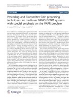
The following fi gure depicts the reference model under which 802.11 WLANs operate.
Attribute Wired LANs Wireless LANs
Data rates (2006) 10 Mb/s–10 Gb/s 1–54 Mb/s
MAC protocol CSMA/CD(Carrier Sense CSMA/CA (Carrier Sense Multiple Access/
Multiple Access/Collision Collision Avoidance)
Detection)
Range 500 m or more 50 m or less
Error rates 1 ϫ 10
Ϫ9
to 1 ϫ 10
Ϫ12
1 ϫ 10
Ϫ5
Usage Throughout the enterprise Access links to wired infrastructure
Mobility None Mobile
Medium access Typically switched (each user Typically shared (many users share a
has a separate channel) common channel)
Operating mode Connectionless Connection oriented
Interference Nearly non-existent Highly susceptible
Affected by Almost completely independent Highly affected by RF propagation
environment of surrounding environment characteristics of environment
Physical security Easy to provide Requires advanced encryption
Implementation Relatively low Highly complex
complexity
Devices connected Computers, switches, routers Computers, switches, laptops, personal
digital assistants (PDAs), phones, bar-code
scanners, RFID tags, etc.
Ch01-H7986.indd 2Ch01-H7986.indd 2 6/28/07 12:48:58 PM6/28/07 12:48:58 PM
Simpo PDF Merge and Split Unregistered Version -
IEEE 802.11 WLAN Systems
3
It is plain from the above fi gure that the wireless data links of WLANs coexist with wired
Ethernet links. WLANs normally replace the “last 30 feet” of a data communications network
to provide mobility, but are not used in the remainder of the network, where the emphasis is
on bandwidth (large servers and routers, after all, do not move about). Data traffi c carried over
WLAN links uses the Transmission Control Protocol (TCP)/Internet Protocol (IP).
1.2 WLAN Standards Today
In 1985, the Federal Communications Commission (FCC) decided to open up the so-
called ISM (Industrial, Scientifi c, and Medical) bands for use by unlicensed low-power
communication devices using spread-spectrum modulation methods. This spurred signifi cant
interest in the US in developing wireless networking equipment utilizing these bands for
computer communications (i.e., radio LANs) to serve as a radio version of the popular
Ethernet LAN technology. As a result, in 1990 the IEEE standards development organization
set up a group, referred to as the IEEE 802.11 committee, to standardize WLANs in the ISM
bands. However, it took 7 years (until 1997) before the fi rst 802.11 standard was ratifi ed and
published. That fi rst standard defi ned a relatively low-speed digital WLAN technology, with
data rate options of 1 and 2 Mb/s, and using a new Carrier Sense Multiple Access/Collision
Avoidance (CSMA/CA) medium access protocol, which was roughly modeled after the
Carrier Sense Multiple Access/Collision Detection (CSMA/CD) protocol used by half-duplex
IEEE 802.3 (Ethernet) LANs.
In parallel with the work of the IEEE committee, the European Telecommunications Standards
Institute (ETSI) started work in 1991 on a radio LAN technology called HIPERLAN (High
Performance European Radio LAN). HIPERLAN was standardized somewhat earlier than
Figure 1.1: The 802.11 Reference Model
ESS
(Extended Service Set)
BSS 1
(Basic
Service
Set)
BSS 2
Wireless
Clients
Wireless
Clients
Access
Point
Access
Point
Wired LAN
Infrastructure
(usually Ethernet)
Servers
Ch01-H7986.indd 3Ch01-H7986.indd 3 6/28/07 12:48:58 PM6/28/07 12:48:58 PM
Simpo PDF Merge and Split Unregistered Version -
Chapter 1
4
IEEE 802.11 (1996) and offered considerably more performance: 10 Mb/s, as compared to
2 Mb/s. A subsequent enhancement called HIPERLAN/2 raised this to 54 Mb/s in the year
2000. However, due to complexity and market reasons, HIPERLAN and HIPERLAN/2 have
been largely superseded by IEEE 802.11 LANs, though some of the principles of the former
have been subsequently incorporated by the latter.
WLAN standards are set today by the IEEE 802.11 Working Group (WG), which is a
subsection of the IEEE 802 LAN/MAN Standards Committee (LMSC), which in turn is a
subsection of the IEEE Standards Association and sponsored by the IEEE Computer Society.
As of this writing, the 802.11 WG has about 350 voting members and several hundred
observers, and meets six times a year to work on WLAN-related standards. The 802.11
committee works within the constraints set by various national and international regulatory
bodies to defi ne the actual radio functionality and protocol.
The IEEE 802.11 standard does not try to specify how a WLAN device should be
constructed – it leaves the design and operation of the actual clients and APs up to the
implementer. Instead, it specifi es the interactions between WLAN devices, collectively
referred to as the WLAN protocol. The purpose of the standard is to ensure interoperability
between devices without unduly constraining the device designer or vendor.
The WLAN protocol is partitioned into a number of pieces or layers:
1. The physical or PHY layer, which deals with the transmission and reception of radio
signals, and is further divided into the physical media-dependent (PMD) portion and the
PHY-layer convergence protocol (PLCP).
2. The Medium Access Control or MAC layer, which deals with the exchange of suitably
formatted packets.
3. The PHY management layer, which handles the interactions required to control the PHY
layer.
4. The MAC management layer, which likewise deals with the interactions needed to control
the MAC layer.
The 802.11 WLAN standard is thus actually a collection of related standards, specifying all
of the pieces described above. To date, there are over 25 different protocols and subprotocols
comprising the 802.11 protocol stack, each being created (or having been created) by a separate
subgroup within IEEE 802.11. The following fi gure shows a rough map of this plethora of
protocol elements. The reader should observe the caveat that, as with any dynamic standards
body, the number of protocols grows by leaps and bounds every year.
IEEE 802.11 subgroups are known as Task Groups (TGs), and are assigned letter suffi xes to
distinguish one from the other. The standards documents that they create are also assigned
Ch01-H7986.indd 4Ch01-H7986.indd 4 6/28/07 12:48:59 PM6/28/07 12:48:59 PM
Simpo PDF Merge and Split Unregistered Version -
IEEE 802.11 WLAN Systems
5
these same letter suffi xes. For example, TGg created a PHY layer standard for Orthogonal
Frequency Division Multiplexing (OFDM) transmission in the 2.4 GHz band, which promptly
became known as 802.11 g. Similarly, TGi introduced a much enhanced security system,
which was enshrined in the 802.11i standards document (more commonly known as WPA2,
after the Wi-Fi® Alliance nomenclature). A curious convention is used when assigning letter
suffi xes: lowercase letters denote standards documents that will eventually be folded into
the main 802.11 standard, while uppercase letters indicate that the document will remain
permanently stand-alone. Thus the output of the 802.11b group was folded into the main
802.11 document in 2003 (forming Clause 18), but the 802.11T group is creating the 802.11.2
document, which will remain as a stand-alone performance test specifi cation.
1
1.2.1 PHY Standards
In the US, the PHY layer of 802.11 occupies two principal microwave frequency bands: the
ISM band at 2.400–2.483 GHz, and the Unlicensed National Information Infrastructure
(U-NII) band at 5.150–5.825 GHz. (There is a further allocation in the 4.900 GHz public
service band, but this is a relatively recent development.) All 802.11 WLANs share these
frequency ranges with other users, most notably microwave ovens in the 2.4 GHz band. In
theory, as 802.11 WLANs only have a secondary allocation in these bands, a WLAN must
cease operation if it causes interference to the primary users; in practice, however, this almost
never happens, due to the low power used by 802.11 radios.
Figure 1.2: A Zoo of Protocols
1
802 standards are copyrighted by the IEEE. All 802.11 standards are available for on-line download at www.
getieee802.org, or may be ordered in electronic or paper form directly from the IEEE.
PHY AmendmentsMAC Amendments
IEEE 802.11
802.11 MAC 802.11 PHY
802.11b
(2.4GHz CCK, 1999)
802.11a
(5GHz OFDM, 1999)
802.11g
(2.4GHz OFDM, 2003)
802.11h
(Spectrum management)
802.11j
(4.9GHz Japan, 2004)
Task Group y
(3.7GHz USA)
Task Group p
(WAVE)
Task Group n
(MIMO PHY)
802.11e
(QoS, 2005)
802.11i
(Security, 2004)
Task Group k
(Radio Measurement)
Task Group u
(Interworking)
Task Group v
(WLAN Management)
Task Group w
(MFP)
Task Group T
(Performance)
Task Group r
(Fast Roaming)
Task Group s
(Mesh Networking)
802.11d
(Regulatory, 2001)
Ch01-H7986.indd 5Ch01-H7986.indd 5 6/28/07 12:49:00 PM6/28/07 12:49:00 PM
Simpo PDF Merge and Split Unregistered Version -
Chapter 1
6
The original 802.11 standard called for a 2.4 GHz time-division-duplex (TDD) radio link
with data rates of 1 and 2 Mb/s, using DBPSK and DQPSK modulation, respectively. Both
direct-sequence spread-spectrum (DSSS) and frequency-hopping spread-spectrum (FHSS)
methods were specifi ed and deployed; TDD was used to allow the uplink and downlink signals
to share the same channel, taking turns to transmit. While FHSS was generally more robust
to interference, DSSS proved to be more effi cient and fl exible, and FHSS was gradually
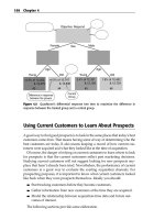
abandoned; no vendor sells 802.11 FHSS radios today. Subsequently, the 802.11b standard
added Complementary Code Keying (CCK) at 5.5 and 11 Mb/s data rates to the mix, in addition
to carrying forward the 1 and 2 Mb/s data rates of the original. The following fi gure shows the
general process used in CCK modulation. See Clause 18 of IEEE 802.11 for more information.
The data exchanged between 802.11 stations, at the PHY layer, is encapsulated within a frame
format known as the PLCP frame. PLCP frames are different for the various modulation
schemes, but generally contain a short header that indicates the coding and length of the
encapsulated MAC frame; the receiver then uses this to properly decode the frame. The PLCP
frame transmitted by an 802.11b radio is shown in the fi gure below.
The 802.11a standard was approved after the adoption of the 802.11b standard. (Actually,
work on the 802.11a standard was started prior to 802.11b, but as it used a much more
Figure 1.3: CCK Modulation Process
Add PLCP header
to MAC Frame
Scramble PLCP
frame
Divide frame into
dibits (2-bit blocks)
Encode dibits into
phase changes
Spread encoded
dibits with 8-chip
sequence
Modulate and
transmit carrier
with result
A synchronizing preamble sequence and a 48-bit header are pre-pended to the
MAC frame to create the PLCP Protocol Data Unit (PLCP frame).
The header contains rate, length and encoding information for the frame.
A self-synchronizing scrambler is run over all bits of the PLCP frame.
The scrambler ensures that long strings of ‘1’s or ‘0’s are converted to
pseudorandom data, simplifying the demodulation process.
The scrambled data is broken up into 2-bit chunks.
For 11 Mb/s encoding, a set of 4 dibits (i.e., 8 bits in all) are transmitted per
modulated symbol.
Each dibit selects one of four phase changes (0, /2, , 3/2 – i.e., DQPSK).
The mapping from dibit to phase differs based on the order of the dibit and the
bit rate (5.5 Mb/s, 11 Mb/s) being used.
An 8-chip sequence is used to generate each transmitted symbol.
The phases selected by the dibits modify the relative phases of each chip in
the sequence using a Hadamard transform.
A quadrature (I/Q) modulator is used to modulate the 2.4 GHz carrier with the
8-chip sequence produced above.
The result is filtered, amplified and transmitted.
Ch01-H7986.indd 6Ch01-H7986.indd 6 6/28/07 12:49:00 PM6/28/07 12:49:00 PM
Simpo PDF Merge and Split Unregistered Version -
IEEE 802.11 WLAN Systems
7
complex modulation scheme – OFDM – it took longer to develop than 802.11b. Hence the
puzzling inversion in the nomenclature.) The 802.11a standard operates in the 5.8 GHz band,
and calls for several different modulation types to achieve a large range of PHY bit rates. The
modulation types are not only the BPSK and QPSK used in the 1 Mb/s PHY, but also include 16-
QAM (quadrature amplitude modulation) and 64-QAM, leading to much higher data rates: 6, 9,
12, 18, 24, 36, 48, and 54 Mb/s. These modulation types are imposed on a set of 52 subcarriers
spread over a 16.6 MHz channel bandwidth. A block diagram of the OFDM modulation and
transmission process is shown below; Clause 17 of IEEE 802.11 provides details.
Sync (Scrambled Ones)
(128 bits)
SFD
(16 bits)
Signal
(8 bits)
Service
(8 bits)
Length
(16 bits)
CRC
(16 bits)
MAC Frame
Long PLCP Preamble (144 bits at 1Mb/s) Long PLCP Header (48 bits at 1Mb/s)
Sync (Scrambled Zeros)
(128 bits)
SFD
(16 bits)
Signal
(8 bits)
Service
(8 bits)
Length
(16 bits)
CRC
(16 bits)
MAC Frame
Short PLCP Preamble (72 bits at 1Mb/s) Short PLCP Header (48 bits at 2 Mb/s)
Figure 1.4: 802.11b PLCP Frame
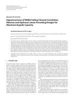
Figure 1.5: OFDM Modulation Process
Add PLCP header
to MAC Frame
Scramble PLCP
frame
Encode with
convolution code
Group bits and
modulate
Map to OFDM
subcarriers
Perform IFFT and
add cyclic prefix
A training sequence and a 40-bit header (containing rate/length information) are
added to the MAC frame to create the PLCP Protocol Data Unit (PLCP frame),
which is extended with zeros to contain an integer number of symbols.
A self-synchronizing scrambler is run over all bits of the PLCP frame.
The scrambler ensures that long strings of “1”s or “0”s are converted to
pseudorandom data, simplifying the demodulation process.
The scrambled data is encoded using a convolutional encoder for Forward Error
Correction (FEC) (coding rate R = 1/2, 2/3 or 3/4).
Some of the encoder output is omitted (‘puncturing’).
The encoded bit string is split into groups of 1, 2, 4 or 6 bits.
Each group is interleaved (reordered) to reduce the impact of error bursts,
then converted into a complex modulation value (BPSK, QPSK, 16-QAM or 64-QAM).
Each set of 48 complex modulation values is mapped to 48 different subcarriers.
Mapping is perfomed by assigning the modulation value to an inverse FFT “bucket”.
Four subcarriers are inserted as constant “pilots” to produce 52 subcarriers in all.
An IFFT is done to convert the subcarriers to the time domain (thus generating one
3.2 µs symbol).
The symbol is extended with itself and truncated to 4 µs, creating a
0.8 µs guard interval (GI) and increasing the symbol period to 4 µs.
Up-convert and
transmit
The OFDM symbols are concatenated and then used to modulate
the 2.4GHz or 5 GHz carrier.
The result is filtered, amplified and then transmitted.
Ch01-H7986.indd 7Ch01-H7986.indd 7 6/28/07 12:49:01 PM6/28/07 12:49:01 PM
Simpo PDF Merge and Split Unregistered Version -
Chapter 1
8
The 802.11a PLCP frame is different from the 802.11b frame, and is shown below.
The 802.11a PHY operates in the 5.15–5.825 GHz band, which suffers from indoor
propagation limitations. Due to market demand, therefore, the 802.11 WG began work on
extending these same data rates to the 2.4 GHz band shortly after 802.11a was published.
The result was the 802.11g standard, which incorporated all of 802.11b for backwards
compatibility, and added the OFDM modulation types from 802.11a as well, producing a
plethora of data rates: 1, 2, 5.5, 6, 9, 11, 12, 18, 24, 36, 48, and 54 Mb/s. (The specifi c data
rate to be used is selected by the transmitter according to the channel conditions, to assure
the best chance of getting the data across in the shortest time.) The 802.11g standard remains
today the most widely used WLAN physical layer.
In 2004, work was started within the 802.11 WG to specify a PHY that utilized the substantial
bandwidth gains available when using multiple antennas, a technique known as Multiple
Input Multiple Output (MIMO). This led to the formation of the 802.11n task group, which
is currently in the process of specifying a PHY capable of operating at data rates between
6.5 and 600 Mb/s in both 2.4 and 5 GHz bands. The MIMO technique will be described
in some more detail later, but in essence it uses several independently driven transmit and
receive antennas to create two or more independent “virtual” streams between a transmitter
and a receiver, and then sends different blocks of data down the various streams. The result
is a multiplication of the available bandwidth without a corresponding increase in spectrum
occupancy. The fi gure below outlines the MIMO concept.
As of this writing, the work on standardizing 802.11n is still under way. The fi nal 802.11n
standard is not expected to be ratifi ed until 2008 at the earliest, though “pre-standard”
implementations of 802.11n devices have already begun appearing on the market.
1.2.2 MAC Sublayers
The 802.11 MAC layer is necessarily a somewhat complex beast, having to deal with the
vagaries of TDD radio links and mobile users. (To illustrate this: while the formal description
Figure 1.6: 802.11a PLCP Frame
Short Training
Sequence
Long Training
Sequence
Signal
(24 bits)
Service
(16 bits)
MAC Frame
PLCP Preamble (12 symbols) PLCP Header
Tail
(6 bits)
Pad
Trailer
Rate
(4 bits)
Rsvd
(1 bit)
Length
(12 bits)
Parity
(1 bit)
Tail
(6 bits)
Ch01-H7986.indd 8Ch01-H7986.indd 8 6/28/07 12:49:01 PM6/28/07 12:49:01 PM
Simpo PDF Merge and Split Unregistered Version -
IEEE 802.11 WLAN Systems
9
of the entire 802.3 Ethernet MAC layer requires barely 15 pages, in comparison, the formal
description of the 802.11 MAC extends to over 200!) It is also blessed with no less than four
different operating modes, of which two are closely related and actually used in common
practice.
The most common 802.11 MAC operating mode is referred to rather obscurely as the
Distributed Coordination Function (DCF), and is specifi ed in subclause 9.2 of IEEE 802.11.
The DCF is a variant on the CSMA/CD half-duplex access method employed in Ethernet;
stations always listen before transmitting, and hold off (defer) to transmissions that have
started earlier. If two stations happen to transmit simultaneously, the result is a collision,
and neither station will be successful. In Time Division Duplex (TDD) radio links, however, it
is not possible to directly detect a collision, as the receiver is usually shut off (muted) during
transmit to avoid being overloaded. Instead, an indirect collision sensing scheme is used:
every transmitted packet is acknowledged, and the lack of an acknowledge indicates that the
packet was not successfully received, and should be retransmitted. This has the additional
benefi t of automatically handling the high frame error ratio of radio links – errored frames are
simply retransmitted.
MIMO Transmitter
MIMO Receiver
MAC
Forward
Error
Correction
(FEC)
Encoding
Split
Bitstream
into 4
Streams
(Stream
Parsing)
Modulate
MIMO
Space/
Time
Encoding
Inverse
FFT
Digital to Analog
Conversion
Up-
convert
PA
Up-
convert
PA
Up-
convert
PA
Up-
convert
PA
Modulate
Modulate
Modulate
LNA
LNA
LNA
LNA
Down-
convert
Down-
convert
Down-
convert
Down-
convert
Analog to Digital
Conversion
FFT
MIMO
Space/
Time
Decoding
Channel Estimation
Demodulate
Error
Detection
and
Correction
(FEC
Decoding)
T/R
T/R
T/R
T/R
Combine 4
Bitstreams
into 1 Stream
Inverse
FFT
Digital to Analog
Conversion
Inverse
FFT
Digital to Analog
Conversion
Inverse
FFT
Digital to Analog
Conversion
Analog to Digital
Conversion
FFTDemodulate
Analog to Digital
Conversion
FFTDemodulate
Analog to Digital
Conversion
FFTDemodulate
Figure 1.7: MIMO PHY
Ch01-H7986.indd 9Ch01-H7986.indd 9 6/28/07 12:49:02 PM6/28/07 12:49:02 PM
Simpo PDF Merge and Split Unregistered Version -
Chapter 1
10
Further, the DCF utilizes a scheme for collision avoidance, forcing prospective transmitters
to wait for random lengths of time – the backoff interval – in the hope of preventing two
transmitters from attempting to get on the air simultaneously. The access method used by
802.11 is therefore referred to as CSMA/CA.
A variant of the DCF is specifi ed by the recently adopted 802.11e standard for prioritizing
medium access for real-time, delay-sensitive traffi c such as voice or video. Referred to as
Enhanced Distributed Channel Access or EDCA, it basically uses a probabilistic scheme,
forcing lower priority stations to wait for longer times in order to access the medium, while
higher priority stations suffer a generally lower delay. This results in voice or video traffi c
obtaining preferential access to the wireless medium, while data traffi c takes what bandwidth
is left.
The two other operating modes are referred to as the Point Coordination Function (PCF) and
Hybrid Coordination Function (HCF) Controlled Channel Access (HCCA). The PCF is a
centralized, polling-based access method, where the AP is responsible for controlling which
stations are permitted to transmit, and polling all stations using special control packets to
determine if they need to send data. HCCA is the QoS variant of PCF, and defi ned in 802.11e.
Neither are commonly used in operating WLANs today – in fact, the author is not aware of
any equipment that even implements PCF – and so will not be described further.
In addition to the basic channel access functions, the 802.11 standard encompasses a number
of extensions and additional protocols for security, QoS support, radio channel and neighbor
station assessment, roaming, etc. The original security method provided for by 802.11 was
the infamous WEP (Wired Equivalent Privacy) protocol, which relied on fi xed, manually
confi gured encryption keys for the RC4 encryption protocol. The 802.11i standard rectifi ed
three of the biggest fl aws of WEP – weak encryption keys, manual confi guration, and lack
of protection against replay attacks – with a much more comprehensive scheme utilizing
the IEEE 802.1X protocol for dynamic generation and distribution of encryption keys.
Similarly, the 802.11e standard added QoS functions to 802.11 networks. In addition to
defi ning the EDCA and HCCA prioritized medium access methods, the 802.11e standard
Frame
Station A
Station B
Frame
Frame
Frame
A
C
K
A
C
K
Frame
DIFS Backoff
Station B
Ready to
Transmit
Station B Defers to Station A,
and then backs off
SIFS
SIFS DIFS Backoff
EIFS
EIFS Backoff
Collision
Stations A and
B Transmit at
Same Time
Station B
Retransmits
Successfully
Figure 1.8: DCF Medium Access (see subclause 9.2.5, IEEE 802.11)
Ch01-H7986.indd 10Ch01-H7986.indd 10 6/28/07 12:49:02 PM6/28/07 12:49:02 PM
Simpo PDF Merge and Split Unregistered Version -