Chapter 10 Shafts.pdf
Bạn đang xem bản rút gọn của tài liệu. Xem và tải ngay bản đầy đủ của tài liệu tại đây (1.19 MB, 18 trang )
1 11/20/2023
1
DEPARTMENT OF EDUCATION AND TRAINNING
HOCHIMINH CITY UNIVERSITY OF TECHNOLOGY
AND EDUCATION
THEORY OF MACHINE AND MACHINE DESIGN
CHAPTER 10: SHAFT
20-Nov-23
2
Outcome
1. Getting the overview of shaft
2. Understanding the
mechanical properties of shaft
3. Calculating and design shaft
TS. Phan Cơng Bình 20-Nov-23
3
Theorical contents
I. Overview
II. Basic criteria of calculation
III. Fundamentals of calculation
and design
TS. Phan Cơng Bình 20-Nov-23
4 Rotating component 11/20/2023
Pulley, gear, sprocket,… 2
Overview assemble with shaft
Coupling component
- Shaft (Trục)
- Bearing (Ổ trục)
- Couplings (Khớp nối)
Most of mechanical machinery and equipment contain shaft
TS. Phan Cơng Bình 20-Nov-23
Overview
1. Application
a. Supporting component (bending)
+ Shaft with a neutral wheel
+ Shaft assemble with neutral gear
b. Transmitting torque (twist)
+ Driving shaft
+ Transmitting shaft
Almost shafts are used to support and transmit torque
TS. Phan Cơng Bình
Overview
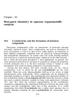
2. Classification
a. Based on load
+ Axles (Trục tâm) are subjected only to bending
+ Shaft (Trục truyền) are intended not only to support revolving parts but also to
transmit torque
Axles Shaft
TS. Phan Cơng Bình
Overview 11/20/2023
3
2. Classification
a. Based on load
+ Parallel drive (trục truyền chung) are applied to transmit torque to multi-component
at the same time
Parallel drive
TS. Phan Cơng Bình
Overview
2. Classification
b. Centerline (đường tâm)
+ Straight shaft (Trục thẳng)+ Crank shaft (Trục khuỷu)+ Flexible wire shaft (Trục mềm)
Crank shaft
Straight shaft
Flexible wire shaft
(Trục mềm)
TS. Phan Cơng Bình
Overview
2. Classification
c. Structure (Kết Cấu )
+ Plain shaft: constant diameter (Trục trơn)
+ Step shaft: Changing diameter (Trục bậc)
TS. Phan Cơng Bình
Overview 11/20/2023
4
2. Classification
d. Cross-section (Tiết diện)
+ Solid shaft (Trục đặc)
+ Hollow shaft ( Trục rỗng)
Solid shaft Hollow shaft
TS. Phan Cơng Bình
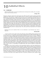
11 Overview
3. Shaft material
Technical requirement:
Reducing the stress concentration (giảm tập trung ứng suất)
Manufacturing and Maintenance Technology (có tính cơng nghệ)
Common material : Carbon steel (thép carbon)
Alloyed steel (thép hợp kim)
* Common carbon steel:
CT3, CT5, C30, C40, C45, C50
C45 has 0.45% carbon the most common steel in the world
* Common alloyed steel:
40CrNi, 40CrNi2MoA, 30CrMnTi, 30CrMnSiA
20Cr, 12CrNi3A, 18CrMnTi
TS. Phan Cơng Bình
12 Overview
4. Structure
a. Journal (ngõng trục): Using to assemble bearings
b. The clamped parts (thân trục): Used to mount
the rotating component
c. Transitions location: Between 2 different diameter on
shaft
p
t
d. Another surface: Key sitting (rãnh then), fillet
(góc lượn),… d
Requirements of shaft structure
+ Strength: Satisfying the technical requirements
+ Technology: Ability of processing disassemble, assemble and
maintenance
+ Reduce stress concentration : Fillet suitable to structure
= 0.02 ÷ 0.04; ≈3( ) 20-Nov-23
TS. Phan Cơng Bình
13 Overview 11/20/2023
5. Pattern failures and Design method 5
a. Break (gãy)
Overload or fatigue
Strength
validation
TS. Phan Cơng Bình 20-Nov-23
14 Overview
5. Pattern failures and Design method
b. Deformation (biến dạng)
Not enough to rigidity (Không đủ độ cứng)
rigidity
TS. Phan Cơng Bình 20-Nov-23
15 Overview
5. Pattern failures and Design method
c. Vibration (dao động)
Rotating Component is off centerline (lệch tâm)
Vibration
TS. Phan Cơng Bình 20-Nov-23
16 11/20/2023
6
Theorical contents
I. Overview
II. Basic criteria of calculation
III. Fundamentals of calculation
and design
TS. Phan Cơng Bình 20-Nov-23
17 Basic criteria calculation of shaft
1. Calculating strength
Sequence of calculation and design
a. Preliminarily calculation (Tính sơ bộ)
- No shaft structure
- According to torque (twist only) - (chỉ tính momen xoắn)
- Calculating diameter preliminarily
- (Tính đường kính sơ bộ)
- Selecting bearing preliminarily, sketch out (phát thảo) shaft structure
b. Calculating strength (Tính sức bền tĩnh)
- Determining the acting force (torque and bending) and Reactive force
- Calculating exactly shaft diameters at critical cross sections and selecting
parameter based on standard)
- Design shaft structure
c. Examining (Tính kiểm nghiệm)
- Examining overload (kiểm nghiệm quá tải)
- Examining strength and fatigue (kiểm nghiệm độ bền mỏi)
TS. Phan Cơng Bình 20-Nov-23
18 Basic criteria calculation of shaft
1. Calculating strength
a. Preliminary calculation (Tính sơ bộ)
Selecting material and allowable torque [ ′], MPa
= = ≤ [ ′]
.
where, T is a torque acting on shaft, N.mm
=> The preliminary shaft d, mm
5 Vị trí xác định đường kính:
≥ + Đầu trục đối với trục vào và ra
+ Thân trục lắp bánh dẫn với trục trung gian
′
Selecting preliminary bearing and sketch out shaft structure
TS. Phan Cơng Bình 20-Nov-23
19 Basic criteria calculation of shaft 11/20/2023
7
1. Calculating strength
b. Calculating strength
- Determining all forces acting on shaft
- Calculating the support reactions (Phản lực) at pins (Gối đỡ)
- Drawing the diagram of bending or torque moment
- Obtaining exactly diameter of shaft by using the IV strength theory
- Completing the shaft structure
TS. Phan Cơng Bình 20-Nov-23
20 Basic criteria calculation of shaft
1. Calculating strength
b. Calculating strength
Based on IV strength theory (Thuyết bền 4)
= =
0.1
đ = + 3 ≤ , where,
=
= 0.2
The value Mtđ determining by formula đ= + 0.75
đ đ
đ = 0.1 ≤ ≥
0.1
Note: - Key seat (Rãnh then) increases d about 6-10%
- Diameter of journal must be standardized in (TLTK)
TS. Phan Cơng Bình 20-Nov-23
21 Basic criteria calculation of shaft
1. Calculating strength
Examble:
Design shaft I with the parameter in picture. Material C35 has allowable twist
torque [ ′]=20 Mpa and =20 Mpa .
Belt force acting on shaft Fđ = 791.8N and
Force acting on gearing Fr1 = 1178.9N , Ft1 = 3239N
Fđ=791.8N Fr1=1178.9N
P1=5.66kW Ft1=3239N Oz
T1=181385Nmm B
A
C D
n1=298v/p x
y
TS. Phan Cơng Bình 20-Nov-23
22 Basic criteria calculation of shaft 11/20/2023
8
1. Calculating strength
+ Calculating diameter preliminary
≥ = 35.6 mm;
Selecting diameter based on standard d = 36 mm,
+ Sketch out shaft structure
- Selecting diameter of shaft based on standard
f=90 l=145
d=36 d=40 d=40
d=36
TS. Phan Cơng Bình 20-Nov-23
23 Basic criteria calculation of shaft
1. Calculating strength
+ Determining the equivalent moment at cross-section j Mtđ
đ= + + 0.75
+ Calculating shaft diameter at cross-section
≥đ f=90 l=145
0.1
Selecting dj according standard d=40
d=45
d=40
+ Completing structure
Ability of processing disassemble, assemble and maintenance
TS. Phan Cơng Bình 20-Nov-23
24 Basic criteria calculation of shaft
1. Calculating strength
c. Examining
• Examining over load
= +3 ≤ = 0.8 ℎ
where,
, bending and torque at danger cross − section
, ℎ allowable stress when overload and elastic (chảy)
• Examining strength and fatigue
safety factor 1.5~2.5
= + ≥[ ] , safety factor of bending and torque
TS. Phan Cơng Bình 20-Nov-23
25 Basic criteria calculation of shaft 11/20/2023
9
2. Calculating rigidity. Condition of rigidity: f≤[ ]
a. Rigidity ≤
F
f
+ [f] = 0,01m – Shaft assemble with cylindrical gears
+ [f] = 0,005m – Shaft assemble with bevel gears
+ [] = 0,01rad - Thrust bearing (ổ bi đỡ)
+ [] = 0,05rad- Ball bearings (ổ bi lòng cầu)
+ [] = 0,001rad – Friction bearing (ổ bi trượt)
In machine manufacturing, we can be selected : [f] =(0,0002 ÷ 0,0003)I
where, l: Pin distance.
TS. Phan Cơng Bình 20-Nov-23
26 Basic criteria calculation of shaft
2. Calculating rigidity.
b. Torsional deflection
Basic criterial of Torsional deflection of shafts:
= ≤[ ]
where,
[ ]: allowable angel of twist (góc xoắn cho phép), rad
G: shear modulus module (trượt đàn hồi) G=8,3.104,MPa
J0: moment of inertia in torsional (moment quán tính) (J0= /32)
l: length of twist (chiều dài đoạn trục xoắn), mm
TS. Phan Cơng Bình 20-Nov-23
27 Basic criteria calculation of shaft
3. Calculating oscillation.
a. Cause
- Off centerline generate external
forced generate vibration (dao
động)
b. Damage
- Making additional stress (ứng suất phụ)
=> Effecting on strength
- Resonance (vùng cộng hưởng)
=> Breaking shaft
TS. Phan Cơng Bình 20-Nov-23
28 Basic criteria calculation of shaft 11/20/2023
10
3. Calculating oscillation.
c. Criteria of calculation
- Calculating amplitude ≤ [ ]
- Determining resonance (vùng cộng hưởng).
TS. Phan Cơng Bình 20-Nov-23
29 Basic criteria calculation of shaft
3. Calculating oscillation.
d. Oscillation problems
- According the off-centerline m
= e
where, ey
l/2 l/2 l/2 Flt l/2
= = (+)
( )= − =
−1
f= = (natural frequency) → ∞ ( )
48
= The rigidly of shaft (TLTK)
Notice: Danger working conditions ≈ ( . ÷ . )
TS. Phan Cơng Bình 20-Nov-23
30
Theorical contents
I. Overview
II. Basic criteria calculation of
shaft
III. Fundamentals of calculation
and design
TS. Phan Cơng Bình 20-Nov-23
31 11/20/2023
11
Fundamentals of calculation and design
Notice:
Moment
Bending Fa =
Torque Ft = ∗ = ∗
Sequence of calculation
1. Analyzing acting force in 2 plane (coordinates) Oz
• Plane: yoz (Fr & Ma ) x
• Plane: xoz (Only Ft) y
2. Calculating support reaction at pins on shaft
3. Drawing moment diagram (From left to right)
4. Determine diameter at critical cross-section
TS. Phan Cơng Bình 20-Nov-23
32
Fundamentals of calculation and design
1. Calculating force acting
a. Specifying gears parameter
- Determining the pitch diameter by formula :
+ Spur gear : d = mz1 (mm)
+ Helical gear: d = mnz1/cosβ (mm)
+ Bevel gear: d = mmz1 (mm)
where,
m – module
z – Number of teeth on gear
β – Helix angle
TS. Phan Cơng Bình 20-Nov-23
33
Fundamentals of calculation and design
1. Calculation acting force
b. Obtaining the acting Force
- Radial force Fr : Fr 2F0 sin(α1 / 2) (N)
+ V belt:
+ Chain: 7
Fr kxFt 6.10 kxP / zpn (N)
- Tangential force on coupling Ft : Ft = 2T/Dkn (N)
where,
+ Dkn – coupling diameter (đường kính khớp nối) (mm)
+ T – twist torque (N.mm)
The radial acting force on shaft Fr due to misalignment can be calculated by
Fr (0.2 0.3)Ft
TS. Phan Cơng Bình 20-Nov-23
34 11/20/2023
12
Fundamentals of calculation and design
2. Analysis the acting force
a. Force acting diagram
- The Figure describes force acting diagram of transmission
+ Fa2 x X
+Ft2 Fr2
Fxx
Ft1 Fxy
Fa1
z
Fr1
x
Fkn xy
TS. Phan Cơng Bình 20-Nov-23
35
Fundamentals of calculation and design
3. Determining diameter of shaft
b. Drawing moment diagram
TS. Phan Công Bình 20-Nov-23
36
+ L1 = L2 = L3 = 125mm
+ Ft1 = 500N, Fr1 = 182N
+ Ft2 = 800N, Fr2 = 291N
+ T = 50000 N.mm
Reaction force at pin A and D:
+ RAY = 24.3 N, RDY = 133.3 N
+ RDX = 700 N, RAX = 600 N 20-Nov-23
TS. Phan Cơng Bình
Exercise 11/20/2023
13
Q 1 Given the shaft of transmission system, Torque on shaft T = 100000 Nmm.
Helical gears, mn = 2 mm and helix gear β = 12o. The number of teeth on gearing:
Z1 = 22 and Z2 = 67. The yield stress of shaft material is [σF] = 60 MPa.
Calculating the force acting on shaft?
Helical gears
d1 mnZ1 2T Fr 1 Ft1 tan α 1655N Fa1 Ft1 tan β 945N
cos β Ft1 4446N
cos β
44,98mm d1
d2 mnZ2 2T Fr 2 Ft 2 tan α 543N Fa2 Ft2 tan β 310,32N
cos β Ft2 1459,9N
cos β
d2
Spur gears 2T Fr 2 Ft 2 tan α Fa2 0
d2 mZ2 Ft 2
d2
TS. Phan Cơng Bình
38
Exercise
Q 2 Gear 1 = 400 ; Gear 2 = 160 .
Tangential force = 1000 and radial force = 364
Tangential force = 2500 and radial force = 910
Lengths = 150 , = 250 , = 150 .
Allowable stress = 50
a.Determining the reaction support at pin B and C
b.Drawing moment diagram , , T
c. Determining diameter at cross-section
Oz
x
y
TS. Phan Cơng Bình 20-Nov-23
39 Exercise
Q 2 2.a The reactive force at pin B and C:
+ The moment equation at B in Y direction (at point B)
=− ∗ + − ∗ + =0
= ∗ ∗ = ∗ ∗( ) = ,
+ The force equation: (at point C)
=− + + − =0
= + − = 1674,3 + 364 − 910 = ,
+ The moment equation at B in X direction (at point B)
∑ =− ∗ − ∗ + ∗ + =0
= ∗ ∗ ∗ ∗( ) =
=
+ The force equation (at point C)
= − − + =0
= − + + = −3400 + 1000 + 2500 =
TS. Phan Cơng Bình 20-Nov-23
40 11/20/2023
14
Exercise
Q 2
2.b
TS. Phan Cơng Bình 20-Nov-23
41
Exercise
Q 2
2.b
TS. Phan Cơng Bình 20-Nov-23
42
Exercise
Q 2
2c Diameter at danger cross-section C:
Equivalent moment at C:
đ= + + 0,75
= 136489 + 375000 + 0,75 ∗ 200000
=
Diameter of shaft at cross-section C:
≥ đ =,
0,1 ∗
For assembling bearing at C we choose dc= 45 mm
TS. Phan Cơng Bình 20-Nov-23
43 11/20/2023
15
Exercise
Q 3 a. Determining the reaction
support at pin B and C
Given the working shaft in picture 3. b.Drawing moment diagram ,
The helical gear parameter
,T
= 240 , = 5000 , = 1885 , c. Determining the diameter of
= 1340 . shaft at danger cross-section C
The spur gear parameter
= 120 , = 10000 , = 3640 .
Length
= 120 , = 150 , = 150 .
Yield stress = 60 .
TS. Phan Cơng Bình 20-Nov-23
44
Exercise
Q 3
Determining the reaction support at pin B and C
= = 1340 ∗ 120 = ;
= ∗= ∗=
2 2
+ The moment equation at B in Y direction : ∗( + )=0
= ∗− + ∗−
= ∗ ∗ = ()
+ The force equation: ∑ = − − + = 0
=− + + = ()
+ The moment equation at B in X direction :
∑ =− ∗ + ∗+ ∗( + )=0
()
= ∗ ∗ =
( )
+ The force equation: ∑ = − + − − =0
=> = + + = ()
TS. Phan Cơng Bình 20-Nov-23
45
Exercise
Q 3
4.b
In yoz plane: Fr or Ma
Ma1
In xoz plane: only Ft
TS. Phan Cơng Bình 20-Nov-23
46 Exercise 11/20/2023
16
Q 3 + Equivalent moment at C:
đ= + + 0.75
= 440100 + 225000 + 0,75 ∗ 600000 =
Diameter of shaft at cross-section C:
≥ đ ≥.
0.1
For assembling gear at C, we choose: = ( )
Bonus:
+ Equivalent moment at B:
đ= + + 0.75
= 436764 + 1200000 + 0.75 ∗ 600000 =
Diameter of shaft at cross-section C::
≥ đ =,
0.1
For assembling bearing at B, we choose: = ( )
TS. Phan Cơng Bình 20-Nov-23
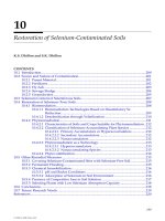
Exercise 1 = 325 ,
2 = 486 .
Q 4 The bevel gear 1 : = 200 , 1 = 1000 , 1 = 163 ,
and helical gear Z2 2 = 160 , 2 = 1250 , 2 = 465 ,
Distance 1 = 100 , 2 = 200 , 3 = 100 .
The allowable bending stress [ ] = 60 .
a. Determine the reaction support at pin A and D.
b. Drawing the moment diagram Mx, My and T.
c. Determining the diameter of shaft at danger cross-section B.
TS. Phan Cơng Bình
Exercise
Q 4
TS. Phan Cơng Bình
Exercise 11/20/2023
Q 4 17
TS. Phan Cơng Bình
Exercise
Q 4
In yoz plane: Fr or Ma Ma1
TS. Phan Cơng Bình Ma2
Exercise
Q 4
In xoz plane: only Ft
TS. Phan Cơng Bình
11/20/2023
Exercise
Q 4
TS. Phan Cơng Bình
53
TS. Phan Cơng Bình 20-Nov-23
18