Chapter 6 Chain Drive.pdf
Bạn đang xem bản rút gọn của tài liệu. Xem và tải ngay bản đầy đủ của tài liệu tại đây (2.96 MB, 11 trang )
1 20/3/2023
1
DEPARTMENT OF EDUCATION AND TRAINNING
HOCHIMINH CITY UNIVERSITY OF TECHNOLOGY AND EDUCATION
THEORY OF MACHINE AND MACHINE DESIGN
CHATER 5: CHAIN DRIVES
20-Mar-23
2
Target
1. Understanding the basic of
chain drives
2. Understanding dynamic of
the chain drives
3. Design the chain drives
TS. Phan Cơng Bình 20-Mar-23
3
Theoretical contents
I. Overview
II. Sequence of calculation and
design the chain drives
III. Exercise
TS. Phan Cơng Bình 20-Mar-23
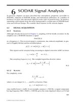
4 Overview 20/3/2023
2
1. Structure
3
2
4
4 1
1. Driving sprocket 2. Driven sprocket 3. Chain 4. Chain tensioner
TS. Phan Cơng Bình 20-Mar-23
5
Overview
2. Geometrical parameters
d1, Z1 pitch diameter and number of teeth on the sprocket 1
d2, Z2 pitch diameter and number of teeth on the driven sprocket 2
a: Centre distance
TS. Phan Cơng Bình 20-Mar-23
6
Overview
3. Operating principle.
Movement and load are transmitted from the driving sprocket to the
driven sprocket based on the principle of matching in chain drive.
TS. Phan Cơng Bình 20-Mar-23
7 Overview 20/3/2023
3
3. Operating principle.
A chain tensioner is applied to increase the performance of the drive
TS. Phan Cơng Bình 20-Mar-23
8 Overview
4. Classification
Based on structure :
Roller chain.
Bush chain.
Inverted tooth chain.
TS. Phan Cơng Bình 20-Mar-23
9 Overview
4. Classification
Based on lines of chain:
1 line chain.
Multiple lines chain.
TS. Phan Cơng Bình 20-Mar-23
10 Overview 20/3/2023
4
4. Classification
Based on the load mode:
Chain drive Conveyor chain Lifting chain
TS. Phan Cơng Bình 20-Mar-23
11 synchronized chain drive
Overview
5. Advantages and disadvantages
Advantages:
Far center distance transmission (<8m).
Less tension adjustment
small force effected on shaft
No sliding
Smaller structure compared to belt drives
Long lifetime.
Transmit to multiple shaft at the same time
(synchronized function)
TS. Phan Cơng Bình 20-Mar-23
12
Overview
5. Advantages and disadvantages
Disadvantages :
Cause noise due to impact
Unstable instantaneous ratio.
Complex in manufacturing,
assembly and maintenance .
TS. Phan Cơng Bình 20-Mar-23
13 Overview 20/3/2023
5
6. Application
TS. Phan Cơng Bình 20-Mar-23
14
Overview
pc
7. Broken patterns
Hinge Abrasion increasing pitch Out of chain.
pc
Broken roller
TS. Phan Cơng Bình 20-Mar-23
15
Theoretical contents
I. Overview
II. Sequence of calculation and
design the chain drives
III. Exercise
TS. Phan Cơng Bình 20-Mar-23
16 20/3/2023
6
Sequence of calculation and design the chain drives
1. Initial parameters
P1 (kW) Power on the driving sprocket
n1 (rpm) Rotation speed of the driving sprocket
u Ratio
2. Determine parameters of chain drives
Chain selection: => Roller chain
Number of teeth on sprocket:
Z1 29 2u
Z2 uZ1
(Roller chain11 15 < Z < 100 120)
Z should be odd number
TS. Phan Cơng Bình 20-Mar-23
17
Sequence of calculation and design the chain drives
2. Determine parameters of chain drives
Calculation pitch of chain directly by the following equation :
pc 2.823 KT1 6003 KP1
Z1p0 K x Z1n1p0 K x
Based on satisfied standard abrasion and searched in Table 5.4 ([P] and n01)
Pt K Kz Kn P1 P
Kx
TS. Phan Công Bình 20-Mar-23
18
Sequence of calculation and design the chain drives
2. Determine parameters of chain drives
Based on n1 to determine n01 (the closest given range)
Based on n01 and Pt , [P] is selected in Table 5.4
pc [P]
n01 n01=50 n01=200 n01=400 …..
pc
[P]
pc Pt<[P]
TS. Phan Cơng Bình 20-Mar-23
19 20/3/2023
7
Sequence of calculation and design the chain drives
2. Determine parameters of chain drives n1=350 rpm
Pitch of Pin Length of Pt=5.5 kW
chain diameter Bushing Allowable power [P], kW, rotation speed of driving sprocket
(mm) dc,(mm)
(mm) n01 ,(rpm)
50 200 400 600 800 1000 1200 1600
12,7 3,66 5,80 0,19 0,68 1,23 1,68 2,06 2,42 2,72 3,20
12,7 4,45 8,90
12,7 4,45 11,30 0,35 1,27 2,29 3,13 3,86 4,52 5,06 5,95
15,875 5,08 10,11
15,875 5,08 13,28 0,45 1,61 2,91 3,98 4,90 5,74 6,43 7,55
19,05 5,96 17,75
25,4 7,95 22,61 0,57 2,06 3,72 5,08 6,26 7,34 8,22 9,65
31,75 9,55 27,46
38,1 11,12 35,46 0,75 2,70 4,88 6,67 8,22 9,63 10,8 12,7
44,45 12,72 37,19
50,8 14,29 45,21 1,41 4,80 8,38 11,4 13,5 15,3 16,9 19,3
3,20 11,0 19,0 25,7 30,7 34,7 38,3 43,8
5,83 19,3 32,0 42,0 49,3 54,9 60,0 -
10,5 34,8 57,7 75,7 88,9 99,2 108 -
14,7 43,7 70,6 88,3 101 - - -
22,9 68,1 110 138 157 - - -
TS. Phan Cơng Bình 20-Mar-23
20
Sequence of calculation and design the chain drives
2. Determine parameters of chain drives
Kx is coefficient of uneven load distribution depend on lines of chain :
Lines of chain 12 3 4
Kx 1 1.7 2.5 3
Kz coefficient of the teeth number on the driving sprocket :
K z Z01 25
Z1 Z1
Kn coefficient of the rotating speed of the driving sprocket:
Kn n01
n1
TS. Phan Cơng Bình 20-Mar-23
21
Sequence of calculation and design the chain drives
2. Determine parameters of chain drives
K = Kr KaK0KdcKbKlv
Kr – Coefficient of Dynamic load:
+ Smooth performance Kr =1,
+ Impact load Kr =1,2÷1,5;
+ Strong impact load Kr =1,8.
Ka – Coefficient of center distance
TS. Phan Cơng Bình 20-Mar-23
22 20/3/2023
8
Sequence of calculation and design the chain drives
2. Determine parameters of chain drives
K0 – Coefficient of the drive position. The angle taken by the
center line and the horizontal line is smaller than 60o K0 = 1,25.
Kdc – Coefficient of ability to adjust chain tension:
+ Kdc = 1 for center distance adjustment
+ Kdc = 1,1 for employing chain tensioner
+ Kdc =1,25 for chain drive can not adjust tension
Kb Coefficient of lubrication conditions:
+ Kb = 0,8 for continuously lubricating;
+ Kb = 1; for dripping lubricating
+ Kb = 1,5 for periodic lubricating.
Klv – Coefficient of working shift a day
+ Klv = 1 for 1 shift
+ Klv = 1,12 for 2 shifts
+ Klv = 1,45 for 3 shifts
TS. Phan Cơng Bình 20-Mar-23
23
Sequence of calculation and design the chain drives
2. Determine parameters of chain drives
Pitch circle diameter d1 pc d2 pc
sin sin
Z1 Z2
Chain link x must be even number
𝑥 = 2𝑎 + 𝑍1 + 𝑍2 + 𝑍2 − 𝑍1 𝑝𝑐
𝑝𝑐 2 2𝜋 𝑎
Centre distance
a = 0.25𝑝 [𝑥 − + 𝑥 − −8 ]
Note: d2 should be smaller than 600(mm), or it is limited by the specific conditions.
Then, lines of chain can be increased to reduce d2
TS. Phan Cơng Bình 20-Mar-23
24
Sequence of calculation and design the chain drives
3. Validation of chain drive dynamic
a. Instantaneous velocity and ratio of chain drive
Instantaneous velocity:
v2 v1 cos
cos
Z1 Z1 Z2 Z2
Instantaneous ratio:
Z cos
2 const
u t Z1 cos
TS. Phan Cơng Bình 20-Mar-23
25 20/3/2023
9
Sequence of calculation and design the chain drives
3. Validation of chain drive dynamic
b. Average velocity and ratio chain
Average velocity:
v1 4 Z1 pc n1
6.10
v2 4 Z 2 pc n2
6.10
Average ratio chain:
u n1 Z2
n2 Z1
TS. Phan Cơng Bình 20-Mar-23
26
Sequence of calculation and design the chain drives
3. Validation of chain drive dynamic
Checking the number of impact per second.
To limit the impact kinetic energy E, the number of impacts per second is
defined as:
i Z1n1 [i] [i] search in Table 5.6
15x
Table 5.6 The allowable number of impact in second
Type of chain Pitch of chain pc, (mm)
12,7 15,875 19,05 25,4 31,75 38,1 44,45 50,8
Roller chain 40 30 25 20 16 14 12 10
Inverted tooth chain 60 50 40 25 20 - - -
TS. Phan Công Bình 20-Mar-23
27
Sequence of calculation and design the chain drives
4. Calculating chain by resistance.
Condition: The pressure generated on the contact surface of the pin and
hinge p must be less than the allowable pressure [p] of material wrapped
p F [p]
bushing.
A
Because of difference of experimental condition.
[p]= [p0 ]
K
Allowable pressure[p0] search in Table 5.3.
Pitch of chain Allowable pressure in hinge of chain[po], (MPa) rotating speed of
pc (mm) driving sprocket n1, (rpm)
50 200 400 600 800 1000 1200 1600 2000
12,7 ÷ 15,875 35 31,5 28,5 26 24 22,5 21 18,5 16
–
19,05 ÷25,4 35 30 26 23,5 21 19 17,5 15 –
31,75 ÷ 38,1 35 29 –
44,45 ÷ 50,8 35 26 24 21 18,5 16,5 15 –
20-Mar-23
21 17,5 15 – – –
TS. Phan Cơng Bình
28 20/3/2023
10
Sequence of calculation and design the chain drives
5. Force Analysis acting on shaft
Initial force F0
F0 = Kf qm a g (N)
Kf : Coefficient of chain deflection
+ Kf =1 for vertical position of chain drive
+ Kf =3 for angle smaller 400
+ Kf =6 for horizontal position of chain drive
qm : Mass of 1m chain (kg).
a: Centre distance (m).
Auxiliary Fv.
Fv = qm v2 (N)
TS. Phan Cơng Bình 20-Mar-23
29
Sequence of calculation and design the chain drives
5. Force Analysis acting on shaft
Tension force in each side
F2 = F0 + Fv (N)
F1 = F2+ Ft (N)
Ft= 2T1/d1 (N)
Force acting on shaft Fr
Fr = K m Ft (N)
Km is dependent on the angle between the center line with the horizontal line
+ Km=1.15 for angle smaller 400
+ Km=1 for angle from 400 to 900.
TS. Phan Cơng Bình 20-Mar-23
30 Problems
Q1: There is two lines of Roller chain. Transmission Power P1= 5,5 Kw and the rotating
speed of driving sprocket n1=380rpm. Teeth on driving sprocket and driven sprocket
are Z1=23 and Z2=63, respectively. The working condition coefficient K=1,8. Allowable
power of roller chain are given in Table 1.
a. Based on standard abrasion, determine pitch of chain pc of the chain drive
b. Determine pitch circle diameters
Table 1. Allowable power of roller chain
Pitch of Allowable power [P], kW, rotating speed of driving sprocket n01(rpm)
chain
p (mm) 50 200 400 600 800 1000 1200 1600
12,7 0,35 1,27 2,29 3,13 3,86 4,52 5,06 5,95
12,7 0,45 1,61 2,91 3,98 4,90 5,74 6,43 7,55
15,875 0,57 2,06 3,72 5,08 6,26 7,34 8,22 9,65
15,875 0,75 2,70 4,88 6,67 8,22 9,63 10,8 12,7
19,05 1,41 4,80 8,38 11,4 13,5 15,3 16,9 19,3
25,4 3,20 11,0 19,0 25,7 30,7 34,7 38,3 43,8
31,75 5,83 19,3 32,0 42,0 49,3 54,9 60,0 -
TS. Phan Cơng Bình 20-Mar-23
31 Problems 20/3/2023
11
Q1: Solve
a. Determine pc:
+ 2 lines of chain: => Kx=1,7
+ n1=380rpm => n01=400rpm
Kz Z01 25 1, 09 KKK
Z1 23 Pt P1 z n 6,7 kW
n01 400 Kx select pc=19,05mm
Kn 1,05
n1 380
n01=400rpm
Pt [P] 8,38 kW
b. Determine the pitch circle diameters :
𝑝
𝑑 = 𝜋 = 𝟏𝟑𝟗, 𝟗𝑚𝑚
sin(𝑍 )
𝑝
𝑑 = 𝜋 = 𝟑𝟖𝟐, 𝟐𝑚𝑚
sin(𝑍 )
TS. Phan Cơng Bình 20-Mar-23
32
Bài tập ứng dụng
Q. 2
Roller chain drive has 2 lines of chain, pitch of chain pc=25,4; teeth on driving
sprocket Z1=23, Z2=63. Rotating speed of driving sprocket n1=380rpm.
Center distance a=40pc and coefficient K=1,7.
Determine:
1. Pitch circle diameters
2. Chain links
3. Maximum power P1 (kW)
TS. Phan Cơng Bình 20-Mar-23
33
TS. Phan Cơng Bình 20-Mar-23