Chapter 5 Belt Drive.pdf
Bạn đang xem bản rút gọn của tài liệu. Xem và tải ngay bản đầy đủ của tài liệu tại đây (2.91 MB, 14 trang )
1 14/3/2023
1
DEPARTMENT OF EDUCATION AND TRAINNING
HOCHIMINH CITY UNIVERSITY OF TECHNOLOGY
AND EDUCATION
THEORY OF MACHINE AND MACHINE DESIGN
Chapter 4: BELT DRIVES
14-Mar-23
2
Target
I. Overview of belt drives
II. Understand the mechanism of
transmission problems
III. Calculation and design
drives belts
TS. Phan Cơng Bình 14-Mar-23
3
Theoretical contents
I. Overview
II. Sequence of calculation and
design the belt drives
III. Exercise
TS. Phan Cơng Bình 14-Mar-23
4 14/3/2023
2
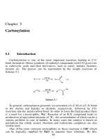
Overview
1. Structure.
3
3
4
2
1
1. Driving pulley 2. Driven pulley 3. Belt 4. Idler pulley
TS. Phan Cơng Bình 14-Mar-23
5 Overview
2. Operating principle.
Depend on friction force between belt and pulley.
Movement and energy are transmitted from driving pulley to driven pulley
TS. Phan Cơng Bình 14-Mar-23
6 Overview
2. Operating principle.
Belt tension generates friction force.
TS. Phan Cơng Bình 14-Mar-23
7 Overview 14/3/2023
3
3. Classification.
Cross-section of belt:
• Flat belt.
• V belt.
• Ribbed belt.
• Round belt.
• Timing belt
TS. Phan Cơng Bình 14-Mar-23
8 Overview
3. Classification.
Flat belt :
• Cross section 𝑏𝑥𝛿 𝑚𝑚 .
• Include: leather belt, rubber belt, ...
TS. Phan Cơng Bình 14-Mar-23
9 Overview
3. Classification.
V belt :
• Isosceles trapezoid section, contact the belt groove with two sides.
• In structure, V-belt include:
Top fabric 1
Tension cords.
Cushion rubber.
Compression rubber 4.
TS. Phan Cơng Bình 14-Mar-23
10 Overview 14/3/2023
4
3. Classification.
V belt :
• Cross-section is standardized.
TS. Phan Cơng Bình 14-Mar-23
11 Overview
3. Classification.
V belt:
TS. Phan Cơng Bình 14-Mar-23
12
Overview
4. Advantages, disadvantages and range of use.
Advantages:
• Working with high speed range.
• Simple structure.
• Smooth working.
• Against overload.
• Drive transmission for two far axes.
Disadvantages:
• Large structural framework.
• Belt ratio is not stable.
• Large force acting on shaft.
• Low lifetime(1000h - 5000h).
TS. Phan Cơng Bình 14-Mar-23
13 14/3/2023
5
Theoretical contents
I. Overview
II. Sequence of calculation and
design the belt drives
III. Exercise
TS. Phan Cơng Bình 14-Mar-23
14
Sequence of calculation and design the belt drives
1. Initial parameters
P (kW) Power of driving shaft
n (rpm) Rotation speed of driving shaft
u Ratio
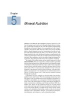
2. Select belt and cross section.Rotation speed of faster shaft n, rpm the cross section of V belt
is selected by the Figure
5000 based on the given
parameters:
3150 + Power P
+ Rotating speed n
A
2000
1250 B
C
800
D
500
E
315
200 3.15 5 8 12.5 20 31.5 50 80 125 200 400
2
Power P, kW
TS. Phan Cơng Bình 14-Mar-23
15
Sequence of calculation and design the belt drives
3. Parameters of the belt drive.
d1, d2 (mm) : Pitch circle diameters
a (mm) : Center distance
α1, α2 : Angle of wrap
TS. Phan Cơng Bình 14-Mar-23
16 14/3/2023
6
Sequence of calculation and design the belt drives
4. Select diameter of pulley.
Select diameter of
driving pulley 𝒅𝟏
according to Table
4.13
Standardized to
select 𝑑 (mm): 63,
71, 80, 90, 100,
112, 125, 140, 160,
180, 200, 224, 250,
280, 315, 335, 400,
450, 500, 630, 710,
800, 900, 1000, ...
Nên chọn 𝑑 ≈
1,2 𝑑 , chỉ khi
nào yêu cầu kích
thước thật nhỏ
gọn mới chọn
𝑑 =𝑑
TS. Phan Cơng Bình 14-Mar-23
17
Sequence of calculation and design the belt drives
4. Select diameter of pulley.
a) Validation velocity of the belt
v1 .d1.n1 v1< 25 m/s for V - belts
60.1000 v1< 40 m/s for Narrow V belts
Calculation and select pitch circle diameter of the driven pulley d2:
u n1 d2 d2 d2 d1.u
n2 d1 1 d1
Chọn 𝑑 𝑡ℎ𝑒𝑜 𝑑ã𝑦 𝑡𝑖ê𝑢 𝑐ℎ𝑢ẩ𝑛 𝑔ầ𝑛 𝑣ớ𝑖 𝑔𝑖á 𝑡𝑟ị 𝑡í𝑛ℎ 𝑡𝑜á𝑛 𝑛ℎấ𝑡
TS. Phan Cơng Bình 14-Mar-23
18
Sequence of calculation and design the belt drives
5. Length and center distance.
Assumed Centre distance (a):
u 1 2 3 4 5 >6
0.95d2 0.9d2 0.85d2
a 1.5d2 1.2d2 d2
0,55d1 d2 h a 2d1 d2
Select center distance as based on table and can be obtained by the formula
Length of belt (l):
Based on the assumed center distance as, the length of belt is obtained by
following Equation: d1 d2 d2 d1 2
l 2as 2 4a s
Then, the belt length is standardized and given in Table 4.13
TS. Phan Cơng Bình 14-Mar-23
19 14/3/2023
7
Sequence of calculation and design the belt drives
6. Determine center distance
Calculation exactly center distance (a):
Based on the selected length of belt, the center distance is re-defined by
where, 2 82
a
4
l d1 d2
2
d2 d1
2
TS. Phan Cơng Bình 14-Mar-23
20
Sequence of calculation and design the belt drives
7. Angle of wrap.
𝛼 = 𝜋 − 2𝛽 𝑟𝑎𝑑
𝛼 = 𝜋 + 2𝛽 (𝑟𝑎𝑑)
Condition: 𝛽 ≤ 10° ⇒ 𝛽 ≈ sin 𝛽 =
𝛼 = 𝜋− 𝑟𝑎𝑑 = 180° − . 57°
𝛼 =𝜋+ 𝑑 −𝑑 𝑟𝑎𝑑 = 180° + 𝑑 −𝑑 . 57°
𝑎 𝑎
Validation of the wrap angle: 𝛼 ≥ 120° for the V belt
𝛼 ≥ 150° for the Flat belt
TS. Phan Cơng Bình 14-Mar-23
21
Sequence of calculation and design the belt drives
8. Calculation the number of belt.
Number of belt is calculated by formula: (≤ 6)
z P1Kd
[P0 ]C ClCuCz
+ P1 (kW) Power of driving pulley 1 150...1800
+ P0 (kW) Power permit on Table 4.19 for V- belt
Table 4.20 for Flat belt
+ Kd: Coefficients of dynamic load Table 4.7
+ Cα: Coefficient of angle wrap’s effect Table 4.15
Or calculation according to formula: 1 0,0025(180 1) if
+ Cl: Coefficient of length’s effect Table 4.16
l: Real length of belt
l0: Experimental length of belt on Table 4.19 and 4.20
+ Cu: Coefficient of ratio’s effect Table 4.17
+ Cz: Coefficient of load’s effect Table 4.18
TS. Phan Cơng Bình 14-Mar-23
22 14/3/2023
8
TS. Phan Công Bình 14-Mar-23
23
Sequence of calculation and design the belt drives
8. Calculation the number of belt.
Table 4.15
α 180 170 160 150 140 130 120 110 100 90 80 70
Cα 1 0,98 0,95 0,92 0,89 0,86 0,82 0,78 0,73 0,68 0,62 0,56
Table 4.16
l/l0 0,5 0,6 0,8 1,0 1,2 1,4 1,6 1,8 2,0 2,4
Cl 0,86 0,89 0,95 1,0 1,04 1,07 1,10 1,13 1,15 1,20
Table 4.17
u 1 1,2 1,6 1,8 2,2 2,4 ≥3
1,07 1,11 1,12 1,13 1,135 1,14
Cu 1
Table 4.18
z 1 2-3 4-5 6
Cz 1 0,95 0,9 0,85
TS. Phan Cơng Bình 14-Mar-23
24
Sequence of calculation and design the belt drives
8. Calculation the number of belt.
Table 4.19 Value allowable power [P0] of V belt
Cross section Diameter of Velocity (m/s)
and laboratory driving pulley 3 5 10 15 20 25
length lo (mm) d1 (mm)
O 63 0,33 0,49 0,83 1,04 1,14
lo = 1320
90 0,46 0,64 1,17 1,54 1,8 1,88
112 0,48 0,75 1,33 1,78 2,12 2,3
112 0,7 1,08 1,85 2,4 2,73 2,85
A 125 0,78 1,17 2,0 2,75,2,9 3,08 3,26
lo = 1700
140 0,8 1,25 2,20 2,3,14 3,44 3,75
160 0,84 1,32 2,34 3,27 3,78 4,09
180 0,88 1,38 2,47 4,06 4,46
125 0,92 1,38 2,25 2,61 - -
lo = 2240 180 1,2 2,13 3,38 4,61 5,34 5,93
224 1,35 2,30 4,0 5,53 6,46 7,08
280 1,65 2,51 4,47 5,57 7,38 8,22
TS. Phan Cơng Bình 14-Mar-23
25 14/3/2023
9
Sequence of calculation and design the belt drives
8. Calculation the number of belt.
Table 4.19 Value allowable power [P0] of V belt
Cross section Diameter of Velocity (m/s)
and laboratory
length lo (mm) driving pulley 3 5 10 15 20 25
B d1 (mm) 6,28 -
lo = 3750 9,23 9,69
200 1,83 2,73 4,55 5,75 10,27 11
Г 11,33 12,27
lo = 6000 250 2,3 3,54 6,02 8 12,42 13,63
14,15 15,62
280 2,46 3,77 6,59 8,82
16,5 17,51
315 2,63 3,88 7,39 9,71 24,9 26,47
27,89 32,19
355 2,84 4,29 7,57 10,51 31,11 34,23
450 3,08 4,74 8,54 11,53
355 - 6,67 11,17 14,91
500 - 9,75 15,57 20,23
630 - 10,76 17,46 23,60
800 - 11,14 19,16 26,50
TS. Phan Công Bình 14-Mar-23
26
Sequence of calculation and design the belt drives
8. Calculation the number of belt.
Table 4.20 Value allowable power [P0] of V belt
Cross section Diameter of Velocity (m/s)
and laboratory driving pulley 5 10 15 20 25
length lo (mm) d1 (mm) 3
63 0,71 0,93 1,46 1,77 1,85 -
71 0,77 1,15 1,85 2,46 2,72 2,69
YO 90 0,93 1,46 2,74 3,74 4,23 4,52
lo = 1600
112 1,15 1,73 3,15 4,26 5,23 5,85
140 1,46 1,88 3,54 4,93 6,14 7
180 2,23 4 5,74 6,87 7,28
180 2 3,05 5,33 7,53 9,15 10,26
YA 220 2,12 3,14 5,77 7,93 9,77 11,15
lo = 2500
224 2,23 3,26 6,02 8,46 10,3 11,85
250 2,34 3,72 6,61 8,77 10,85 12,55
TS. Phan Cơng Bình 14-Mar-23
27
Sequence of calculation and design the belt drives
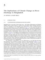
9. Sliding phenomenon of belt drive.
Sliding curve ε(ψ) – effect curve η(ψ).
Set coefficient of tension: Ft t
2F0 2. 0
TS. Phan Cơng Bình 14-Mar-23
28 14/3/2023
10
Sequence of calculation and design the belt drives
9. Sliding phenomenon of belt drive.
Elastic Sliding :
Cause of the belt is
elastic strain. The more
flaccid of belt, the more
stretched so sliding
increase
Slippery Sliding : AC. Sliding arc BC. Static arc
Cause of the belts chains is overload, tangential force Ft is higher than friction Fms,
The sliding slippery occurred at ACB arc on pulley
TS. Phan Cơng Bình 14-Mar-23
29
Sequence of calculation and design the belt drives
10. Tension in the belt
Tension in the belt:
Or Fr = 2.F0.sin(α1/2) 14-Mar-23
(Common Fr = ( 2 – 3)Ft
TS. Phan Cơng Bình
30
Sequence of calculation and design the belt drives
10. Tension in the belt
• Tangential force cause by T1:
• Tension of the side F1: F1 = F0 + Ft /2.
• Tension of the side F2: F2 = F0 – Ft /2.
According to Euler’s formula about friction,
We have: F1 = F2.efα .
Ft (e fα 1) Ft 2
F0 fα 1 fα
2 (e 1) 2 (e 1)
F0 Initial force is necessary for transmitting power P1 or torqueT1.
TS. Phan Cơng Bình 14-Mar-23
31 14/3/2023
11
Sequence of calculation and design the belt drives
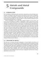
11. Stresses in belt.
Bending stress:
If belt material according Hook’s law: σu = E.ε
(E: Young module; ε Elongation)
Stress diagram: δ
ε=
𝑑
TS. Phan Công Bình 14-Mar-23
32
Sequence of calculation and design the belt drives
11. Stresses in belt.
Tensile stress:
Stress due to initial tension: 0 F0
Stress tension on driving side: A
Stress tension on driven side:
Stress due to centrifugal forces: 1 F1 0 t ; t Ft
A 2 A
2 F2 0 t
A 2
FV qm.v2 (condition v>20m/s)
V
AA
TS. Phan Cơng Bình 14-Mar-23
33
Exercise
Q.1
There is the flat belt drives with Power P1=6,5kW and the rotation speed of
the faster shaft n1=1420 rpm and the remained shaft n2=565 rpm. The
center distance a is 1800mm. The velocity of belt is from 14,5 m/s to 15,5
m/s. The pitch circle diameter of pulleys are standardized in the given
range: 160, 180, 200, 224, 250, 280, 315, 400, 450, 500, 560, 630, 710
(mm).
1) Determine diameter of driving pulley d1 and driven pulley d2?
2) Validate the wrap angle α1?
TS. Phan Công Bình 14-Mar-23
34 14/3/2023
12
Exercise
1) Determine diameter of driving pulley d1:
Solution 1: Based on velocity of belt
vmin πd1minn1 d1min 60000vmin 60000 14, 5 195,12mm
60000 πn1 3,14 1420
vmax πd1maxn1 d1max 60000vmax 60000 15, 5 208,57mm
60000 πn1 3,14 1420
Select d1 based on standard values: d1 = 200mm
Solution 2: Based on Savơrin formula
d1 (1100 1300) 3 P1 182, 64 215,85(mm)
n1
Select d1 based on standard values : d1 = 200mm
TS. Phan Cơng Bình 14-Mar-23
35
Exercise
1) Determine diameter of driven pulley d2:
u12 n1 d2 d2 n1 d1 502, 65mm
n2 d1 n2
Select d2 base on standard values : d2 = 500mm
2) Checking the condition of wrap angle α1:
α1 1800 d2 d1 570 1800 500 200 570 170,50 1500
a 1800
TS. Phan Công Bình 14-Mar-23
36
Exercise
Q2:
The flat belt drive includes the pulleys with pitch circle diameters
d1=150mm, d2=600mm. Width belt b=50mm and thickness = 6mm. The
friction coefficient between the pulley and belt is 0,32; Initial stress
0=2MPa. Angle of wrap 1=1600 and rotating speed n1=1000v/ph.
Determine center distance a of belt drives?
Determine initial tension F0 and tangential force Ft on driving pulley?
Calculating max power P1?
TS. Phan Cơng Bình 14-Mar-23
37 14/3/2023
13
Exercise
Determine center distance a of the belt drives :
𝑑 −𝑑
𝛼 = 180 − 57
𝑎
𝑎 = 57 𝑑 −𝑑 = 57 600 − 150 = 𝟏𝟐𝟖𝟐, 𝟓𝑚𝑚
180 − 160 20
Determine initial tension 𝐹 and tangential force 𝐹 on driving pulley :
• Cross-section: 𝐴 = 𝑏 ∗ 𝛿 = 50 ∗ 6 = 𝟑𝟎𝟎𝑚𝑚
• 𝐹 =A0= 300x2=600 N
tangential force Ft :
• Condition tension belt 2𝐹 : 𝑒 − 1 ≥ 𝐹 𝑒 + 1
2𝐹 𝑒 − 1 2 ∗ 600 ∗ 𝑒 , ∗ , − 1
𝐹= = = 𝟓𝟎𝟑, 𝟏𝑁
+1 𝑒 , ∗ , +1
𝑒
TS. Phan Cơng Bình 14-Mar-23
38
Exercise
Calculating max power P1 :
• Velocity on driving pulley:
𝑣= 𝑑 𝑛 3.14 ∗ 150 ∗ 1000
= = 𝟕, 𝟖𝟓(m/s)
60. 10 60. 10
• Power on the driving pulley:
𝑃= 𝐹 𝑣 503,1 ∗ 7,85
= = 𝟑, 𝟗𝟓𝑘𝑊
1000 1000
TS. Phan Cơng Bình 14-Mar-23
39
Exercise
Q3:
Flat belt drives has center distance a=1800mm, pulley diameter
d1=200mm, d2=600mm. Friction coefficient between pulley and belt
f=0,30; Power P1=6,5kW and rotating speed n1=1200rpm.
Determine and checking the condition of wrap angle α1?
Determine initial tension F0 to the belt chains disappear sliding
slippery
Replace the belt by the other type with the fiction coefficient f=0,35.
How the tangential force Ft is increasing?
TS. Phan Cơng Bình 14-Mar-23
40 14/3/2023
14
Exercise
1) Determine and validation the condition of wrap angle α1
α1 1800 d2 d1 570 1800 600 200 570 167,30 1500
a 1800
2) Determine initial tension F0 to satisfy the working basic condition
α1=167,30 = 2,92 rad
Ft 2T1 517,3N
d1
where, T1 9,55106 P1 9,55 106 6,5 51730 Nmm
n1 1200
Hence,
F (e fα1 1) 517,3 (e0,32,92 1)
F0 t2(e fα1 1) 2 (e0,32,92 1) 627, 7N
TS. Phan Cơng Bình 14-Mar-23
41
Exercise
3) How is the tangential force Ft change?
' 2F0 (e fα1 1) 2 627, 7 (e0,352,92 1)
Ft 591,04N
fα1 0,352,92 1)
(e 1) (e
The tangential force Ft increasing
Ft' 591,04 1,143
Ft 517,3
TS. Phan Cơng Bình 14-Mar-23
42
TS. Phan Cơng Bình 14-Mar-23