Chapter 4 Fundamental Of Component Design.pdf
Bạn đang xem bản rút gọn của tài liệu. Xem và tải ngay bản đầy đủ của tài liệu tại đây (2.7 MB, 20 trang )
15/9/2021
1
DEPARTMENT OF EDUCATION AND TRAINNING
HOCHIMINH CITY UNIVERSITY OF TECHNOLOGY
AND EDUCATION
THEORY OF MACHINE AND MACHINE
Chapter 4: DESIGN
FUNDAMENTAL OF COMPONENT DESIGN
15-Sep-21
2
Contents
I. Loads and stresses in
machine parts
II. Basic criteria of machine
part
III. Mechanical transmission
system and their principal
feature
TS. Phan Cơng Bình 15-Sep-21
1
15/9/2021
3
I. Loads and stresses in machine parts
1. Loads
- Load in mechanisms is the physical unit on mechanical system or component.
- Classification: Static load and dynamic load
Static load Dynamic load
TS. Phan Cơng Bình 15-Sep-21
4
I. Loads and stresses in machine parts
1. Loads
• 3 kinds of load:
Rated load: The longest or maximum effective load
Equivalent load: a constant value represented for dynamic load
Qtd QdnK E
Assumed load: applied to design machine parts
Ke: Coefficient depends on load mode
Qtt Qtd K tt K d K dk
Ktt: Coefficient considers nonuniform distribution
Kd: Coefficient of dynamic load
Kdk: Coefficient depends on working condition
TS. Phan Cơng Bình 15-Sep-21
2
15/9/2021
5
I. Loads and stresses in machine parts
2. Stress
- Stress is internal resistance due to external forces
2 Types of stress:
Static stress Dynamic stress 15-Sep-21
TS. Phan Cơng Bình
6 I. Loads and stresses in machine parts
2. Stress
- Stress cycle: The minimum time for the stress to return to original state
- 2 types of cycle stress:
Cycle stress stable over time
Cycle stress oscillated over time
- Amplitude stress: a max min
- Mean stress: 2
- Stress ratio:
m max min
2
r min
max
TS. Phan Cơng Bình 15-Sep-21
3
15/9/2021
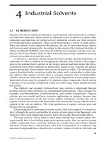
7 I. Loads and stresses in machine parts
2. Stress
σ
σa σmax σa σmax σmax = σmin
σa σm σa
σmax σm
σmax
σmin r = 0 r = +C σmin n
σm
r = -C
σmin
r = -1
a) b) c) d) e)
Symmetrical period asymmetrical period Closed circuit period asymmetrical period Constant stress
opposite sign same sign
TS. Phan Cơng Bình 15-Sep-21
8 I. Loads and stresses in machine parts
2. Stress
k(n) F [ ] c F [ c ] F [ ] F F [ F ] H [ H ]
A A Wo W
F: Force (N) and A: Cross-section (mm2)
W, Wo: The resistance moment (mm4)
TS. Phan Cơng Bình 15-Sep-21
4
15/9/2021
9 I. Loads and stresses in machine parts
2. Stress
TS. Phan Cơng Bình 15-Sep-21
10 I. Loads and stresses in machine parts
2. Stress
TS. Phan Cơng Bình Contact stress 15-Sep-21
5
15/9/2021
1
1
Contents
I. Loads and stresses in
machine parts
II. Basic criteria of machine
part
III. Mechanical drive
transmission system
TS. Phan Cơng Bình 15-Sep-21
12
II. Basic criteria of machine part
1. Strength
Definition: The ability of material to resist breaking .
2 types of destruction:
Destruction caused by exceeding working stress (overload)
Destruction caused by long-tern effects of changing stress value is
over the limit of ultimate strength
Calculate method: Static stress of element
Plasticity material: [ ] ch ; [ ] ch
[s] [s]
Brittle material: [ ] b ; [ ] b
ε: Coefficient of measurement [s]Ks [s]Ks
Ks: Coefficient of concentration static load
TS. Phan Cơng Bình 15-Sep-21
6
15/9/2021
13 II. Basic criteria of machine part
1. Strength
TS. Phan Cơng Bình 15-Sep-21
14
II. Basic criteria of machine part
1. Strength
Element has dynamic stress σa, σm= const. Calculation stress: [ ] lim KL
[s]K
KL: Life coefficient depends on N
β: coefficient of durable increase
Calculate cycle of operations element:
N > N0: Limited stress is limited long fatigue KL=1 N 60Lhn NLE Nk
[ ] r [s]: 1.5-2 safety coefficient
[s]K
N < N0: Limited stress is limited short fatigue
[ ] r KL,KL m N0
[s]K NLE
TS. Phan Công Bình 15-Sep-21
7
15/9/2021
15 II. Basic criteria of machine part
1. Strength
TS. Phan Cơng Bình 15-Sep-21
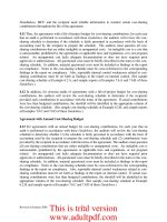
16 II. Basic criteria of machine part
1. Strength
TS. Phan Cơng Bình Curved of fatigue 15-Sep-21
8
15/9/2021
17
II. Basic criteria of machine part
2. Rigidity
Definition: The ability of material to resist deformation
Calculate: l Fal [l ]
Axial force: Long transposed EA
E: Modulus of elasticity (MPa)
A: Axial cross-section
L: Length of axis
Moment of deflection y [y]; [ ]
y: displacement
θ: Rotate angle Tl []
Moment of torsion GJ0
G: Modulus of elasticity
J0: Inertia moment
TS. Phan Cơng Bình 15-Sep-21
18
II. Basic criteria of machine part
3. Wear strength
Definition: The ability of element that working under time of limited wear
Calculate:
Limited pressure: Relationship between pressure and distance
Pm.S const
Condition: p ≤ [p]
4. Heating
During the working process, the machine will generate heat due to friction,
engine, ….
The harmful effects of heat:
Changing characteristic of material
Machinery parts will stick together
Reduce accuracy of machine because of thermal deformation
TS. Phan Cơng Bình 15-Sep-21
9
15/9/2021
19
II. Basic criteria of operating capacity of machine part
4. Heating
Cutting temperature generation
TS. Phan Cơng Bình 15-Sep-21
20
II. Basic criteria of operating capacity of machine part
5. Resistance vibration
𝐹𝑙𝑡 = 𝑐𝑦 e
ey
where,
l/2 l/2 l/2 Flt l/2
𝐹𝑙𝑡 = 𝑚𝑟𝜔 = 𝑚(𝑦 + 𝑒)𝜔
𝑚𝜔 𝑒 𝑒
𝑦(𝜔) = 𝑐 − 𝑚𝜔 − 1 = 𝑐
𝑚𝜔
at 𝜔 = 𝜔𝑛 = (natural frequency)
then 𝑦 → ∞ (𝑟𝑒𝑠𝑜𝑛𝑎𝑛𝑐𝑒)
𝑐 = 48𝐸𝐽 stiffness
𝑙
𝝎
Note: r𝐞𝐬𝐨𝐧𝐚𝐧𝐜𝐞 𝐟𝐫𝐞𝐪𝐮𝐞𝐧𝐜𝐲 ≈ (𝟎. 𝟕 ÷ 𝟏. 𝟐)
𝝎𝒏
TS. Phan Cơng Bình 15-Sep-21
10
15/9/2021
21
II. Basic criteria of operating capacity of machine part
5. Resistance vibration
TS. Phan Cơng Bình 15-Sep-21
22
Contents
I. Loads and stresses in
machine parts
II. Basic criteria of machine
part
III. Mechanical drive
transmission system
TS. Phan Cơng Bình 15-Sep-21
11
15/9/2021
23
1. Power III. Mechanical drive transmission
Ft
P Ftv (kW ) Ft: Tangential force (N) v
1000 v: Velocity (m/s)
2. Velocity n
• Velocity of driving pulley: v Dn (m / s) D T
60000
• Velocity of chain: v pzn (m / s) P
60000
• Rotating speed of pulley: n 60000v (rpm) D: Diameter (mm)
D
• Rotating speed of chain: n 60000v (rpm) n: Rotating speed (rpm)
zp p: Pitch of chain
• Angular velocity: 2 n (rad / s) z: Number of teeth in
60 sprockets
TS. Phan Cơng Bình 15-Sep-21
24
III. Mechanical drive transmission
3. Torque In T1 P1
Drive
• Given Power and rotation speed I x
n1
T1 9.55x10⁶ xP1 (Nmm) 12 PII
u12 nI PI
n1 nII
• Given tangential Force and diameter T2
T1 Ft d1 (Nmm) II P2 Out
2
n2 x X
driven
4. Transmission Ratio
• Belt drives, friction drives:
u12 d2
(1 )d1
• Gear drives, worm-gear drives, chain drives:
u12 z2
z1
TS. Phan Cơng Bình 15-Sep-21
12
15/9/2021
25
III. Mechanical drive transmission
5. Efficiency P2 P1 Pm
P1 P1
• Series: 1.2.3...n
• Parallel: 1 2 ... n
PI PII P Ftv (kW )
12 1000
u12 n1 n2 n1 n 6 0 0 0 0 v ( r p m )
n2 u12 D
TII=uɳTI T 9,55 106 P (Nmm)
n
TS. Phan Cơng Bình 15-Sep-21
26 III. Mechanical drive transmission
ESSAY
TS. Phan Cơng Bình 15-Sep-21
13
15/9/2021
27
III. Mechanical drive transmission
Pct nI x PI x Làm việc Plv (Ptđ)
Fv Tn nlv (III)
M I
nđc
nII x II x PII
ht d1 12 23 uht ud1 u12 u23
nt,o br ,o x,o unt ubr ux
TS. Phan Cơng Bình 15-Sep-21
28
III. Mechanical drive transmission
1. Determine the required power on the motor’s shaft
Based on diagram, the system includes 1 clutch, 1 pair of helical gear, 3
bearing roller gear and 1 chain drive
η ηnt ηbr ηol 3 ηx
where, the reference efficiencies are shown on the given Table
Pct Plv
η
2. Determine the preliminary speed of motor’s shaft
Based on diagram, the system includes 1 pair of helical gear and 1 chain drive
usb = uh x ux
where, the reference ratios are shown on the given Table (minimum values)
nsb = usb x nlv compared to 750; 1000; 1500 & 3000 (synchronous speed)
TS. Phan Cơng Bình 15-Sep-21
14
15/9/2021
29
III. Mechanical drive transmission
3. Transmission Ratios
utt nm ubr ux where, ubr is chosen in the givenTable ux utt
nlv ubr
1.0 1.25 1.6 2.0 2.5 3.15 4.0 5.0 6.3 8.0
Try to select ux based on the rated range
Nên chọn un (ud hoặc ux) theo tiêu chuẩn rồi kiểm tra sai số tỉ số truyền tổng thể
Check the tolerance of total ratio
u utt u compared to the required tolerance (4 5%)
utt
Nếu chọn un theo tiêu chuẩn mà khơng thỏa sai số tỉ số truyền thì dùng luôn
giá trị đã tính được sau khi chọn uh
TS. Phan Cơng Bình 15-Sep-21
30
Example
I
x
II x Làm việcx
III Tn
M
đc
Giving the parameter on the working shaft:
T = 425000 Nmm, n = 120 rpm
1. Motor specification
TS. Phan Cơng Bình 2. Transmission ratio distributions 15-Sep-21
15
15/9/2021
31
Motor selection
1. Determine the power of working shaft
6 Tlv nlv 425000 120
Tlv Plv 6 6 5,34(kW )
9,55.10 .Pt
nlv 9,55 10 9,55 10
The load is static: Pt = Plv = 5,34 kW
Based on diagram: 1 belt drive, 3 bearing roller, 1 pair of helical gear, 1 clutch
η ηd .ηol 3.ηbr .ηnt As shown on Table 2.3
ηd = 0,96 belt drive efficiency
0,96 0,993 0,97 0,9 0,81
Pct Pt 5,34 6.59 (kW ) ηol = 0,99 bearing efficiency
η 0,81 ηbr = 0,97 1 pair spur efficiency
ηnt = 0.9 clutch efficiency
TS. Phan Cơng Bình 15-Sep-21
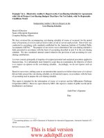
32
Table 2.3
Name Efficiency η
Closed Open
Spur gear drive 0,96 – 0,98 0,93 – 0,95
Bevel gear drive 0,95 – 0,97 0,92 – 0,94
Worm gear drive
- Self – locking 0,3 – 0,4 0,2 – 0,3
- Unself – locking with
0,7 – 0,75 0,9 – 0,93
z1 =1 0,75 – 0,82 0,7 – 0,88
z1 = 2 0,87 – 0,92 0,95 – 0,96
z1 = 4 0,95 – 0,96
Chain drives 0,9 – 0,96
Friction drives
Belt drives 0,99 – 0,995
Pair of rolling bearing 0,98 – 0,99
Pair of plain bearing
TS. Phan Cơng Bình 15-Sep-21
16
15/9/2021
33
Motor selection
4. Calculating the preliminary speed of motor
Preliminary ratio (based on Table 3.2) Gear Ratio
usb = uh x uđ Spur gear
= 1.6 x 2 (select minimum value) - 1 level gear box 1,6 – 8
- 2 level gear box 8 – 40
nsb = usb,.nlv,= 120x3.2 = 384 rpm Bevel gear box 1 – 6,3
nsb < 750 selection Motor~ 750 rpm - 1 speed gear box 8 – 30
- 2 speed gear box
Flat belt drive
Selection of motor (3 phases 380V-50Hz)
is satisfied by: - Simple 2 –5
4 –6
Pđc ≥ Pct = 6.59 kW - Tensioner 2–5
nđc ≥ nsb (~ 750 rpm) V belt drive 2 –5
Selection of electric power in Catalogue Chain drive 2 –4
Friction belt drive
TS. Phan Cơng Bình 15-Sep-21
34
Motor selection
Spec Motor M2QA16L8A
Power (kW) 7,5
Rotation speed(rpm) 720
TS/TN 2,1
TS. Phan Cơng Bình 15-Sep-21
17
15/9/2021
35
Distribution the transmission ratio
1. Ratio
utt nm 720 6 ubr ud Select ubr 2,5 ud utt 6 2, 4
nlv 120 ubr 2,5
1.0 1.25 1.6 2.0 2.5 3.15 4.0 5.0 6.3 8.0
Try to select ud =2,5 (based on the given rate range)
𝑢đ= 2; 2,24; 2,5; 2,8; 3,15; 3,56; 4; 4,5 & 5
Then, check the tolerance of total ratio
u utt u utt ubr ud 6 (2,5 2,5) 4,1% 4% not satisfied
utt u tt 6
Chọn ud theo tiêu chuẩn không thỏa thì thì phải thiết kế theo số liệu đã tính
ud=2,4
TS. Phan Cơng Bình 15-Sep-21
36
Distribution the transmission ratio
2. Rotation speed of shafts n1 ndc 720 300 rpm
Rotation speed of shaft I: ud 2,4
Rotation speed of shaft II: n2 n1 300 120rpm
ubr 2,5
Rotation speed of working shaft: nlv n2 120rpm
3. Calculating the power on shafts
Power on shaft II: P2 Plv 5,34 6,0 kW
ηnt .ηol 0,9x0,99
Power on shaft I: P1 P2 6 6,18 kW
ηbr .ηol 0,98x0,99
Power on motor’s shaft : Pdc P1 6,18 6,5 kW
ηd .ηol 0,96x0,99
TS. Phan Cơng Bình 15-Sep-21
18
15/9/2021
37
Distribution the transmission ratio
4. Calculation torque on shafts
9,55 10 .Pdc 9,55 10 6,56 6
Motor’s shaft: Tdc 86215 N.mm
ndc 720
Shaft I: T1 6 9,55 106 6,18 196730 N.mm
9,55 10 .P1
n1 300
Shaft II: T2 6 9,55 106 6,0 477500 N.mm
Working shaft :
9,55 10 .P2
n2 120
Tlv 6 9,55 106 5,34 424975 N.mm
9,55 10 .Plv
nlv 120
TS. Phan Cơng Bình 15-Sep-21
38 Distribution the transmission ratio
5. Results
Shaft Motor I II Working
Parameters 6,5 6,18 6,0 5,34
Motor (kW) 2,4 1
Ratio 2,5
Rotation speed (rpm) 720 120
Moment (N.mm) 86215 300 120 424975
196730 477500
TS. Phan Cơng Bình 15-Sep-21
19
15/9/2021
39
TS. Phan Cơng Bình 15-Sep-21
20