Báo cáo hóa học: " Research Article Building Flexible Manufacturing Systems Based on Peer-Its" doc
Bạn đang xem bản rút gọn của tài liệu. Xem và tải ngay bản đầy đủ của tài liệu tại đây (25.32 MB, 15 trang )
Hindawi Publishing Corporation
EURASIP Journal on Embedded Systems
Volume 2008, Article ID 267560, 15 pages
doi:10.1155/2008/267560
Research Article
Building Flexible Manufacturing Systems Based on Peer-Its
A. Ferscha,
1
M. Hechinger,
1
M. dos Santos Rocha,
2
R. Mayrhofer,
1
A. Zeidler,
2
A. Riener,
1
and M. Franz
2
1
Institute for Pervasive Computing, Johannes Kepler University Linz, Altenbergerstrasse 69, 4040 Linz, Austria
2
Siemens AG, Corporate Technology Software & Engineering, Architecture, CT SE 2, Otto-Hahn-Ring 6, 81730 Munich, Germany
Correspondence should be addressed to A. Ferscha,
Received 14 February 2007; Accepted 9 September 2007
Recommended by Valeriy Vyatkin
Peer-to-peer computing principles have started to pervade into mechanical control systems, inducing a paradigm shift from
centralized to autonomic control. We have developed a self-contained, miniaturized, universal and scalable peer-to-peer based
hardware-software system, the peer-it platform, to serve as astick-oncomputersolution to raise real-world artefacts like, for ex-
ample, machines, tools, or appliances towards technology-rich, autonomous, self-induced, and context-aware peers, operating as
spontaneously interacting ensembles. The peer-it platform integrates sensor, actuator, and wireless communication facilities on the
hardware level, with an object-oriented, component-based coordination framework at the software level, thus providing a generic
platform for sensing, computing, controlling, and communication on a large scale. The physical appearance of a peer-it supports
pinning it to real-world artefacts, while at the same time integrating those artefacts into a mobile ad hoc network of peers. Peer-it
networks thus represent ensembles of coordinated artefacts, exhibiting features of autonomy like self-management at the node level
and self-organization at the network level. We demonstrate how the peer-it system implements the desired flexibility in automated
manufacturing systems to react in the case of changes, whether intended or unexpectedly occuring. The peer-it system enables
machine flexibility in that it adapts production facilities to produce new types of products, or change the order of operation exe-
cuted on parts instantaneously. Secondly, it enables routing flexibility, that is, the ability to use multiple machines to spontaneously
perform the same operation on one part alternatively (to implement autonomic fault tolerance) or to absorb large-scale changes
in volume, capacity, or capability (to implement autonomic scalability).
Copyright © 2008 A. Ferscha et al. This is an open access article distributed under the Creative Commons Attribution License,
which permits unrestricted use, distribution, and reproduction in any medium, provided the original work is properly cited.
1. AUTONOMOUS SYSTEMS
Embedded systems become increasingly interconnected, di-
verse, and heterogeneous, reaching levels of complexity that
overwhelm even the most skilled administrators when in-
stalling, configuring, and maintaining such systems. One ap-
proach to cope with ever increasing system complexity is au-
tonomous computing, that is, to design systems able to man-
age themselves with no or little human interaction [1], so
as to improve overall systems dependability like efficiency,
availability, or fault tolerance. Autonomous computing sys-
tems are intended to have the ability to self-configure (each
device would automatically embed itself into the existing
landscape of devices without requiring a special installation
procedure or user intervention), to self-heal (systems should
be able to detect, diagnose, and recover from any damage),
to self-protect (the system should detect and protect itself
against injuries from accidents and other failures), to perfor-
mance monitor (the system should automatically distribute
tasks and subtasks to devices to maximize overall efficiency),
to dynamically a dapt to changed requirements, and so forth
[2].
Autonomous computing builds on allocation and deal-
location of shared resources and therefore, for example, for
optimization issues or preventing failures, needs negotiation
among an ensemble of distributed computers (peers) [3].
Typically, the peers making up an autonomous computing
system are geographically dislocated, and they often are het-
erogeneous in hardware and software, thus in function and
capability. The interplay of peers within the ensemble, seen
from the services offered, aims at exhibiting the character-
istics of autonomous computing, namely, self-monitoring,
self-organization, self-healing, and so forth.
Within the domain of flexible manufacturing systems
(FMSs), heterogeneous types of computer controlled ma-
chines (welding robots, drill machines, CNC machine tools,
conveyor belt, automated guided vehicle, etc.) are mixed with
purely mechanical production systems. To accomplish the
2 EURASIP Journal on Embedded Systems
management challenges for such types of systems, more au-
tonomous, self-induced, and spatially aware artefact com-
munication principles are needed, not necessarily aiming at
replacing traditional architectures but at enhancing the exist-
ing production systems towards reaching satisfactory levels
of autonomic behavior (self-organization, self-healing, self-
protection, self-reconfiguration, etc.).
1.1. From P2P to autonomous systems: related work
Peer-to-peer (P2P) systems are the consequence of a tech-
nological trend towards a more distributed, decentralized,
and dynamic computing paradigm. With an increasing num-
ber of miniaturized electronic appliances and their rising
functionality, the management of such systems becomes an
important and challenging issue. Self-adaptation and self-
configuration of devices according to their environment and
activities are a frequently proposed solution.
An early consideration of miniaturized computing plat-
forms spatially arranged on a pin board is “Pushpin com-
puting” [4]. Coin-sized computing elements (“Pushpins”)
are placed on the board to form an ensemble of peers, able
to communicate based on capacitive coupling via layered
sheets in the board, or wirelessly via infrared connections. A
similar approach is Pin&Play [5, 6]. Here, the “pin” devices
are sticked onto conductive wallpaper (called “the surface”),
with that being attached to power supply and the communi-
cation network. Pin devices can be freely placed even within
the surface, again forming an ensemble of peers.
The idea of attaching computing and communication
technologies in miniaturized form onto everyday objects,
raising them to peers or nodes of an implicit wireless sen-
sor network, is consequently implemented with Smart-Its
[7–9]. Smart-Its integrate sensors and communication ca-
pabilities on small, embedded devices, while the computa-
tion power (device control, application- specific processing,
communication with other devices, etc.) is hosted in de-
vices called “core units”. Implicit and explicit connections
of Smart-It equipped artefacts in vicinity allow for the im-
plementation of collectively aware peer ensembles. Cooper-
ative interation among peer-it tagged artefacts is exempli-
fied by chemical containers [10, 11], and due to the embed-
ded domain knowledge, perceptual intelligence and cooper-
ative rule-based reasoning are referred to as one of the first
systems with “intelligence” (defined in an individual peer
rule base and specified by the so-called first-order predicate
logic (horn clauses)). TEAs, context-aware modules [12],
have been proposed as peer systems which integrate multiple
sensors for context-aware peer behavior in a self-contained
device (mobile phones). The context information (i.e., in-
formation describing the situation of a peer) is derived from
raw sensor data, so that situations like in-hand, in-pocket, or
outdoors can be identified.
In the domain and for the purpose of supporting man-
ufacturing systems, a “holonic” system architecture was pro-
posed [13] built on top of three types of basic abstractions,
the so-called “holons”. Order holons, product holons, and
resource holons are embedded into the manufacturing con-
trol process, each with its role and responsibility like plan-
ning, scheduling, resource management, and logistics. The
holonic manufacturing concept was proposed as distributed
control paradigm to cope with the problems of manufac-
turing systems prone to frequent changes, unforeseeable dy-
namics, and disturbances. A whole branch of system archi-
tectures [14] has emerged since then [15], combining and
integrating the rich body of knowledge of agent-based sys-
tems into the domain of industrial manufacturing [16].
The “spatial computing” approach [17, 18] addresses
self-organization and adaptation with respect to the distri-
bution of computing elements (peers) in abstract or physical
space. A software framework, the TOTA middleware [19],
implements spatial views to services offered by dispersed
peers. The SIRENA [20] framework based on open standards
offers an infrastructure for high-level communication at the
sensor-actuator level with plug-and-play configuration. Au-
tonomous computing systems can be implemented in a tech-
nology neutral (regarding OS, programming language, net-
work protocols, etc.) style according to the P2P paradigm.
Besides these,a variety of other P2P frameworks have
evolved, in one way or another, abstracting the access to
shared resources, while distributing services. The application
development process of P2P applications within such frame-
works is eased by the provision of APIs to those services, but
P2P applications always have to be developed “from scratch”.
To bridge the architectural gap between such P2P applica-
tions and P2P frameworks, design patterns have been pro-
posed as an organizational schema for P2P-based software
systems [21]. A pattern-based software development pro-
cessisadvocatedin[22] and demonstrated for both func-
tional and topological P2P patterns. Developing P2P systems
within this approach simply means to choose and instantiate
from a collection of patterns.
Developing and managing complex P2P systems, even
with the support of frameworks, have grown costly and
prone to error, thus calling for mechanisms of self-
management of systems [23]. Traditional instructive systems
[24] with their passive, deterministic, context-free, and pre-
programmednaturearesuggestedtobereplacedbyau-
tonomous computing systems,whichareactiveinnatureand
implement nondeterministic, context-dependent, and adap-
tive behaviors. An autonomous computing system is suggested
to be one which autonomously and intelligently carries out
activities in a goal-driven style. An industrially inspired man-
ifesto [25]of“autonomic system”—in this case—identifies
the following constitutive characteristics.
(i) Self-awareness: an autonomic system exists at multi-
ple levels and is heavily interconnected with other sys-
tems/devices. It has to know details about its compo-
nents as well as the status of all other connected de-
vices.
(ii) Self-configuration: the system must configure itself
automatically, even in unforeseen and unpredictable
conditions.
(iii) Self-optimizing: an autonomic system permanently
monitors its system state and tunes its components to
increase overall system performance, throughput, and
efficiency.
A. Ferscha et al. 3
(iv) Self-healing: the system must be able to recover from
failures of its parts.
(v) Self-protection: the system has to monitor its (software)
components towards attacks to guarantee system in-
tegrity (security issue).
(vi) Context-awareness: an autonomic system needs to
know its environment and reacts accordingly. Adapt-
ing to the environment and interacting with surround-
ing systems are a highly dynamic process.
(vii) Self-management: an autonomic system must not be
used in a hermetic environment, but it has to be uni-
versal in that it implements open standards and adapts
to changed communication protocols, neighborhood,
and so forth.
This work aims at a universal autonomous computing
system addressing the above characteristics, but with a rad-
ically distributed approach. A stick-on computer solution
is proposed, implementing the so-called self-characteristics
based on the opportunistic interaction among distributed,
mobile, and heterogeneous peers, in the absence of global
knowledge and naming conventions. The work is struc-
tured as follows. Section 2 gives an introduction to the
peer-it system, a hardware-software stick-on solution to ad-
vance “dumb” real-world artefacts towards context-aware
autonomic peers. The term “peer-it” thereby is used as
and deduced from the well-known sticky note “post-it”.
Section 2.1 gives technical details on the peer-it hardware, in-
cluding an architecture overview and technical specifications.
Section 2.2 introduces the peer-it coordination framework,
the software solution responsible for profile-based, context-
aware, spontaneous interaction. The capabilities of the peer-
it system are demonstrated within a flexible manufacturing
system (FMS) setting, outlined in Section 3, starting with a
real-world manufacturing scenario and identifying its most
important capabilities and functionalities like self-routing,
checkpointing, and fault tolerance; a car producing FMS in-
volving mobile and context-aware peers is developed step
by step. Conclusions and a prospect to our future work are
drawn in the closing section (Section 4).
2. THE PEER-IT SYSTEM: A STICK-ON
AUTONOMIC SYSTEM SOLUTION
Miniaturized embedded systems are pervading at large scale
into everyday objects such as appliances, and environments
like offices, homes, and cars. This is particularly true for in-
dustrial and, therein, flexible manufacturing systems. Flex-
ible manufacturing systems (or parts of them, then called
flexible manufacturing cells) have gained incredible growth
over the past years, leaving behind low-technology manu-
facturing systems. The opportunities of an operative and se-
mantically meaningful interplay of these systems are decreas-
ing, widening the gap between technological generations of
machines. In order to bridge this gap, both from an inter-
operability as well as a self-organizing viewpoint, we pro-
pose a stick-on sensing, computing, and communication so-
lution for machinery of both high-tech as well as low-tech
nature. The driving motivation is to attach a universal fully
autonomous computing platform operated under an open
standard, self-configuring software framework, onto arbi-
trary real-world artefacts, raising by that attachment that
artefact to an “intelligent peer”, and simultaneously weaving
it into a wirelessly networked, spontaneously interacting en-
semble of peers forming the autonomous system.
Besides the requirements of a peer being a self-con-
tained, “all-in-one”, fully autonomous, sensor-actuator-com-
munication system on the hardware side, associated with a
corresponding coordination software, also the ability to self-
manage and self-organize was a guiding principle when de-
veloping the peer-it system. While self-management stands
for the ability of single peer (e.g., a manufacturing machine
or transport vehicle in the FMS domain) to describe itself, to
select, and to use adequate sensors for getting a global and
all-embracing picture of the surrounding environment, self-
organizing stands for the ability of a group of possibly hetero-
geneous peers to establish a situative network based on inter-
est, purpose, or goal, and to negotiate and fulfill a group goal.
Self-management thus relates to individual peers and con-
cerns adaptation to changing individual goals and conditions
at runtime, while self-organization relates to peer ensembles
and concerns adaptation in order to meet group goals.
The peer-it system is made up of two principal compo-
nents: (i) the peer-it platform on the hardware side, and (ii)
the peer-it framework on the software side.
2.1. The peer-it hardware platform
Technically, the peer-it platform is an “all-in-one” sensor-
actuator-communication hardware consisting of the execu-
tion platform (CPU, memory, standard interfaces), a sensor
array, and a collection of actuators. Wireless communication
(based on protocols IEEE 802.11 and IEEE 802.15) serves
to support communication in the nearby proximity. Sensors
are dedicated to collect data characterizing the situation of
a peer with respect to environmental conditions (like tem-
perature, light, humidity, noise, time, place, etc.). Actuators
respond to the control triggers resulting from the application
into the mechanical means of the respective peer. Communi-
cation among peer-its is based on the concept of proximity
detection and other mechanisms implemented in the peer-it
coordination framework (see Section 2.2).
With the aim of delivering sufficient computation power
as well as independent memory (which provides an oppor-
tunity of booting the operating system) and extendable in-
terfaces for I/O, we have selected the following components
for the prototypical peer-it platform. The specification can be
tailored in several dimensions, especially with regard to size
and computation power. Ideally, for the future, we envision
to see faster peer-its with a smaller form factor than today.
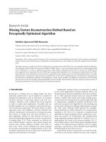
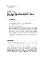
The basic building blocks of a peer-it system are the stick-on
computer equipped with the stick-on networking stack and
the matching stick-on software suite for interconnectivity
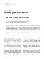
(see Figure 2). A peer-it system as used in the experimental
setting consists of PC104/+ board “SECO M570”, equipped
with a VIA Eden x86 compatible CPU (300 MHz, 1 GHz),
PCI bus, ISA bus (PC104/+ connector), 64 MB RAM, and
128 MB nonvolatile memory on a compact flash card for
4 EURASIP Journal on Embedded Systems
WE
N
S
Keyboard
Mouse
VGA
VIA Eden x86 CPU
PC104/+ SECO M570
RAM CF-card
PCI bus ISA bus
Peer-it
coordination
framework
USB1.1
Port 1
10/100
ethernet
COM
Port 1
USB1.1
Port 2
Netgear
MA111
WLAN
TCP/IP
Inside tech.
reader
RFID
Acer
BTCSR
Blue-
tooth
···
Communication
+12 V
Control
display
Pressure
valve
Switching
relais
Step
motor
Actuators
···
Stick-on computer
Sensors
···
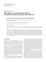
Figure 1: The peer-it platform architecture.
(a)
(b) (c)
Figure 2: The final peer-it hardware platform.
the peer-it software. For I/O, the board is equipped with
2 USB 1.1 ports, 10/100 Mbit Ethernet interface, parallel
and two serial ports, dual-channel audio, microphone and
corresponding line-out connectors, integrated 3D graphics
(VGA D- SUB15), and PS/2 keyboard and mouse connec-
tors.EachpeerisequippedwithanRFIDreader(“PicoTag
family”) from Inside Technologies for passive RFID tags, op-
erating at 13.56 MHz, and a tag storage capacity of either 640
bits or 2KB. For wireless interpeer, communication WLAN
(IEEE802.11b via USB-WLAN stick “Netgear MA111”) and
Bluetooth (IEEE802.15 Bluetooth 1.1 Class 2 with USB don-
gle “Acer BTCSR”) are used. The operating system is a mod-
ified Debian GNU/Linux 3.0 (woody) system with adjusted
2.4.26 kernel and adapted boot system having read-only op-
erating system (easily manageable, configurable, and updat-
able because of using an FAT file system with Linux as image-
file and XML-configuration via a windows client). A Black-
down Java 1.3.1 is running on top of the OS as environment
for peer-it applications. The typical power consumption of
one device is 7.5 watts (running on a clock rate of 400 MHz).
On the macrolevel, a comparable approach to implement
autonomous systems based on a stick-on principle has been
followed in the Smart-it project [8], where a communicating
sensor-actuator hardware platform (17
× 25 × 15mm) has
been developed. “Smart-Its Friends” have been introduced as
a proof of the concept of establishing qualitative relations and
selective connections among smart artefacts. Later, “Smart-
Its” have advanced to self-contained, miniaturized, stick-on
A. Ferscha et al. 5
Monitoring peer
Product peer
Tr an spor t pee r
Processing peer
Machine
control
Processing
program
FMS entity
applications
Profile
service
Peer
self-description
Bundle
repository
and exchange
Self configuration
policies
Ports service
(“Ad-hoc RMI”)
PML
integration
Bundle
management
Peer-it
framework
Peer service and object peer handling
Security support
TCP/IP
ZigBee
Bluetooth RFID Barcode
Transport Proximity Object identification
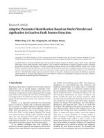
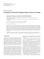
Figure 3: Peer-it software architecture.
computers at the level of 8-bit microcontrollers and 125 Kbps
communication [26]. Our peer-it stick-on computer raises
some of the concepts of Smart-Its to the microlevel.
2.2. The peer-it software framework
The peer-it framework is designed as a development base
for applications in autonomous system scenarios. It pro-
vides means for discovering other peers which are currently
within communication range and/or spatial proximity, based
on peers properties, interest, and intent expressed in the
so-called peer “profile”, encoded in the peer-it markup lan-
guage PeerML (an XML dialect). Profiles may not only con-
tain “static” definitions,but the coordination process can be
contextualized by adding context definitions to the profile as
well. This profile is carried along with each peer and ana-
lyzed with respect to the degree of matching with the profiles
of surrounding peers. The result of this profile matching, a
mathematical analysis of the semistructured profile data, is a
single value expressing the similarity or dissimilarity among
profiles. Each peer performs the process of profile matching
on its own, thus no centralized instance for matching profiles
is required. The peer-it framework operates fully decentral-
ized; it does not rely on any infrastructure for communica-
tion nor for coordination between peers.
2.2.1. The peer-it OSGi layered service bundle hierarchy
The peer-it software framework is built on top of an open
object-oriented component model, OSGi [27], and it is or-
ganized into several layered (OSGi) bundles (see Figure 4).
Bundles in the lower layers provide a service interface for
bundles in the upper layers. The OSCAR implementation
[28] of OSGi is used as a container; however, containers
like Apacke Felix [29] and Equinox [30] have been adopted
as well. Figure 3 depicts the overall bundle structure of the
framework. Basically, there are some core components and
some optional components that support the framework with
various functionalities. The core components of the frame-
work are (i) transport bundles in the transport layer, (ii) the
peer service, (iii) the ports service, and (iv) the profile ser-
vice.
Bundles in the transport layer are responsible for com-
munication with other peers. The transport layer defines
an interface with functionality for discovering peers and for
communication with remote devices. It is possible to (simul-
taneously) use different communication technologies such as
TCP/IP or Bluetooth. The interchangeability of the commu-
nication technology is an important feature since it allows to
use the framework on a wider range of devices. The main task
of the transport layer is to abstract communication from the
used technology, so that the peer layer residing on top of the
transport layer can easily utilize different transport technolo-
gies. To use a particular communication technology, a trans-
port bundle implementing the interface of the transport layer
must be implemented. By now, transport bundles for TCP/IP
and JXTA [31] exist; it is planned to add additional transport
bundles for communication technologies such as Bluetooth
or IrDA. The main objectives of a transport bundle are send-
ing and receiving advertisements in order to discover devices
(in cooperation with the peer service) and to send and receive
data to/from other devices.
Peer service
The peer service implements the ad hoc core functional-
ity for each peer running the framework. It is responsible
for (i) the communication technology-independent discov-
ery and communication with other peers utilizing transport
bundles, (ii) limiting communication range to peers within
spatial proximity using proximity bundles, (iii) securing
6 EURASIP Journal on Embedded Systems
Application layer
Profile layer
Peer layer
Tr an sp or t l ay er
Application layer
Profile layer
Peer layer
Tr an sp or t l ay er
WLAN
Bluetooth
Ethernet
Figure 4: The peer-it coordination framework layer structure.
communication utilizing the security support, and for (iv)
the transparent integration of passive objects as if they were
ordinary peers with processing capabilities (“object peer han-
dling”). To discover peers, the peer service publishes adver-
tisements which are small data packets describing the peer
very rudimentarily (basically, its ID and how to communi-
cate with it). To discover the absence of a peer, the peer ser-
vice utilizes individual timeout values in its advertisements.
Whenever no advertisement of a peer is received for longer
than the timeout specified in the last received advertisement,
the corresponding peer is considered as being no longer
present.
In various scenarios, ad hoc interaction should be lim-
ited to devices within a certain spatial proximity. The peer-it
framework provides basic functionality for limiting the in-
teraction to such a proximity. It does this by using a sim-
ple proximity sensor which is capable of sensing if an appro-
priate ID (such as a Bluetooth MAC address) is within the
range of the proximity sensor. Currently, the implementation
defines the proximity range of a peer by the used technol-
ogy (such as Bluetooth). However, we are currently working
on a more sophisticated model, which allows to define arbi-
trary complex geometric shapes for limiting communication
to spatial proximity.
Object peer handling denotes the capability of the frame-
work to integrate devices with limited means for commu-
nication, processing, and/or storage as peers (called object
peers). The only requirement of an object peer is that it must
provide means for identifying itself by an ordinary peer us-
ing the object identification layer (which again allows to use
several object identification bundles at the same time). We
are currently using RFID as technology for identifying ob-
ject peers. However, barcode, for example, could also be in-
tegrated as technology for object peers. The peer service pro-
vides bundles on top of its transparent access to such object
peers, as if they were ordinary peers. This is achieved us-
ing a proxy that interacts on behalf of the object peer. Each
peer can declare itself to be a proxy for objects, which is then
announced in the advertisement of the corresponding peer.
Upon identifying an object in the environment, the peer ser-
vice looks for a currently available peer that declared a proxy
for it. If such a proxy is found, the object is reported as a new
peer and subsequent messages to the object peer are rerouted
to the proxy peer. Additionally, a handler representing the ap-
plication of the object peer itself is activated at the proxy. For
active interaction (e.g., method invocations initiated by the
object peer), the handler utilizes the framework on the proxy
as ordinary applications do. We call this form of discovery
and interaction with object peers synchronous since both,
the object and the proxy, must be available at the same time.
On the other side, it is also possible to store identified objects
for later interaction with a possibly later available proxy. In
that asynchronous case, whenever a new ordinary peer be-
comes available, the peer service looks for previously found
objects (which do not require to be in range then) for which
the new ordinary peer declares itself to be proxy. Thus, inter-
action with the object peer can be conducted even if the ob-
ject itself is no longer in range but the proxy is. Such an asyn-
chronous interaction can be, for example, useful for scenar-
ios where a peer “discovers” objects (e.g., posters) in the en-
vironment, and the interaction with them is still meaningful
later on. The mode for object peer handling (synchronous or
asynchronous) can be adjusted for each individual object and
is mainly determined by the application scenario. Moreover,
we have planned to implement means to hand over the proxy
functionality from one peer to another at runtime in order
to increase the availability of proxies in dynamic scenarios.
Regarding security concerns, we have developed means for
handling the declaration of becoming a proxy for an object
which is presented in [32].
Ports service
The ports service (also called “ad hoc RMI”) on top of the
peer service provides means for discovery of services and in-
vocation of methods on remote peers. This service allows for
convenient interaction between applications on top of the
framework by method invocations instead of message-based
interaction. Details regarding the ports service can be found
in [33].
Profile service
The profile layer is responsible for “contextualizing” the pro-
files of peers attempting a similarity analysis of their proper-
ties, interests, or intent. Sensors embedded in a peer-it con-
tinuously collect sensor data, from which context informa-
tion is abstracted (see Figure 5). In a first step, interest spec-
ifications (roles) are exchanged among peers, thus allowing
for a fast and accurate peer identification and ensemble mem-
bership verification. In a second step, full length PeerML pro-
files are exchanged. Context transcoding and personalization
of profiles are induced right before the similarity analysis is
conducted, thus implementing situative interactions among
peers. Recent extensions of the peer-it coordination frame-
work offer the possibility of peer-to-peer communication
based on their “zones of influence”, described as geometri-
cal properties of the focus and nimbus of a certain peer (see
[22, 34, 35]).
The other bundles of the peer-it framework are described
in brief as follows.
The PML integration bundle can be used to automati-
cally integrate product-markup-language content (see also
A. Ferscha et al. 7
Profile layer Profile layer
Sensors
Time
Location
Te m p e r a t u r e
Brightness
Sensors
Time
Location
Te m p e r a t u r e
Brightness
Context
Context
Figure 5: Context-sensitive profile matching.
[36]) into the self-description of peers. Based on identified
objects (using the object identification layer), this compo-
nent fetches PML content from an EPC information service
(PML server) or a static file as information source and adds
it to the self-description of the peer. The component bun-
dle repository and exchange allow to exchange OSGi bun-
dles between peers. This functionality is used by the FMS
presented later in this document in order to transfer pro-
cessing specifications (which are implemented as bundles)
between peers. The self-configuration component allows to
configure various aspects of the framework and parts of the
self-description provided by the profile service semiautomat-
ically using event-condition-action rules. The security sup-
port bundle provides means for authentication of peers and
encryption of data transferred between peers. Finally, the
bundle management component provides a user interface for
lifecycle management of a peer’s bundles.
With a peer-it ability of self-description in its PeerML
profile, the framework supports managing applications not
only by context-independent properties like their spatial
proximity, but also by the examination of context-aware at-
tributes with according reactions, for example, by the ex-
ecution of different applications regarding the actual envi-
ronment properties collected by sensors. With compositional
context, we follow an approach of managing situational in-
formation by mobile peer-it computers fully autonomously.
Context constraints can be created by all possible set oper-
ations on geometrical objects, for example, intersection or
union. If peer-its are equipped with appropriate sensor tech-
nology, context constraints can be evaluated independently
at runtime—with the result of enabling the execution of
context-aware software—(see left-hand side of Figure 4). The
process of exchanging roles or profiles is well established as
a one-stage solution, independent of context conditions (in
that kind, these XML data containing the entities attributes
are shared and matched, and according to the result, actions
are invoked). The peer-it coordination framework extends
this concept by offering capabilities for a multilevel exchange
of profiles with the advantage of a fast and efficient identi-
fication whether the concerned peer needs further elaborate
analysis or not. Only in the case where the matching in the
higher level is fulfilled, a more fine, grained, complex analy-
sis will be applied on involved peers.
3. BUILDING FLEXIBLE
MANUFACTURING SYSTEMS
Modern FMSs or assembly facilities are made up of pro-
grammable machines (welding robots, CNC machine tools,
etc.), each of which owns control system (executing
controller-specific programs written in special-purpose lan-
guages to perform preprogrammed manufacturing steps),
and they are interconnected by automatic material transport
systems (conveyer belts or computer-controlled vehicle sys-
tems). Ideally, the sum of all manufacturing steps leads to a
completely manufactured item.
In spite of being equipped with wireless communica-
tion technologies (e.g., WLAN), most FMSs are still built as
client/server systems with central control. While these cen-
tralized manufacturing systems are well investigated and op-
timized today, they exhibit severe disadvantages like single
points of failures, high configuration and maintenance ef-
forts, and limited flexibility. Service-oriented architectures
partly address these shortcomings, by running only that sub-
set of actually required services on each manufacturing ele-
ment [37], but higher levels of flexibility are demanded. We
identify [38](i)production flexibility, that is, the ability of
an FMS to manufacture different parts without the necessity
of major retooling and changeovers, (ii) product lifecycle flex-
ibility as the degree to which an FMS can change from an
older to a newer product line or revision, and (iii) utilization
flexibility as the ability to change a production schedule, to
modify parts, or to handle multiple parts at production time
(e.g., relocate the manufacturing of a product to machine “B”
after machine “A” has failed).
3.1. Peer-it technology in FMS
Applying peer-it technology in the domain of FMS is moti-
vated by the potentials of gain in the following respects.
8 EURASIP Journal on Embedded Systems
Flexibility
Peer-to-peer approaches are extensively used in heteroge-
neous system environments with multiple operating sys-
tems. Especially environments with multiple operating sys-
tems, different hardware platforms, or frequently changing
requirements on functionality can greatly take advantage of
autonomous system design. In this area, our peer-it approach
allows for maximum flexibility with respect to OS, CPU-
type, or sensor/actuator combinations. Also, the use of the
Java programming language brings additional flexibility.
Autonomy
Every device in an application based on the peer-it platform
is in principle fully autonomic. As a consequence, the soft-
ware running on a peer is self-contained, and peer-to-peer
direct communication can be used to self-organize the sys-
tem behavior together with other entities. By modifying the
respective autonomous peers, the system can easily be ex-
tended or modified. Applied extensively, no central control
unit is necessary, removing a potential bottleneck and single
point of failure, in spite of being possible.
Scalability
Because of the flat and decentralized structure of the peer-
to-peer overlay network, the system scales more easily than a
centralized solution.
Fault tolerance and self-healing
Since it is a basic property in peer-to-peer systems, these ser-
vicesaswellasdataareusuallyredundant;faulttoleranceis
provided automatically (if one of the peers gets unavailable
for any reason, other peers reconfigure themselves automat-
ically and then offer the requested service). Additionally, an
application designed to be aware of the underlying system
properties can provide additional self-healing mechanisms,
like redistribution of work packages to other machines or
rerouting in case of failures.
Self-configuration
While in traditional client/server architectures each client
had to be aware about where it can find a specific service
or information, in autonomous peer systems this is usu-
ally not required. A typical autonomous system can auto-
matically find information or services needed by invoking
appropriate search queries. Moreover, peer-to-peer systems
can completely eliminate the need for basic configuration of
client/software and networking.
There are many well-engineered and established methods
for optimizing schedules, routes, or resource management,
which are still (at least partly) applicable in a P2P-based
FMS. Instead of further optimizing existing systems, we fo-
cus on taking advantage of autonomous peer technology in
the manufacturing domain. Although in the beginning the
optimizations of a centralized approach seem to be superior,
we hope to see in the future two developments. First, many
centralized algorithms can be translated into a decentralized
variety without losing their efficiency. And second, new ap-
proaches for decentralized optimization show their poten-
tial advantages, for example, in genetic programming. Ge-
netic algorithms are inherently autonomously organized and
partly have shown results better than their centralized coun-
terparts. Therefore, we see autonomous peer systems as an
important enabling technology in the FMS domain.
To demonstrate the different aspects of APS, we created
a demonstrator scenario where the different classes of actors
in FMS scenarios are reflected in separate “peers,” each taking
over a particular role within an FMS or FMC, respectively.
3.2. A table-top peer-it-based FMS demonstrator
To demonstrate peer-it technology as a proof of concept
for FMS, we have developed a table-top scenario rigorously
mapping a real FMS system into “Lego-world” model. Our
demonstrator FMS basically consists of the system compo-
nents which one would encounter also in the realm of manu-
facturing. Each of the elements in the table-top FMS is peer-it
enabled (for details, see [39]) and represents an FMS peer in
one of the following characteristic roles.
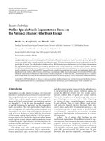
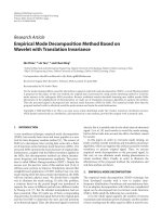
Transport peer
In an FMS, products are usually transported using an auto-
mated guided vehicle (AGV); see left-hand side on the lower
row of Figure 6. Automated guided vehicle systems are one
of the most dynamic research areas in production systems.
With increasing flexibility and the necessity of workload of
the overall production system of almost 100%, requirements
on AGVs increase massively and are heading towards fully
autonomous machines and systems. In the table-top FMS
scenario, the transport peer embodies such an autonomic
transport vehicle. It autonomously carries artefacts (denoted
as manufacturing goods) from and to machines. Upon plac-
ing such an artefact onto the transport peer, it automatically
detects the type of artefact (read its profile) and hence knows
which processing steps have to be performed on the manu-
facturing goods. The transport peer starts moving and car-
ries the artefact to the corresponding machine (processing
peer), which has the capability to process the first produc-
tion step in its checklist.
Processing peer
As mentioned earlier, work or manufacturing cells in FMS
consist of objects like CNC machines or welding robots (see
center image on second row of Figure 6)toperformsubtasks
in the production of a manufacturing good (product peer).
Depending upon kind and function, a machine (referred
to as processing peers in our FMS demonstrator scenario)
canperformvariousoperationsonawork-in-progressprod-
uct. Individual capabilities of processing peers are stored in
their PeerML profile, which is distributed to all peers in spa-
tial proximity. Processing steps are implemented as OSGi
bundles which can be lifecycle-managed at runtime by the
A. Ferscha et al. 9
(a) (b) (c)
(d) (e) (f)
Figure 6: Peer-it building blocks in the table-top (first row) and real-world scenarios (second row).
processing peer. The processing peer provides means for
starting and stoping these processing bundles as required.
Additionally, since processing steps are self-contained OSGi
bundles, they can be transferred between peers on demand
utilizing the bundle repository and exchange component. Af-
ter the transport peer has delivered an artefact (product peer)
to the processing peer, the next processing step which is re-
quired for the specific artefact is determined and started. Af-
ter the processing step is finished, the processing peer calls
the transport peer for pickup again.
Product peer
The manufacturing goods processed in a real FMS (see right-
hand side on lower row of Figure 6) are represented in the
table-top FMS by “product peers” (artifacts); they are the
goods being processed (e.g., a car, an engine, etc.), and they
typically require several different manufacturing processes.
In reality, artefacts are transported to the processing ma-
chines by an automated guided vehicle (AGV); in the table-
top setup, artifacts are automatically transported to the man-
ufacturing machines (the processing peers) upon placing
them on cargo area of the transport peer. In reality, a prod-
uct peer can either be an ordinary peer featuring process-
ing/communication/storage capabilities or an object peer as
depicted before. In the table-top setup, we use RFID for giv-
ing artifacts an ID in order to integrate them as peers into the
scenario using the means for object peer handling depicted
above. Upon discovering a new artifact, the transport peer
declares a proxy for it and generates the self-description of
the product peer (which is an object peer) utilizing the PML
integration component. A real-word implementation could
use an EPC information system to retrieve the correspond-
ing data; however, in the table-top setup, we use a static con-
figuration file as PML source. Thus, a product peer carries
all information required to process it in its self-description.
Each entity in the FMS is therefore capable of interacting
with it without the need for a centralized instance, at least
if the product peer is an ordinary peer. In the case where the
product peer is an object peer, at least the proxy for the prod-
uct peer must be reachable by the entity that interacts with
it. Figure 7 depicts an example self-description of a product
peer. Example profile of a product peer.
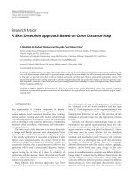
Monitoring peer
Monitoring peers corresponds to service or maintenance
units in real autonomic manufacturing systems. Such a tech-
nician (see right-hand side of Figure 8), for example, usu-
ally monitors the processing process, interferes if any prob-
lem occurs, or changes settings upon changes in the produc-
tion process (e.g., in case of a high-priority product which
must be manufactured as soon as possible). The table-top
systems prototypically implement a specialized type of such
a peer, the “monitoring peer”, which can be used by mainte-
nance and monitoring personal to observe all entities of the
FMS, to gather status information, and to interfere in case of
a problem. The monitoring peer can be used on an arbitrary
potentially small device and displays a monitoring and con-
trol interface for each entity of the FMS. A typical device for
the monitoring peer could be a usual tablet PC.
To summarize, within the peer-it system, mobile peers
adopt the roles of transport peers (able to move goods from
one space to another), processing peers (able to assemble or
manufacture goods), artifacts (representing the product or
good peers), and monitoring peers (able to inspect the con-
figuration and states of all other peers). All these peers inter-
act once they come into spatial proximity to each other, based
on the exchange of their role profiles related to their particu-
lar situation (see Figures 6 and 9). For example, the transport
peer is continuously aware of each processing peer within
the manufacturing cell (by periodically advertising each peer
and the process of profile matching), and each processing
peer is automatically aware of the transport peer; configuring
available processing and transport entities is not required.
10 EURASIP Journal on Embedded Systems
(a) (b)
Figure 7: Example profile of a product peer.
Based on the autonomy of processing peers and due to the
fact that they can communicate with other machines, a peer-
to-peer enabled machine can collect the main parts of the
required software and configuration from the environment.
The machine configures itself through the awareness of its
environment; moreover, each other entity of such an FMS
becomes aware of the new machine and can automatically
configure itself accordingly.
A. Ferscha et al. 11
(a)
(b)
(c)
Figure 8: Screenshot of monitoring peers: (i) general overview (a),
(ii) processing and artefact peers (b), and (iii) real-world control
center (c).
3.3. Capabilities of peer-it-based FMSs
In the sequel, we elaborate the autonomous computing ca-
pabilities explored in the table-top FMS system.
Checkpointing and self-routing
The concept of self-routing in FMS means that processing
plans stored on products determine their route plan for man-
ufacturing independently. The following steps are performed
within the table-top system.
(i) Each artifact carries a list of manufacturing steps (i.e.,
processing plan) to be performed for product comple-
tion. Artefact 1 (or product peer 1, shortened by “P1”
in what follows) finds, according to its plan, an appro-
priate manufacturing machine A (processing peer A,
or shortly “A”). The (single) autonomic transport sys-
tem (transport peer, “T”) is informed, picks up “P1”,
and carries it to “A”.
(ii) In the same way, product peer 2 (“P2”) finds adequate
processing machines B1 and B2 (“B1”, “B2”), and it is
transported, for instance, to “B1”. The additional dis-
crimination between B1 and B2 clarifies that all “Bs”
are machines of the same type (with the same process-
ing capabilities).
(a)
(b)
(c)
Figure 9: FMS demonstrator setting.
(a)
(b)
(c)
Figure 10: FMS concept of “self-routing.”
12 EURASIP Journal on Embedded Systems
(iii) The actual processing steps of products P1 and P2 are
performed on the corresponding machines A and B1.
After finishing, the subtask is checked off on the peers
processing checklist.
(iv) If “P1s” step has finished on machine “A”, the transport
peer being aware of that automatically moves to “A”
and picks up “P1”.
(v) As “P2” has finished on “B1” after the pickup of “P1”,
the transport peer collects it at “B1” (and handles now
both products “P1” and “P2”).
Each artifact on its own “knows” to which (kind of) ma-
chine (processing peer) it has to be transported with respect
to the manufacturing plan. Artifacts are embodied as ob-
ject peers; that is, they do not comprise any computational
or communication resources on their own, but they need to
consult a (nearby) proxy peer to use those services; in the
FMS demonstrator, the proxy is situated on the transport
peer (but it could also be an autonomous computer). The
artifact “tells” the transport peer via proxy about its destina-
tion, which in turn initiates transportation. If the execution
of one step is finished, the according subtask on peers pro-
cessing list is checked off; after that, the product looks for an
applicable processing peer for the succeeding step and no-
tifies the transport peer to perform carriage. At that time,
the product is also able to transfer a processing specification
to a processing peer (if there is no other machine capable of
performing the necessary processing step). Additionally, the
product itself can decide whether to perform subtask 3 prior
to subtask 2 in order to avoid standby times, for instance, if
manufacturing peer for subtask 2 is occupied and there is no
other machine capable of performing that step. All together,
processing of a product is fully flexible; the decision for the
processing machine which should be used, the execution of
the next step (if independent of other steps), and so forth are
on the respective product (even on each individual product,
meaning that this had not to be equal for the same class of
products).
As opposed to central control-based FMS, in the peer-
it-based FMS, the artefact itself decides which manufactur-
ing step is to be executed next and which processing machine
should be used for that.
Fault tolerance
The table-top FMS demonstration application implements
“fault tolerance” (the ability of a system to continue its tasks
in case of unexpected faults) as follows.
(i) The transport peer (“T”, in our case, a toy train) carries
artifacts like cars, diggers, and so forth (product peers)
from one processing machine to another, according to
the production plan stored on the product peer. Here it
is assumed that ¡?ehlt?¿ one artifact has to be processed
on machine “A” first and on machine “B” afterwards
(see Figure 11(a)).
(ii) If processing machine “A” fails during processing or
even during transportation to it (see Figure 11(b)), any
other machine (with adequate assembly capabilities,
and if not in use) can take over the production task
(a)
(b)
(c)
Figure 11: FMS concept of “fault tolerance”.
on the actual product peer. For that, the product peer
transfers a processing specification to an unassigned
processing peer, for example, machine “B”, and recon-
figures it (see Figure 11). It is also possible to choose a
nonrequired machine of type “A”. Transferring a pro-
cessing specification is accomplished by transferring
an OSGi processing bundle from one peer (in this case,
the product peer is implemented as object peer) to
another, utilizing the bundle repository and exchange
component depicted in Section 2.2.
(iii) At the same time or after reconfiguration, the product
is picked up at “A” (if it was already dropped there) and
transported to “B”, which becomes a new machine of
type “A” and is processed there.
As a consequence, “single points of failure” (SPOF) can be
prevented and the FMS can become more highly available
(until at least one processing peer for the required opera-
tions of an artefact peer is left, the manufacturing cell is fully
functional)—indeed overall performance of the cell is slower.
Enhanced fault tolerance is one key benefit of each peer-to-
peer system, evolving from the full autonomy of all involved
entities. In a standardized FMS (built up with a centralized
control unit), the “server” station is a typical “single point
of failure”, although there exist different approaches to avoid
this (replicated central stations, interconnected with the so-
called “heart beat” lines and fast takeover in case of break-
downs).
A. Ferscha et al. 13
(a)
(b)
(c)
Figure 12: FMS concept of “scalability”.
Scalability
Because of the ability to mix arbitrary peers (machines) in
one peer-it-based FMS application, P2P concepts can highly
improve scalability as well as flexibility (see next paragraph)
in such FMS. Assume a situation where two (maybe partly
finished) products P1 and P2 request the same manufac-
turing step at the same time, but there is only one suit-
able processing machine (“B”) available (see left-hand side
of Figure 12(a)).
(i) The FMS consists of several machines; some of them
are of type “B” and are maybe offline or occupied, and
the others are configured to work as “A” machines (for
performing corresponding processing steps of manu-
facturing goods). Products “P1” and “P2” therefore
had to be processed one after the other as shown in
Figure 12(b).
(ii) If during processing of the first item “P1” (in any case)
a failed machine comes online again or an “A” machine
is reconfigured to “B” (and therefore matches the nec-
essary processing criteria), transport peer “T” observes
this and automatically transports the second item “P2”
to this processing entity. Now, both products are pro-
cessed concurrently (see Figure 12(c)).
(iii) Another possibility for increasing the throughput of
the system is to endorse the flexible manufacturing sys-
tem during production with additional peer-to-peer
(a)
(b)
(c)
Figure 13: FMS concept of “flexibility”.
enabled processing machines (manufacturing peers)
of type “B” (or even transport peers if transporting is
the bottleneck in the running system).
If a faulty processing machine comes online or new machines
are added to the FMS, the provided operations of these man-
ufacturing peers are immediately available to the artefact
peers, leading to increased overall performance of the man-
ufacturing cell. Additional configuration (e.g., by a mainte-
nance worker) is not required when adding a new processing
peer to the FMS.
Flexibility
In an FMS, it should be easy to move a processing machine
from one FMS to another, to add a new processing machine,
or to reconfigure a processing machine. We illustrate the ca-
pabilities of the peer-it-based FMS along Figure 13.
(i) A problem for traditional flexible systems is the con-
figuration effort; whenever a machine is added to or
removed from the FMS, (a) the machine must be con-
figured before it can start working and (b) the control
station of the FMS must be (re-)configured to become
“aware” of the new situation.
(ii) Peer-to-peer concepts can heavily reduce this. Accord-
ing to the P2P paradigm, there is no (or only lit-
tle) need for reconfiguration; processing machines are
14 EURASIP Journal on Embedded Systems
automatically integrated in the manufacturing system,
and due to the fact that they can communicate with
other machines, a peer-to-peer enabled machine can
gather the main parts of the required software and
configuration from the environment (once they have a
connection to the communication infrastructure)and
configure itself.
(iii) Each other entity of a P2P-based FMS becomes aware
of a new machine and can automatically configure
itself accordingly. (Finally, peer-to-peer systems can
totally eliminate the need for basic configuration of
client/software or even network settings.)
A peer-it-based FMS can improve efficiency of traditional
FMS since the effort for configuration is minimal, hence
enabling the easy use of machines where they are cur-
rently needed. Besides, machine utilization can be improved
through the possibility of fast reconfiguration of processing
and transport peers.
4. CONCLUSIONS
The autonomous computing vision is based on the ability
of technology-rich, autonomous, self-induced, and context-
aware peers to operate as spontaneously interacting ensem-
bles. Key design principles for such systems are autonomic
behavior, context awareness, spontaneous interaction, se-
mantic interoperability, and self-contained implementation.
Aiming at a universal building block for autonomic comput-
ing systems and applications, we have developed an embed-
ded computing platform, together with a software architec-
ture and development framework, which adheres to all these
requirements, that is, peer-its. In this paper, we presented
the peer-it stick-on computer platform, integrating arbitrary
sensor and actuator technologies with wireless communica-
tion facilities, local storage, autonomic power supply, and
advanced processing abilities into a single device. Peer-its—
in their current and future appearance—are intended to be
attached to basically every real-world artifact like products,
machines, tools, furniture, clothing, or vehicles, much like
a 3M post-it note. A peer-to-peer-based coordination (soft-
ware) framework has been developed together with a small
memory footprint runtime environment, performing in ev-
ery node (peer) of a peer-it ensemble. The interaction prin-
ciple among peers in such an ensemble is strictly based on
the physical proximity among peers, their self-describing and
self-configuring interaction style, and their local sharing of
data, services, and resources.
Within a demonstrator setting in the domain of flexi-
ble manufacturing systems (FMSs), we have presented the
intuitive concept of peer-it stick-on computers, by attach-
ing them to machines typically involved in “autonomic” car
production. We have identified the peer roles involved in
FMS-based car production as (i) ar tifacts (or “product peers”,
i.e., cars), (ii) transport peers (carrying vehicles), (iii) process-
ing peers (production machinery), and (iv) monitoring peers
(quality control and maintenance facilities). Scenarios have
demonstrated (i) the ability of an artifact to occasionally find
transportation means according to its processing plan (“self
routing”), (ii) the ability of an autonomic product to spon-
taneously find supplementary production means in case of
faulty machinery (“fault tolerance”), (iii) the ability of an
autonomic product to get by any means the predefined pro-
cessing plan finished (“checkpointing”), and (iv) the ability
of a peer-it-based FMS ensemble to be flexibly extended by
adding additional “transport peers” and “processing peers”
on the fly, that is, without explicitly reconfiguring the whole
ensemble (“scalability”).
As a result, the demonstrator confirms our assumption,
that an FMS can be implemented as a fully distributed au-
tonomous system based on peer-its, avoiding any centralized
planning, management, control, or monitoring. Moreover,
essential key features of FMSs like self-management, fault tol-
erance, scalability, and flexibility are attained with the peer-it
systems in an almost effortless way. This is at the same time
empirical evidence for peer-its as a generic device for sensing,
computing, controlling, and communicating, representing a
universal enabling platform for autonomous computing.
REFERENCES
[1] J. O. Kephart and D. M. Chess, “The vision of autonomic com-
puting,” Computer, vol. 36, no. 1, pp. 41–50, 2003.
[2]C.Boutilier,R.Das,J.Kephart,G.Tesauro,andW.Walsh,
“Cooperative negotiation in autonomic systems using incre-
mental utility elicitation,” in Proceedings of the 19th Conference
on Uncertainty in Artificial Intelligence (UAI ’03), pp. 89–97,
Acapulco, Mexico, August 2003.
[3] M. M. Waldrop, “Autonomic computing—the technology of
self-management,” Tech. Rep., Woodrow Wilson International
Center for Scholars, Washington, DC, USA, 2003. http://wwics
.si.edu/foresight.
[4] J. Lifton, D. Seetharam, M. Broxton, and J. Paradiso, “Push-
pin computing system overview: a platform for distributed,
embedded, ubiquitous sensor networks,” in Proceedings of
the 1st International Conference on Pervasive Computing
(Pervasive ’02), F. Mattern and M. Naghshineh, Eds., vol. 2414,
pp. 139–151, Springer, Zurich, Switzerland, August 2002.
[5] K. van Laerhoven, A. Schmidt, and H W. Gellersen,
“Pin&play: networking objects through pins,” in Proceedings
of the 4th International Conference on Ubiquitous Computing
(UbiComp ’02), vol. 2498 of Lecture Notes in Computer Science,
pp. 219–228, Springer, Goteborg, Sweden, September-October
2002.
[6] K. van Laerhoven, N. Villar, M. Hakansson, and H W.
Gellersen, “Pin&play: bringing power and networking to wall-
mounted appliances,” Tech. Rep. LA1 4YR, United Kingdown
and Future Applications Lab, Viktoria Institute, Lancaster
University, Goteborg, Sweden, 2002.
[7] L. E. Holmquist, F. Mattern, B. Schiele, P. Alahuhta, M. Beigl,
and H W. Gellersen, “Smart-its friends: a technique for users
to easily establish connections between smart artefacts,” Tech.
Rep., PLAY Research Studio, Interactive Institute, Gothen-
burg, Sweden, 2001.
[8] L. E. Holmquist, F. Mattern, B. Schiele, P. Alahuhta, M. Beigl,
and H W. Gellersen, “Smart-its friends: a technique for users
to easily establish connections between smart artefacts,” in
Proceedings of the 3rd International Conference on Ubiquitous
Computing (Ubicomp ’01), vol. 2201, pp. 116–122, Springer,
Atlanta, Ga, USA, September-October 2001.
A. Ferscha et al. 15
[9] H W. Gellersen, “The smart-its project,” Department of
Computing, Internet resource, .
[10] M. Strohbach, G. Kortuem, H W. Gellersen, and C. Kray,
“Detection of safety hazards using cooperating chemical con-
tainers,” Tech. Rep. LA1 4YR, Computing Department, Lan-
caster University, Lancaster, UK, 2004.
[11] M. Strohbach, H W. Gellersen, G. Kortuem, and C. Kray,
“Cooperative artefacts: assessing real world situations with
embedded technology,” Tech. Rep. LA1 4YR, Computing De-
partment, Lancaster University, Lancaster, UK, 2004.
[12] H W. Gellersen, A. Schmidt, and M. Beigl, “Multi-sensor
context-awareness in mobile devices and smart artifacts,” Mo-
bile Networks and Applications, vol. 7, no. 5, pp. 341–351, 2002.
[13] H. Van Brussel, J. Wyns, P. Valckenaers, L. Bongaerts, and
P. Peeters, “Reference architecture for holonic manufacturing
systems: Prosa,” Computers in Industry, vol. 37, no. 3, pp. 255–
274, 1998.
[14] V. Ma
ˇ
r
´
ık and D. McFarlane, “Industrial adoption of agent-
based technologies,” IEEE Intelligent Systems, vol. 20, no. 1, pp.
27–35, 2005.
[15] V. Ma
ˇ
r
´
ık, R. W. Brennan, and M. Pechoucek, Eds., Holonic and
Multi-Agent Systems for Manufacturing, Second International
Conference on Industrial Applications, of Holonic and Multi-
Agent Systems (HoloMAS ’05), vol. 3593 of Lecture Notes in
Computer Science, Springer, Copenhagen, Denmark, August
2005.
[16] M. P
ˇ
echou
ˇ
cek, S. G. Thompson, J. W. Baxter, et al., “Agents
in industry: the best from the AAMAS 2005 industry track,”
Intelligent Systems, vol. 21, no. 2, pp. 86–87, 2006.
[17] F. Zambonelli and M. Mamei, “Spatial computing: an emerg-
ing paradigm for autonomic computing and communication,”
Tech. Rep., DISMI—Universita di Modena e Reggio Emilia,
Reggio Emilia, Italy, 2004.
[18] F. Zambonelli and M. Mamei, “Spatial computing: a recipe for
self-organization in distributed computing scenarios,” Tech.
Rep., DISMI—Universita di Modena e Reggio Emilia, Reggio
Emilia, Italy, 2005.
[19] M. Mamei and F. Zambonelli, “Spatial computing: the TOTA
approach,” in Self-star Properties in Complex Information Sys-
tems Conceptual and Practical Foundations, vol. 3460 of Lecture
Notes in Computer Science, pp. 307–324, Springer, Berlin, Ger-
many, 2005.
[20] A. W. Colombo, “Intelligent collaborative systems service-
oriented-architecture & agents (the sirena project),” in Am-
bient Intelligence on Industry Workshop, Armando Walter
Colombo Schneider Electric Product & Technology—H&O
HUB, Lisboa, Portugal, 2005.
[21] A. Ferscha, M. Hechinger, R. Mayrhofer, et al., “Bridging the
gap with P2P patterns,” in Proceedings of the Workshop on
Smart Object Systems in Conjunction with the 7th International
Conference on Ubiquitous Computing (UbiComp ’05),Tokyo,
Japan, September 2005.
[22] A. Ferscha, M. Hechinger, A. Riener, et al., “Context-aware
profiles,” in Proceedings of the Internat ional Conference on Au-
tonomic and Autonomous Systems (ICAS ’06),p.48,Silicon
Valley, Calif, USA, July 2006.
[23] A. G. Ganek and T. A. Corbi, “The dawning of the autonomic
computing era,” IBM Systems Journal, vol. 42, no. 1, pp. 5–18,
2003.
[24] Y. Wang, “On autonomous computing and cognitive pro-
cesses,” in Proceedings of the 3rd IEEE International Conference
on Cognitive Informatics (ICCI ’04), pp. 3–4, Victoria, Canada,
August 2004.
[25] P. Horn, “Autonomic computing: IBM’s perspective on the
state of information technology,” Tech. Rep., International
Business Machines Corporation (IBM), Armonk, NY, USA,
October 2001.
[26] L. E. Holmquist, H W. Gellersen, G. Kortuem, et al., “Build-
ing intelligent environments with smart-its,” IEEE Computer
Graphics and Applications, vol. 24, no. 1, pp. 56–64, 2004.
[27] The osgi-alliance, />[28] The oscar, />[29] The apache felix project, />.html.
[30] The equinox, />[31] The jxta, />[32] A. Ferscha, M. Hechinger, F. Ortner, and R. Mayrhofer, “Secur-
ing passive objects in mobile ad-hoc peer-to-peer networks,”
Electronic Notes in Theoretical Computer Science, vol. 85, no. 3,
pp. 105–121, 2003.
[33] A. Ferscha, M. Hechinger, R. Mayrhofer, and R. Oberhauser,
“A light-weight component model for peer-to-peer appli-
cations,” in Proceedings of the 24th Internat ional Conference
on Distributed Computing Systems Workshops (ICDCS ’04),
pp. 520–527, IEEE Computer Society Press, Hachioji, Japan,
March 2004.
[34] A. Ferscha and A. Riener, “Investigation report on sensor
technologies and communication standards, developed in the
scope of the strategic alliance siemens ag jku linz, pervasive
computing enabling architectures, autonomic peer systems,”
Tech. Rep., Institute for Pervasive Computing, Johannes Ke-
pler University Linz, Linz, Austria, 2005.
[35] A. Ferscha and A. Riener, “Pervasive computing technology
barometer-car to car communication, developed in the scope
of the strategic alliance siemens ag and jku linz, pervasive com-
puting enabling architectures, autonomic peer systems,” Tech.
Rep., Institute for Pervasive Computing, Johannes Kepler Uni-
versity Linz, Linz, Austria, 2005.
[36] The epcglobal, />[37] P. Spiess, H. Juetting, and H. Vogt, “Integrating sensor net-
works with business processes,” Tech. Rep., SAP Research,
Karlsruhe, Germany, 2004.
[38] D. V. Frunza, “Flexible manufacturing systems (fms),” 2006.
[39] A. Ferscha, M. Hechinger, and R. Mayrhofer, “The peer-to-
peer coordination framework architecture reference,” Tech.
Rep., Institute for Pervasive Computing, Johannes Kepler Uni-
versity Linz, Linz, Austria, 2004.