Báo cáo hóa học: " Research Article Optimal Design of Uniform Rectangular Antenna Arrays for Strong Line-of-Sight MIMO Channels" pdf
Bạn đang xem bản rút gọn của tài liệu. Xem và tải ngay bản đầy đủ của tài liệu tại đây (934.8 KB, 10 trang )
Hindawi Publishing Corporation
EURASIP Journal on Wireless Communications and Networking
Volume 2007, Article ID 45084, 10 pages
doi:10.1155/2007/45084
Research Article
Optimal Design of Uniform Rectangular Antenna Arrays
for Strong Line-of-Sight MIMO Channels
Frode Bøhagen,
1
P
˚
al Or ten,
2
and Geir Øien
3
1
Telenor Research and Innovation, Snarøyveien 30, 1331 Fornebu, Norway
2
Department of Informatics, UniK, University of Oslo (UiO) and Thrane & Thrane, 0316 Oslo, Norway
3
Department of Electronics and Telecommunications, Norwegian University of Science and Technology (NTNU),
7491 Trandheim, Norway
Received 26 October 2006; Accepted 1 August 2007
Recommended by Robert W. Heath
We investigate the optimal design of uniform rectangular arrays (URAs) employed in multiple-input multiple-output communi-
cations, where a st rong line-of-sig ht (LOS) component is present. A general geometrical model is introduced to model the LOS
component, which allows for any orientation of the transmit and receive arrays, and incorporates the uniform linear array as a
special case of the URA. A spherical wave propagation model is used. Based on this model, we derive the optimal array design
equations with respect to mutual information, resulting in orthogonal LOS subchannels. The equations reveal that it is the dis-
tance between the antennas projected onto the plane perpendicular to the transmission direction that is of importance with respect
to design. Further, we investigate the influence of nonoptimal design, and derive analytical expressions for the singular values of
the LOS matrix as a function of the quality of the array design. To evaluate a more realistic channel, the LOS channel matrix is
employed in a Ricean channel model. Performance results show that even with some deviation from the optimal design, we get
better performance than in the case of uncorrelated Rayleigh subchannels.
Copyright © 2007 Frode Bøhagen et al. This is an open access article distributed under the Creative Commons Attribution License,
which permits unrestricted use, distribution, and reproduction in any medium, provided the original work is properly cited.
1. INTRODUCTION
Multiple-input multiple-output (MIMO) technology is a
promising tool for enabling spectrally efficient future wire-
less applications. A lot of research effort has been put into the
MIMO field since the pioneering work of Foschini and Gans
[1] and Telatar [2], and the technology is already hitting the
market [3, 4]. Most of the work on wireless MIMO systems
seek to utilize the decorrelation between the subchannels in-
troduced by the multipath propagation in the wireless envi-
ronment [5]. Introducing a strong line-of-sight (LOS) com-
ponent for such systems is positive in the sense that it boosts
the signal-to-noise ratio (SNR). However, it will also have a
negative impact on MIMO performance as it increases the
correlation between the subchannels [6].
In [7], the possibility of enhancing performance by
proper antenna array design for MIMO channels with a
strong LOS component was investigated, and it was shown
that the performance can actual ly be made superior for pure
LOS subchannels compared to fully decorrelated R ayleigh
subchannels with equal SNR. The authors of the present
paper have previously studied the optimal design of uni-
form linear arrays (ULAs) with respect to mutual informa-
tion (MI) [8, 9], and have given a simple equation for the
optimal design. Furthermore, some work on the design of
uniform rectangular arrays (URAs) for MIMO systems is pre-
sented in [10], where the optimal design for the special case
of two broadside URAs is found, and the optimal through-
put performance was identified to be identical to the optimal
Hadamard bound. The design is based on taking the spheri-
cal nature of the electromagnetic wave propagation into ac-
count, which makes it possible to achieve a high rank LOS
channel matrix [11]. Examples of real world measurements
that support this theoretical work can be found in [12, 13].
Inthispaper,weextendourworkfrom[8], and use the
same general procedure to investigate URA design. We intro-
duce a new general geometrical model that can describe any
orientation of the transmit (Tx), receive (Rx) URAs, and also
incorporate ULAs as a special case. Again, it should be noted
that a spherical wave propagation model is employed, in con-
trast to the more commonly applied approximate plane-wave
model. This model is used to derive new equations for the
2 EURASIP Journal on Wireless Communications and Networking
optimal design of the URAs with respect to MI. The results
are more general than those presented in an earlier work, and
the cases of two ULAs [8] and two broadside URAs [10]can
be identified as two special cases. The proposed principle is
best suited for fixed systems, for example, fixed wireless ac-
cess and radio relay systems, because the optimal design is
dependent on the Tx-Rx distance and on the orientation of
the two URAs. Furthermore, we include an analysis of the in-
fluence of nonoptimal design, and analytical expressions for
the singular values of the LOS matrix are derived as a func-
tion of the quality of the array design. The results are useful
for system designers both when designing new systems, as
well as when evaluating the performance of existing systems.
The rest of the paper is organized as follows. Section 2
describes the system model used. In Section 3,wepresent
the geometrical model from which the general results are de-
rived. The derivation of the optimal design equations is given
in Section 4, while the eigenvalues of the LOS channel matrix
are discussed in Section 5 . Performance results are shown in
Section 6, while conclusions are drawn in Section 7.
2. SYSTEM MODEL
The wireless MIMO transmission system employs N Tx an-
tennas and M Rx antennas when transmitting information
over the channel. Assuming slowly varying and frequency-flat
fading channels, we model the MIMO transmission in com-
plex baseband as [5]
r
=
η · Hs + n,(1)
where r
∈ C
M×1
is the received signal vector, s ∈ C
N×1
is the transmitted signal vector, H ∈ C
M×N
is the normal-
ized channel mat rix linking the Tx antennas with the Rx an-
tennas, η is the common power attenuation over the chan-
nel, and n
∈ C
M×1
is the additive white Gaussian noise
(AWGN) vector. n contains i.i.d. circularly symmetric com-
plex Gaussian elements with zero mean and variance σ
2
n
, that
is, n ∼ CN (0
M×1
, σ
2
n
· I
M
),
1
where I
M
is the M × M identity
matrix.
As mentioned above, H is the normalized channel ma-
trix, which implies that each element in H has unit average
power; consequently, the average SNR is independent of H.
Furthermore, it is assumed that the total transmit power is
P, and all the subchannels experience the same path loss as
accounted for in η, resulting in the total average received
SNR at one Rx antenna being
γ = ηP/σ
2
n
.Weapplys ∼
CN (0
N×1
,(P/N) ·I
N
), which means that the MI of a MIMO
transmission described by (1)becomes[2]
2
I =
U
p=1
log
2
1+
γ
N
μ
p
bps/Hz, (2)
1
CN (x, Y) denotes a complex symmetric Gaussian distributed random
vector,withmeanvectorx and covariance matrix Y.
2
Applying equal power Gaussian distributed inputs in the MIMO system is
capacity achieving in the case of a Rayleigh channel, but not necessarily in
the Ricean channel case studied here [14]; consequently, we use the term
MI instead of capacity.
where U = min(M, N)andμ
p
is the pth eigenvalue of W
defined as
W
=
⎧
⎨
⎩
HH
H
, M ≤ N,
H
H
H, M>N,
(3)
where (
·)
H
is the Hermitian transpose operator.
3
One way to model the channel matrix is as a sum of two
components: a LOS component: and an non-LOS (NLOS)
component. The ratio between the power of the two com-
ponents gives the Ricean K-factor [15, page 52]. We express
the normalized channel matrix in terms of K as
H
=
K
1+K
· H
LOS
+
1
1+K
· H
NLOS
,(4)
where H
LOS
and H
NLOS
are the channel matrices containing
the LOS and NLOS channel responses, respectively. In this
paper, H
NLOS
is modeled as an uncorrelated Rayleigh matrix,
that is, vec(H
NLOS
) ∼ CN (0
MN×1
, I
MN
), where vec(·) is the
matrix vectorization (stacking the columns on top of each
other). In the next section, the entries of H
LOS
will be de-
scribed in detail, while in the consecutive sections, the con-
nection between the URA design and the properties of H
LOS
will be addressed. The influence of the stochastic channel
component H
NLOS
on performance is investigated in the re-
sults section.
3. THE LOS CHANNEL: GEOMETRICAL MODEL
When investigating H
LOS
in this section, we only consider the
direct components between the Tx and Rx. The optimal de-
sign, to be presented in Section 4, is based on the fact that
the LOS components from each of the Tx antennas arrive at
the Rx array with a spherical wavefront. Consequently, the
common approximate plane wave model, where the Tx and
Rx arrays are assumed to be points in space, is not applicable
[11]; thus an important part of the contribution of this paper
is to characterize the received LOS components.
The principle used to model H
LOS
is ray-tracing [7]. Ray-
tracing is based on finding the path lengths from each of the
Tx antennas to each of the Rx antennas, and employing these
path lengths to find the corresponding received phases. We
will see later how these path lengths characterize H
LOS
,and
thus its rank and the MI.
To make the derivation in Section 4 more general, we do
not distinguish between the Tx and the Rx, but rather the
side with the most antennas and the side with the fewest an-
tennas (the detailed motivation behind this decision is given
in the first paragr aph of Section 4). We introduce the nota-
tion V
= max(M, N), consequently we refer to the side with
V antennas as the Vx, and the side with U antennas as the
Ux.
We restrict the antenna elements, both at the Ux and at
the Vx, to be placed in plane URAs. Thus the antennas are
3
μ
p
also corresponds to the pth singular value of H squared.
Frode Bøhagen et al. 3
n
1
d
(1)
U
(1, 0) (1, 1) (1, 2)
(0, 0) (0, 1) (0, 2)
d
(2)
U
n
2
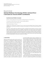
Figure 1: An example of a Ux URA with U = 6 antennas (U
1
= 2
and U
2
= 3).
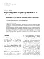
θ
φ
n
1
x
y
z
Figure 2: Geometrical illustration of the first principal direction of
the URA.
placed on lines going in two orthogonal principal directions,
forming a lattice structure. The two principal directions are
characterized with the vectors n
1
and n
2
, w hile the uniform
separation in each direction is denoted by d
(1)
and d
(2)
.The
numbers of antennas at the Ux in the first and second princi-
pal directions are denoted by U
1
and U
2
,respectively,andwe
have U
= U
1
· U
2
. The position of an antenna in the lattice
is characterized by its index in the first and second principal
direction, that is, (u
1
, u
2
), where u
1
∈{0, , U
1
− 1} and
u
2
∈{0, , U
2
−1}. As an example, we have illustrated a Ux
array with U
1
= 2andU
2
= 3inFigure 1. The same defini-
tions are used at the Vx side for V
1
, V
2
, v
1
,andv
2
.
ThepathlengthbetweenUxantenna(u
1
, u
2
) and Vx
antenna (v
1
, v
2
)isdenotedbyl
(v
1
,v
2
)(u
1
,u
2
)
(see Figure 4).
Since the elements of H
LOS
are assumed normalized as men-
tioned earlier, the only parameters of interest are the received
phases. The elements of H
LOS
then become
(H
LOS
)
m,n
= e
( j2π/λ)l
(v
1
,v
2
)(u
1
,u
2
)
,(5)
where (
·)
m,n
denotes the element in row m and column n,
and λ is the wavelength. The mapping between m, n,and
(v
1
, v
2
), (u
1
, u
2
) depends on the dimension of the MIMO sys-
tem, for example, in the case M>N,wegetm
= v
1
· V
2
+
v
2
+1andn = u
1
· U
2
+ u
2
+ 1. The rest of this section
is dedicated to finding an expression for the different path
lengths. The procedure employed is based on pure geometri-
cal considerations.
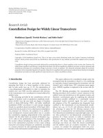
α
n
2
n
1
x
y
Figure 3: Geometrical illustration of the second principal direction
of the URA.
We start by describing the geometry of a single URA; af-
terwards, two such URAs are utilized to describe the com-
munication link. We define the local origo to be at the lower
corner of the URA, and the first principal direction as shown
in Figure 2, where we have employed spherical coordinates
to describe the direction with the angles θ
∈ [0, π/2] and
φ
∈ [0, 2π]. The unit vector for the first principal direc-
tion n
1
, with respect to the Cartesian coordinate system in
Figure 2,isgivenby[16, page 252]
n
1
= sin θ cos φ n
x
+sinθ sin φ n
y
+cosθ n
z
,(6)
where n
x
, n
y
,andn
z
denote the unit vectors in their respec-
tive directions.
The second principal direction has to be orthogonal to
the first; thus we know that n
2
is in the plane, which is or-
thogonal to n
1
. The two axes in this orthogonal plane are re-
ferred to as x
and y
.TheplaneisillustratedinFigure 3,
where n
1
is coming perpendicularly out of the plane, and we
have introduced the third angle α to describe the angle be-
tween the x
-axis and the second principal direction. To fix
this plane described by the x
-andy
-axis to the Cartesian
coordinate system in Figure 2, we choose the x
-axis to be
orthogonal to the z-axis, that is, placing the x
-axis in the
xy-plane. The x
unit vector then becomes
n
x
=
1
n
1
× n
z
n
1
× n
z
= sin φn
x
− cos φn
y
. (7)
Since origo is defined to be at the lower corner of the URA,
we require α
∈ [π,2π]. Further, we get the y
unit vector
n
y
=
1
n
1
× n
x
n
1
× n
x
= cos θ cos φn
x
+cosθ sin φn
y
− sin θn
z
.
(8)
Note that when θ
= 0andφ = π/2, then n
x
= n
x
and n
y
=
n
y
. Based on this description, we observe from Figure 3 that
the second principal direction has the unit vector
n
2
= cos αn
x
+sinαn
y
. (9)
These unit vectors, n
1
and n
2
,cannowbeemployedto
describe the position of any antenna in the URA. The posi-
tion difference, relative to the local origo in Figure 2,between
4 EURASIP Journal on Wireless Communications and Networking
Vx
Ux
x
z
y
l
(v
1
,v
2
)(u
1
,u
2
)
R
(u
1
, u
2
)
(v
1
, v
2
)
Figure 4: The transmission system investigated.
two neighboring antennas placed in the first principal direc-
tion is
k
(1)
= d
(1)
n
1
= d
(1)
sin θ cos φn
x
+sinθ sin φn
y
+cosθn
z
,
(10)
where d
(1)
is the distance between two neighboring antennas
in the first principal direction. The corresponding position
difference in the second pr incipal direction is
k
(2)
= d
(2)
n
2
= d
(2)
(cos α sin φ +sinα cos θ cos φ)n
x
+ (sin α cos θ sin φ − cos α cos φ)n
y
− sin α sin θn
z
,
(11)
where d
(2)
is the distance between the antennas in the second
principal direction. d
(1)
and d
(2)
can of course take different
values, both at the Ux and at the Vx; thus we get two pairs of
such distances.
We now employ two URAs as just described to model the
communication link. When defining the reference coordi-
nate system for the communication link, we choose the lower
corner of the Ux URA to be the global origo, and the y-axis is
taken to be in the direction from the lower corner of the Ux
URA to the lower corner of the Vx URA. To determine the
z-andx-axes, we choose the first principal direction of the
Ux URA to be in the yz-plane, that is, φ
U
= π/2. The system
is illustrated in Figure 4,whereR is the distance between the
lower corner of the two URAs. To find the path lengths that
we are searching for, we define a vector from the global origo
to Ux antenna (u
1
, u
2
)as
a
(u
1
,u
2
)
U
= u
1
· k
(1)
U
+ u
2
· k
(2)
U
, (12)
and a vector from the global origo to Vx antenna (v
1
, v
2
)as
a
(v
1
,v
2
)
V
= R ·n
y
+ v
1
· k
(1)
V
+ v
2
· k
(2)
V
. (13)
All geometrical parameters in k
(1)
and k
(2)
(θ, φ, α, d
(1)
, d
(2)
)
in these two expressions have a subscript U or V to distin-
guish between the two sides in the communication link. We
can now find the distance between Ux antenna (u
1
, u
2
)and
Vx antenna (v
1
, v
2
) by taking the Euclidean norm of the vec-
tor difference:
l
(v
1
,v
2
)(u
1
,u
2
)
=
a
(v
1
,v
2
)
V
− a
(u
1
,u
2
)
U
(14)
=
l
2
x
+
R + l
y
2
+ l
2
z
1/2
(15)
≈ R + l
y
+
l
2
x
+ l
2
z
2R
. (16)
Here, l
x
, l
y
,andl
z
represent the distances between the two
antennas in these directions when disregarding the distance
between the URAs R. In the transition from (15)to(16), we
perform a Maclaurin series expansion to the first order of the
square root expression, that is,
√
1+a ≈ 1+a/2, which is
accurate when a
1. We also removed the 2 · l
y
term in the
denominator. Both these approximations are good as long as
R
l
x
, l
y
, l
z
.
It is important to note that the geometrical model just
described is general, and allows any orientation of the two
URAs used in the communication link. Another interesting
observation is that the geometrical model incorporates the
case of ULAs, for example, by employing U
2
= 1, the Ux ar-
ray becomes a ULA. This will be exploited in the analysis in
the next section. A last but very important observation is that
we have taken the spherical nature of the electromagnetic
wave propagation into account, by applying the actual dis-
tance between the Tx and Rx antennas when considering the
received phase. Consequently, we have not put any restric-
tions on the rank of H
LOS
, that is, rank(H
LOS
) ∈{1, 2, , U}
[11].
4. OPTIMAL URA/ULA DESIGN
In this section, we derive equations for the optimal
URA/ULA design with respect to MI when transmitting over
a pure LOS MIMO channel. From (2), we know that the im-
portant channel parameter with respect to MI is the
{μ
p
}.
Further, in [17, page 295], it is shown that the maximal MI
is achieved when the
{μ
p
} are all equal. This situation oc-
curs when all the vectors h
(u
1
,u
2
)
(i.e., columns (rows) of H
LOS
when M>N(M ≤ N)), containing the channel response be-
tween one Ux antenna (u
1
, u
2
) and all the Vx antennas, that
is,
h
(u
1
,u
2
)
=
e
( j2π/λ)l
(0,0)(u
1
,u
2
)
, e
( j2π/λ)l
(0,1)(u
1
,u
2
)
, , e
( j2π/λ)l
((V
1
−1),(V
2
−1))(u
1
,u
2
)
T
,
(17)
are orthogonal to each other, resulting in μ
p
= V,forp ∈
{
1, , U}.Here,(·)
T
is the vector transpose operator. This
requirement is actually the motivation behind the choice to
distinguish between Ux and Vx instead of Tx and Rx. By bas-
ing the analysis on Ux and Vx, we get one general solution,
instead of getting one solution valid for M>Nand another
for M
≤ N.
When the orthogonality requirement is fulfilled, all the U
subchannels are or thogonal to each other. When doing spa-
tial multiplexing on these U orthogonal subchannels, the op-
timal detection scheme actually becomes the matched filter,
Frode Bøhagen et al. 5
that is, H
H
LOS
. The matched filter results in no interference
between the subchannels due to the orthogonality, and at the
same time maximizes the SNR on each of the subchannels
(maximum ratio combining).
A consequence of the orthogonality requirement is that
the inner product between any combination of two different
such vectors should be equal to zero. This can be expressed
as h
H
(u
1
b
,u
2
b
)
h
(u
1
a
,u
2
a
)
= 0, where the subscripts a and b are em-
ployed to distinguish between the two different Ux antennas.
The orthogonality requirement can then be written as
V
1
−1
v
1
=0
V
2
−1
v
2
=0
e
j2π/λ(l
(v
1
,v
2
)(u
1
a
,u
2
a
)
−l
(v
1
,v
2
)(u
1
b
,u
2
b
)
)
= 0. (18)
By factorizing the path length difference in the parentheses
in this expression with respect to v
1
and v
2
,itcanbewritten
in the equivalent form
V
1
−1
v
1
=0
e
j2π(
β
11
+
β
12
)v
1
·
V
2
−1
v
2
=0
e
j2π(
β
21
+
β
22
)v
2
= 0, (19)
where
β
ij
= β
ij
(u
j
b
− u
j
a
), and the different β
ij
saredefined
as follows:
4
β
11
=
d
(1)
V
d
(1)
U
V
1
λR
cos θ
V
cos θ
U
, (20)
β
12
=
d
(1)
V
d
(2)
U
V
1
λR
sin θ
V
cos φ
V
cos α
U
− cos θ
V
sin α
U
sin θ
U
,
(21)
β
21
=−
d
(2)
V
d
(1)
U
V
2
λR
sin α
V
sin θ
V
cos θ
U
, (22)
β
22
=
d
(2)
V
d
(2)
U
V
2
λR
cos α
U
cos α
V
sin φ
V
+cosα
U
sin α
V
cos θ
V
cos φ
V
+sinα
V
sin α
U
sin θ
V
sin θ
U
.
(23)
The orthogonality requirement in (19) can be simplified by
employing the expression for a geometric sum [16, page 192]
and the relation sin x
= (e
jx
− e
−jx
)/2j [16, page 128] to
sin
π
β
11
+
β
12
sin
(π/V
1
)
β
11
+
β
12
=ζ
1
·
sin
π
β
21
+
β
22
sin
(π/V
2
)
β
21
+
β
22
=ζ
2
= 0.
(24)
Orthogonal subchannels, and thus maximum MI, are
achieved if (24) is fulfilled for all combinations of (u
1
a
, u
2
a
)
and (u
1
b
, u
2
b
), except when (u
1
a
, u
2
a
) = (u
1
b
, u
2
b
).
4
This can be verified by employing the approximate path length from (16)
in (18).
The results above clearly show how achieving orthogo-
nal subchannels is dependent on the geometrical parame-
ters, that is, the design of the antenna arrays. By investigat-
ing (20)–(23) closer, we observe the following inner product
relation:
β
ij
=
V
i
λR
k
( j)T
U
k
(i)
V
∀i, j ∈{1, 2}, (25)
where
k
(i)
= k
(i)
x
n
x
+k
(i)
z
n
z
, that is, the vectors defined in (10)
and (11) where the y-term is set equal to zero. Since solving
(24) is dependent on applying correct values of β
ij
,wesee
from (25) that it is the extension of the arrays in the x-and
z-direction that are crucial with respect to the design of or-
thogonal subchannels. Moreover, the optimal design is inde-
pendent of the array extension in the y-direction (direction
of transmission). The relation in (25) will be exploited in the
analysis to follow to give an alternative projection view on
the results.
Both ζ
1
and ζ
2
,whicharedefinedin(24), are
sin(x)/ sin(x/V
i
) expressions. For these to be zero, the sin(x)
in the nominator must be zero, while the sin(x/V
i
) in the de-
nominator is non-zero, which among other things leads to
requirements on the dimensions of the URAs/ULAs, as will
be seen in the next subsections. Furthermore, ζ
1
and ζ
2
are
periodic functions, thus (24) has more than one solution. We
will focus on the solution corresponding to the smallest ar-
rays, both because we see this as the most interesting case
from an implementation point of view, and because it would
not be feasible to investigate all possible solutions of (24).
From (20)–(23), we see that the array size increases with in-
creasing β
ij
, therefore, in this paper, we will restrict the anal-
ysis to the case where the relevant
|β
ij
|≤1, which are found,
by investigating (24), to be the smallest values that produce
solutions. In the next four subsections, we will systematically
go through the possible different combinations of URAs and
ULAs in the communications link, and give solutions of (24)
if possible.
4.1. ULA at Ux and ULA at Vx
We start with the simplest case, that is, both Ux and Vx em-
ploying ULAs. This is equivalent to the scenario we studied
in [8]. In this case, we have U
2
= 1 giving
β
12
=
β
22
= 0, and
V
2
= 1 giving ζ
2
= 1, therefore, we only need to consider
β
11
.
Studying (24), we find that the only solution with our array
size restriction is
|β
11
|=1, that is,
d
(1)
V
d
(1)
U
=
λR
V
1
cos θ
V
cos θ
U
, (26)
which is identical to the result derived in [8]. The solution is
given as a product d
U
d
V
, and in accordance with [8], we re-
fer to this product as the antenna separation product (ASP).
When the relation in (26) is achieved, we have the optimal
design in terms of MI, corresponding to orthogonal LOS sub-
channels.
6 EURASIP Journal on Wireless Communications and Networking
Projection view
Motivated by the observation in (25), we reformulate (26)as
(d
(1)
V
cos θ
V
) · (d
(1)
U
cos θ
U
) = λR/V
1
. Consequently, we ob-
serve that the the product of the antenna separations pro-
jected along the local z-axis at both sides of the link should
be equal to λR/V
1
.Thez-direction is the only direction of
relevance due to the fact that it is only the array extension
in the xz-plane that is of interest (cf. (25)), and the fact that
the first (and only) principal direction at the Ux is in the yz-
plane (i.e., φ
U
= π/2).
4.2. URAatUxandULAatVx
Since Vx is a ULA, we have V
2
= 1 giving ζ
2
= 1, thus to
get the optimal design, we need ζ
1
= 0. It turns out that with
the aforementioned array size restriction (
|β
ij
|≤1), it is not
possible to find a solution to this problem, for example, by
employing
|β
11
|=|β
12
|=1, we observe that ζ
1
= 0for
most combinations of Ux antennas, except when u
1
a
+ u
2
a
=
u
1
b
+ u
2
b
, which gives ζ
1
= V
1
. By examining this case a bit
closer, we find that the antenna elements in the URA that are
correlated, that is, g iving ζ
1
= V
1
, are the diagonal elements
of the URA. Consequently, the optimal design is not possible
in this case.
Projection view
By employing the projection view, we can reveal the rea-
son why the diagonal elements become correlated, and thus
why a solution is not possible. Actually, it turns out that the
diagonal of the URA projected on to the xz-plane is per-
pendicular to the ULA projected on to the xz-plane when
|β
11
|=|β
12
|=1. This can be verified by applying (25)to
show the following relation:
k
(1)
U
−
k
(2)
U
T
diagonal of URA
·
k
(1)
V
= 0. (27)
Moreover, the diagonal of the URA can be viewed as a ULA,
and when two ULAs are perpendicular aligned in space, the
ASP goes towards infinity (this c an be verified by employing
θ
V
→ π/2in(26)). This indicates that it is not possible to do
the optimal design when this perpendicularity is present.
4.3. ULA at Ux and URA at Vx
As mentioned earlier, a ULA at Ux gives U
2
= 1, resulting in
(u
2
b
− u
2
a
) = 0, and thus
β
12
=
β
22
= 0. Investigating the
remaining expression in (24), we see that the optimal design
is achieved when
|β
11
|=1ifV
1
≥ U, giving ζ
1
= 0, or
|β
21
|=1ifV
2
≥ U, giving ζ
2
= 0, that is,
d
(1)
V
d
(1)
U
=
λR
V
1
cos θ
V
cos θ
U
if V
1
≥ U, or (28)
d
(2)
V
d
(1)
U
=
λR
V
2
sin θ
V
sin α
V
cos θ
U
if V
2
≥ U. (29)
Furthermore, the optimal design is also achieved if both the
above ASP equations are fulfilled simultaneously, and either
q/V
1
/∈ Z or q/V
2
/∈ Z,forallq<U. This guarantees either
ζ
1
= 0orζ
2
= 0 for all combinations of u
1
a
and u
1
b
.
Projection view
A similar reformulation as performed in Section 4.1 can be
done for this scenario. We see that both ASP equations, (28)
and (29), contain the term cos θ
U
, which projects the antenna
distance at the Ux side on the z-axis. The other trigonometric
functions project the Vx antenna separation on to the z-axis,
either based on the first principal direction (28)orbasedon
the second principal direction (29).
4.4. URA at Ux and URA at Vx
In this last case, when both Ux and Vx are URAs, we have
U
1
, U
2
, V
1
, V
2
> 1. By investigating (20)–(24), we observe
that in order to be able to solve (24), at least one β
ij
must
be zero. This indicates that the optimal design in this case
is only possible for some array orientations, that is, values
of θ, φ,andα, giving one β
ij
= 0. To solve (24)whenone
β
ij
= 0, we observe the following requirement on the β
ij
s:
|β
11
|=|β
22
|=1andV
1
≥ U
1
, V
2
≥ U
2
or |β
12
|=|β
21
|=1
and V
1
≥ U
2
, V
2
≥ U
1
.
This is best illustrated through an example. For instance,
we can look at the case where α
V
= 0, which results in β
21
=
0. From (24), we observe that when β
21
= 0and|β
22
|=
1, we always have ζ
2
= 0ifV
2
≥ U
2
,exceptwhen(u
2
b
−
u
2
a
) = 0. Thus to get orthogonality in this case as well, we
need
|β
11
|=1andV
1
≥ U
1
. Therefore, the optimal design
for this example becomes
d
(1)
V
d
(1)
U
=
λR
V
1
cos θ
V
cos θ
U
, V
1
≥ U
1
, (30)
d
(2)
V
d
(2)
U
=
λR
V
2
cos α
U
sin φ
V
, V
2
≥ U
2
. (31)
The special case of two broadside URAs is revealed by fur-
ther setting α
U
= 0, θ
U
= 0, θ
V
= 0, and φ
V
= π/2in(30)
and (31). The optimal ASPs are then given by
d
(1)
V
d
(1)
U
=
λR
V
1
, V
1
≥ U
1
; d
(2)
V
d
(2)
U
=
λR
V
2
, V
2
≥ U
2
.
(32)
This corresponds exactly to the result given in [10], which
shows the generality of the equations derived in this work
and how they contain previous work as special cases.
Projection view
We now look at the example where α
V
= 0withaprojec-
tion view. We observe that in (30), both antenna separations
in the first principal directions are projected along the z-axis
at Ux and Vx, and the product of these two distances should
be equal to λR/V
1
.In(31), the antenna separ a tions along the
second principal direction are projected on the x-axis at Ux
Frode Bøhagen et al. 7
and Vx, and the product should be equal to λR/V
2
. These
results clearly show that it is the extension of the arr ays in
the plane perpendicular to the transmission direction that
is crucial. Moreover, the correct extension in the xz-plane is
dependent on the wavelength, tr ansmission distance, and di-
mension of the Vx.
4.5. Practical considerations
We observe that the optimal design equations from previ-
ous subsections are all on the same form, that is, d
V
d
U
=
λR/V
i
X,whereX is given by the orientation of the arrays. A
first comment is that utilizing the design equations to achieve
high performance MIMO links is best suited for fi xed sys-
tems (such as wireless LANs with LOS conditions,
5
broad-
band wireless access, radio relay systems, etc.) since the op-
timal design is dependent on both the orientation and the
Tx-Rx distance. Another important aspect is the size of the
arrays. To keep the array size reasonable,
6
the product λR
should not be too large, that is, the scheme is best suited for
high frequency and/or short range communications. Note
that these properties agree well with systems that have a fairly
high probability of having a strong LOS channel component
present. The orientation also affects the array size, for exam-
ple, if X
→ 0, the optimal antenna separation goes towards
infinity. As discussed in the previous sections, it is the array
extension in the xz-plane that is important with respect to
performance, consequently, placing the arrays in this plane
minimizes the size required.
Furthermore, we observe that in most cases, even if one
array is fully specified, the optimal design is still possible. For
instance, from (30)and(31), we see that if d
(1)
and d
(2)
are
givenforoneURA,wecanstilldotheoptimaldesignby
choosing appropriate values for d
(1)
and d
(2)
for the other
URA. This is an important property for centralized systems
utilizing base stations (BSs), which allows for the optimal de-
sign for the different communication links by adapting the
subscriber units’ arr ays to the BS array.
5. EIGENVALUES OF W
As in the previous two sec tions, we focus on the pure LOS
channel matrix in this a nalysis. From Section 4, we know that
in the case of optimal array design, we get μ
p
= V for all p,
that is, all the eigenvalues of W are equal to V. An interest-
ing question now is: What happens to the μ
p
s if the design
deviates from the optimal as given in Section 4? In our analy-
sis of nonoptimal design, we make use of
{β
ij
}.Fromabove,
we know that the optimal design, requiring the smallest an-
tenna arrays, was found by setting the relevant
|β
ij
| equal to
zero or unity, depending on the transmission scenario. Since
{β
ij
} are functions of the geometrical parameters, studying
5
This is of course not the case for all wireless LANs.
6
What is considered as reasonable, of course, depends on the application,
and may, for example, vary for WLAN, broadband wireless access, and
radio relay systems.
the deviation from the optimal design is equivalent to study-
ing the behavior of
{μ
p
}
U
p
=1
, when the relevant β
ij
sdeviate
from the optimal ones. First, we give a simplified expression
for the eigenvalues of W as functions of β
ij
. Then, we look
at an interesting special case where we give explicit analytical
expressions for
{μ
p
}
U
p
=1
and describe a method for character-
izing nonoptimal designs.
We employ the path length found in (16) in the H
LOS
model. As in [8], we utilize the fact that the eigenvalues of the
previously defined Hermitian matrix W are the same as for a
real symmetric matrix
W defined by W = B
H
WB,whereB
is a unitary matrix.
7
For the URA case studied in this paper,
it is straightforward to show that the elements of
W are (cf.
(24))
(
W)
k,l
=
sin
π
β
11
+
β
12
sin
(π/V
1
)
β
11
+
β
12
·
sin
π
β
21
+
β
22
sin
(π/V
2
)
β
21
+
β
22
,
(33)
where k
= u
1
a
U
2
+u
2
a
+1and l = u
1
b
U
2
+u
2
b
+1.We can now
find the eigenvalues
{μ
p
}
U
p
=1
of W by solving det(
W −I
U
μ) =
0, where det(·) is the matrix determinant operator. Analyt-
ical expressions for the eigenvalues can be calculated for all
combinations of ULA and URA communication links by us-
ing a similar procedure to that in Section 4.Theeigenvalue
expressions become, however, more and more involved for
increasing values of U.
5.1. Example: β
11
= β
22
= 0 or β
12
= β
21
= 0
As an example, we look at the special case that occurs when
β
11
= β
22
= 0orβ
12
= β
21
= 0. This is true for some ge-
ometrical parameter combinations, when employing URAs
both at Ux and Vx, for example, the case of two broadside
URAs. In this situation, we see that the matrix
W from (33)
can be written as a Kronecker product of two square matrices
[10], that is,
W =
W
1
⊗
W
2
, (34)
where
W
i
k,l
=
sin
πβ
ij
(k − l)
sin
π(β
ij
/V
i
)(k − l)
. (35)
Here, k, l
∈{1, 2, , U
j
} and the subscript j ∈{1, 2} is de-
pendent on β
ij
.If
W
1
has the eigenvalues {μ
(1)
p
1
}
U
j
p
1
=1
,and
W
2
has the eigenvalues {μ
(2)
p
2
}
U
j
p
2
=1
, we know from matrix theory
that the matrix
W has the eigenvalues
μ
p
= μ
(1)
p
1
· μ
(2)
p
2
, ∀p
1
, p
2
. (36)
7
This implies that det(W−λI) = 0 ⇒ det(B
H
WB−λB
H
IB) = 0 ⇒ det(
W−
λI) = 0.
8 EURASIP Journal on Wireless Communications and Networking
Expressions for μ
(i)
p
i
were given in [8]forU
j
= 2andU
j
= 3.
For example, for U
j
= 2 we get the eigenvalues
μ
(i)
1
= V
i
+
sin
β
ij
π
sin
β
ij
(π/V
i
)
, μ
(i)
2
= V
i
−
sin
β
ij
π
sin
β
ij
(π/V
i
)
.
(37)
In this case, we only have two nonzero β
ij
s, which we
from now on, denote β
1
and β
2
, that fully characterize the
URA design. The optimal design is obtained when both
|β
i
|
are equal to unity, while the actual antenna separation is too
small (large) when
|β
i
| > 1(|β
i
| < 1). This will be applied in
the results section to analyze the design.
There can be several reasons for
|β
i
| to deviate from
unity (0 dB). For example, the optimal ASP may be too large
for practical systems so that a compromise is needed, or
the geometrical parameters may be difficult to determine
with sufficient accuracy. A third reason for nonoptimal ar-
ray design may be the wavelength dependence. A communi-
cation system always occupies a nonzero bandwidth, while
the antenna distance can only be optimal for one single
frequency. As an example, consider the 10.5 GHz-licensed
band (10.000–10.680 GHz [18]). If we design a system for
the center frequency, the deviation for the lower frequency
yields λ
low
/λ
design
= f
design
/f
low
= 10.340/10.000 = 1.034 =
0.145 dB. Consequently, this bandwidth dependency only
contribute to a 0.145 dB deviation in the
|β
i
| in this case, and
in Section 6, we will see that this has almost no impact on the
performance of the MIMO system.
6. RESULTS
In this section, we will consider the example of a 4
×4MIMO
system with URAs both at Ux and Vx, that is, U
1
= U
2
=
V
1
= V
2
= 2. Further, we set θ
V
= θ
U
= 0, which g ives
β
12
= β
21
= 0; thus we can make use of the results from the
last subsection, where the nonoptimal design is characterized
by β
1
and β
2
.
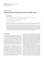
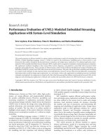
Analytical expressions for
{μ
p
}
4
p
=1
in the pure LOS case
are found by employing (37)in(36). The square roots of
the eigenvalues (i.e., singular values of H
LOS
)areplottedas
afunctionof
|β
1
|=|β
2
| in Figure 5. The lines represent
the analytical expressions, while the circles are determined
by using a numerical procedure to find the singular values
when the exact path length from (15) is employed in H
LOS
.
The parameters used in the exact path length case are as fol-
lows: φ
V
= π/2, α
U
= π, α
V
= π, R = 500 m, d
(1)
U
= 1m,
d
(2)
U
= 1m,λ = 0.03 m, while d
(1)
V
and d
(2)
V
are chosen to get
the correct values of
|β
1
| and |β
2
|.
The figure shows that there is a perfect agreement be-
tween the analytical singular values based on approximate
path lengths from (16), and the singular values found based
onexactpathlengthsfrom(15). We see how the singular
values spread out as the design deviates further and further
from the optimal ( decreasing
|β
i
|), and for small |β
i
|,weget
rank(H
LOS
) = 1, which we refer to as a total design mis-
match. In the figure, the solid line in the middle represents
two singular values, as they become identical in the present
case (
|β
1
|=|β
2
|). This is easily verified by observing the
−20 −15 −10 −50 510
|β
1
|=|β
2
| (dB)
0
0.5
1
1.5
2
2.5
3
3.5
4
Singular values of H
LOS
,
√
μ
i
u
(1)
1
u
(2)
1
u
(1)
2
u
(2)
2
u
(1)
1
u
(2)
2
and u
(1)
2
u
(2)
1
Numerical
Represents two
singular values
Figure 5: The singular values of H
LOS
for the 4 × 4 MIMO system
as a function of
|β
1
|=|β
2
|, both exactly found by a numerical pro-
cedure and the analytical from Section 5.
symmetry in the analytical expressions for the eigenvalues.
For
|β
i
| > 1, we experience some kind of periodic behavior;
this is due to the fact that (24) has more than one solution.
However, in this paper, we introduced a size requirement
on the arrays, thus we concentrate on the solutions where
|β|≤1.
When K
=∞in (4), the MI from (2)becomesaran-
dom variable. We char acterize the random MI by the MI cu-
mulative distribution function (CDF), which is defined as the
probability that the MI falls below a given threshold, that is,
F(I
th
) = Pr[I < I
th
][5]. All CDF curves plotted in the next
figures are based on 50 000 channel realizations.
We start by illustrating the combined influence of
|β
i
|
and the Ricean K-factor. In Figure 6, we show F(I
th
) for the
optimal design case (
|β
1
|=|β
2
|=0 dB), and for the total
design mismatch (
|β
1
|=|β
2
|=−30 dB).
The figure shows that the design of the URAs becomes
more and more important as the K-factor increases. This is
because it increases the influence of H
LOS
on H (cf. (4)). We
also observe that the MI increases for the optimal design case
when the K-fac tor increases, while the MI decreases for in-
creasing K-factors in the total design mismatch case. This
illustrates the fact that the pure LOS case outperforms the
uncorrelated Rayleigh case when we do optimal array design
(i.e., orthogonal LOS subchannels).
In Figure 7,weillustratehowF(I
th
)changeswhenwe
have different combinations of the two
|β
i
|. We see how the
MI decreases when
|β
i
| decreases. In this case, the Ricean K-
factor is 5 dB, and from Figure 6, we know that the MI would
be even more sensitive to
|β
i
| for larger K-factors. From the
figure, we observe that even with some deviation from the
Frode Bøhagen et al. 9
46810121416
I
th
(bps/Hz)
0
0.1
0.2
0.3
0.4
0.5
0.6
0.7
0.8
0.9
1
F(I
th
)
|β
1
|=|β
2
|=−30 dB
|β
1
|=|β
2
|=0dB
K = 20 dB
K
= 10 dB
K
=−5dB
K
=−5dB
K
= 10 dB
K
= 20 dB
Figure 6: The MI C DF for the 4×4 MIMO system when γ = 10 dB.
6 7 8 9 10 11 12 13 14 15
I
th
(bps/Hz)
0
0.1
0.2
0.3
0.4
0.5
0.6
0.7
0.8
0.9
1
F(I
th
)
|β
1
|=|β
2
|=0dB(optimal)
|β
1
|=−3dBand|β
2
|=0dB
|β
1
|=|β
2
|=−3dB
|β
1
|=|β
2
|=−20 dB
Rayleigh (K
=−∞dB)
Figure 7: The MI CDF for the 4×4 MIMO system when γ = 10 dB
and K
= 5 dB (except for the Rayleigh channel where K =−∞dB).
optimal design, we get higher MI compared to the case of
uncorrelated Rayleigh subchannels.
7. CONCLUSIONS
Basedonthenewgeneralgeometricalmodelintroducedfor
the uniform rectangular array (URA), which also incorpo-
rates the uniform linear array (ULA), we have investigated
the optimal design for line-of-sight (LOS) channels with re-
spect to mutual information for all possible combinations of
URA and ULA at transmitter and receiver. The optimal de-
sign based on correct separation between the antennas (d
U
and d
V
) is possible in several interesting cases. Important
parameters with respect to the optimal design are the wave-
length, the transmission distance, and the array dimensions
in the plane perpendicular to the transmission direction.
Furthermore, we have characterized and investigated the
consequence of nonoptimal design, and in the genera l case,
we gave simplified expressions for the pure LOS eigenvalues
as a function of the design parameters. In addition, we de-
rived explicit analytical expressions for the eigenvalues for
some interesting cases.
ACKNOWLEDGMENTS
This work was funded by Nera with support from the Re-
search Council of Norway (NFR), and partly by the BEATS
project financed by the NFR, and the NEWCOM Network
of Excellence. Some of this material was presented at the
IEEE Signal Processing Advances in Wireless Communica-
tions (SPAWC), Cannes, France, July 2006.
REFERENCES
[1] G. J. Foschini and M. J. Gans, “On limits of wireless commu-
nications in a fading environment when using multiple an-
tennas,” Wireless Personal Communications,vol.6,no.3,pp.
311–335, 1998.
[2] E. Telatar, “Capacity of multiantenna Gaussian channels,”
Tech. Memo, AT&T Bell Laboratories, Murray Hill, NJ, USA,
June 1995.
[3] T. Kaiser, “When will smart antennas be ready for the market?
Part I,” IEEE Signal Processing Magazine, vol. 22, no. 2, pp. 87–
92, 2005.
[4] T. Kaiser, “When will smart antennas be ready for the mar-
ket? Part II—results,” IEEE Signal Processing Magazine, vol. 22,
no. 6, pp. 174–176, 2005.
[5] D. Gesbert, M. Shafi, D S. Shiu, P. J. Smith, and A. Naguib,
“From theory to practice: an overview of MIMO space-time
coded wireless systems,” IEEE Journal on Selected Areas in
Communications, vol. 21, no. 3, pp. 281–302, 2003.
[6] D. Gesbert, “Multipath: curse or blessing? A system perfor-
mance analysis of MIMO wireless systems,” in Proceedings
of the International Zurich Seminar on Communications (IZS
’04), pp. 14–17, Zurich, Switzerland, February 2004.
[7] P. F. Driessen and G. J. Foschini, “On the capacit y formula for
multiple input-multiple output wireless channels: a geometric
interpretation,” IEEE Transactions on Communications, vol. 47,
no. 2, pp. 173–176, 1999.
[8]F.Bøhagen,P.Orten,andG.E.Øien,“Designofoptimal
high-rank line-of-sight MIMO channels,” IEEE Transactions
on Wireless Communications, vol. 6, no. 4, pp. 1420–1425,
2007.
[9] F.Bøhagen,P.Orten,andG.E.Øien,“Constructionandca-
pacity analysis of high-rank line-of-sight MIMO channels,” in
Proceedings of the IEEE Wireless Communications and Network-
ing Conference (WCNC ’05), vol. 1, pp. 432–437, New Orleans,
La, USA, March 2005.
[10] P. Larsson, “Lattice array receiver and sender for spatially or-
thonormal MIMO communication,” in Proceedings of the IEEE
61st Vehicular Technology Conference (VTC ’05), vol. 1, pp.
192–196, Stockholm, Sweden, May 2005.
10 EURASIP Journal on Wireless Communications and Networking
[11] F. Bøhagen, P. Orten, and G. E. Øien, “On spherical vs. plane
wave modeling of line-of-sight MIMO channels,” to appear in
IEEE Transactions on Communications.
[12] H. Xu, M. J. Gans, N. Amitay, and R. A. Valenzuela, “Exper-
imental verification of MTMR system capacity in controlled
propagation environment,” Electronics Letters, vol. 37, no. 15,
pp. 936–937, 2001.
[13] J S. Jiang and M. A. Ingram, “Spherical-wave model for short-
range MIMO,” IEEE Transactions on Communications, vol. 53,
no. 9, pp. 1534–1541, 2005.
[14] D. Hosli and A. Lapidoth, “How good is an isotropic Gaussian
input on a MIMO Ricean channel?” in Proceedings IEEE Inter-
national Symposium on Information Theory ( ISIT ’04), p. 291,
Chicago, Ill, USA, June-July 2004.
[15] G. L. St
¨
uber, Principles of Mobile Communication,KluwerAca-
demic Publishers, Norwell, Mass, USA, 2nd edition, 2001.
[16] L. R
˚
ade and B. Westergren, Mathematics Handbook for Science
and Engineering, Springer, Berlin, Germany, 5th edition, 2004.
[17] D. Tse and P. Viswanath, Fundamentals of Wireless Communi-
cation, Cambridge University Press, Cambridge, UK, 1st edi-
tion, 2005.
[18] IEEE 802.16-2004, “IEEE standard for local and metropolitan
area networks part 16: air interface for fixed broadband wire-
less access systems,” October 2004.