Báo cáo hóa học: "Research Article Interference Mitigation in Cooperative SFBC-OFDM" potx
Bạn đang xem bản rút gọn của tài liệu. Xem và tải ngay bản đầy đủ của tài liệu tại đây (829.17 KB, 11 trang )
Hindawi Publishing Corporation
EURASIP Journal on Advances in Signal Processing
Volume 2008, Article ID 125735, 11 pages
doi:10.1155/2008/125735
Research Article
Interference Mitigation in Cooperative SFBC-OFDM
D. Sreedhar and A. Chockalingam
Department of Electrical Communication Engineering, Indian Institute of Science, Bangalore 560012, India
Correspondence should be addressed to A. Chockalingam,
Received 15 November 2007; Accepted 28 March 2008
Recommended by Andrea Conti
We consider cooperative space-frequency block-coded OFDM (SFBC-OFDM) networks with amplify-and-forward (AF) and
decode-and-forward (DF) protocols at the relays. In cooperative SFBC-OFDM networks that employ DF protocol, (i), intersymbol
interference (ISI) occurs at the destination due to violation of the “quasistatic” assumption because of the frequency selectivity of
the relay-to-destination channels, and (ii) intercarrier interference (ICI) occurs due to imperfect carrier synchronization between
the relay nodes and the destination, both of which result in error-floors in the bit-error performance at the destination. We propose
an interference cancellation algorithm for this system at the destination node, and show that the proposed algorithm effectively
mitigates the ISI and ICI effects. In the case of AF protocol in cooperative networks (without SFBC-OFDM), in an earlier work, we
have shown that full diversity can be achieved at the destination if phase compensation is carried out at the relays. In cooperative
networks using SFBC-OFDM, however, this full-diversity attribute of the phase-compensated AF protocol is lost due to frequency
selectivity and imperfect carrier synchronization on the relay-to-destination channels. We propose an interference cancellation
algorithm at the destination which alleviates this loss in performance.
Copyright © 2008 D. Sreedhar and A. Chockalingam. This is an open access article distributed under the Creative Commons
Attribution License, which permits unrestricted use, distribution, and reproduction in any medium, provided the original work is
properly cited.
1. INTRODUCTION
Cooperative communications have become popular in recent
research, owing to the potential for several benefits when
communicating nodes in wireless networks are allowed to
cooperate [1]. A classical benefit that arises from cooperation
among nodes is the possibility of achieving spatial diversity,
even when the nodes have only one antenna. That is,
cooperation allows single-antenna nodes in a multiuser
environment to share their antennas with other nodes in a
distributed manner so that a given node can realize a virtual
multiantenna transmitter that provides transmit diversity
benefits. Such techniques, termed as “cooperative diversity”
techniques, have widely been researched [2, 3]. Achieving
cooperative diversity benefits based on a relay node merely
repeating the information sent by a source node comes at the
price of loss of throughput because the relay-to-destination
transmission requires a separate time slot [3]. This loss
in throughput due to repetition-based cooperation can be
alleviated by integrating channel coding with cooperation
[4]. Also, cooperation methods using distributed space-time
coding are widely being researched [5, 6].
Recent investigations on cooperative communications
focus on space-time cooperative systems based on OFDM
[7–11]. Since space-time codes were developed originally
for frequency-flat channels, an effective way to use them
on frequency selective channels is to use them along with
OFDM. A major advantage of space-time OFDM (ST-
OFDM) is that a frequency selective channel is converted
into multiple frequency flat channels [12], and with a
proper outer code applied along with ST-OFDM code as
an inner code, the full diversity of a frequency selective
channel (i.e., multipath diversity) can be exploited as well.
In addition to multipath diversity, user-cooperation diversity
can be achieved in cooperative ST-OFDM (CO-ST-OFDM)
systems, where space-time block codes (STBC) can be
used in the relaying phase of cooperation [7, 8]. Accurate
time and frequency synchronization, however, are crucial
in achieving the promised potential of CO-ST-OFDM [8–
11]. For example, in the context of cooperative OFDM,
the relays-to-destination transmissions during the relaying
phase of the protocol resemble transmissions from multiple
noncooperating users in an upink OFDMA system [13, 14].
Hence nonzero carrier frequency offsets (CFOs) arising due
2 EURASIP Journal on Advances in Signal Processing
to imperfect carrier synchronization between the relays and
the destination results in multiuser interference (multiple
relays viewed as virtual multiple users) at the destination.
A similar effect will occur if the timing synchronization
is imperfect, that is, with nonzero timing offset. Without
any effort to handle this interference, the performance of
cooperative OFDM may end up being worse than that of
OFDM without cooperation, particularly when the synchro-
nization errors (in terms of CFOs and timing offsets) are
large, and hence interference cancellation (IC) techniques
employed at the destination will be of interest. Equalization
techniques to alleviate the effect of carrier frequency offsets
in distributed STBC-OFDM have been reported in the
literature [10]. Practical timing and frequency synchro-
nization algorithms and channel estimation for CO-ST-
OFDM using Alamouti code [15]havebeeninvestigatedin
[8].
An alternate way to employ space-time codes in MIMO
OFDM is to perform coding across space and frequency
(instead of coding across space and time), which is often
referred to as space-frequency coding (SFC) [16–19]. One
way to do space-frequency coding is to take space-time codes
and apply them in frequency dimension instead of time
dimension [16]. The advantages of using space-frequency
codes along with OFDM are low delays and robustness to
time-selectivity of the channel [19]. Our focus, accordingly,
in this paper is on cooperative OFDM systems when space-
frequency block codes (SFBC) are employed; we refer to these
systems as cooperative SFBC-OFDM (CO-SFBC-OFDM)
systems.
Our new contribution in this paper can be highlighted as
follows. In CO-SFBC-OFDM networks that employ decode-
and-forward (DF) protocol, (i) intersymbol interference
(ISI) occurs at the destination due to violation of the
“quasistatic” assumption because of the frequency selectivity
of the relay-to-destination channels, and (ii) intercarrier
interference (ICI) occurs due to imperfect carrier synchro-
nization between the relay nodes and the destination, both
of which result in errorfloors in the bit error performance
at the destination. We propose an interference cancellation
algorithm for this system at the destination node, and
show that the proposed algorithm effectively mitigates the
ISI and ICI effects. In the case of amplify-and-forward
(AF) protocol in cooperative networks (without SFBC-
OFDM), in our earlier work in [20], we have shown that
full diversity can be achieved at the destination if phase
compensation is carried out at the relays. In cooperative
networks using SFBC-OFDM, however, this full-diversity
attributeofthephase-compensatedAFprotocolislostdue
to frequency selectivity and imperfect carrier synchroniza-
tion on the relay-to-destination channels. To address this
problem, we propose an interference cancellation algorithm
at the destination which alleviates this loss in perfor-
mance.
The rest of this paper is organized as follows. In Section 2,
we present the CO-SFBC-OFDM system model with AF
protocol and phase compensation at the relays, and illustrate
the ISI and ICI effects. The proposed IC algorithm for this
system is presented in Section 2.2. Section 3 presents the
R
1
R
2
R
N
.
.
.
SD
H
(i)
s
1
H
(i)
s
2
H
(i)
s
N
H
(i)
r
1
,
1
H
(i)
r
2
,
2
H
(i)
r
N
,
N
OFDM broadcast
(phase 1)
SFBC relaying
(phase 2)
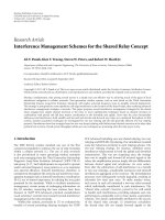
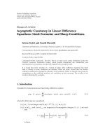
Figure 1: A cooperative SFBC-OFDM network consisting of one
source, one destination, and N relays.
system model for CO-SFBC-OFDM system with DF protocol
at the relays, and illustrates the associated ISI and ICI effects.
The proposed IC algorithm for this DF protocol system is
presented in Section 3.2. Results and discussions for both AF
and DF protocols are presented in Section 4. Conclusions are
given in Section 5.
2. COOPERATIVE SFBC-OFDM WITH AF PROTOCOL
Consider a wireless network as depicted in Figure 1 with N+2
nodes consisting of a source, a destination and N relays.
All nodes are half duplex nodes, that is, a node can either
transmit or receive at a time. OFDM is used for transmission
on the source-to-relays and relays-to-destination links. The
destination is assumed to know (i) source-to-relays channel
state information (CSI) and (ii) relays-to-destination CSI.
Each relay is assumed to know the phase information of the
channel from the source to itself. We employ amplification
and channel phase compensation on the received signals
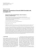
at the relays. The transmission protocol is as follows (see
Figures 1 and 2):
(i) In the first time slot (i.e., phase 1), the source
transmits information symbols X
(k)
,1≤ i ≤ M using
an M subcarrier OFDM symbol. All the N relays
receive this OFDM symbol. This phase is called the
OFDM broadcast phase.
(ii) In the second time slot (i.e., phase 2), N relays
forward the received information. (We assume that
all the relays participate in the cooperative trans-
mission. It is also possible that some relays do not
participate in the transmission based on whether
the channel state is in outage or not. We do not
consider such a partial participation scenario here.)
For the AF protocol, the relays perform channel phase
compensation and amplification on the received
signal, followed by space-frequency block coding.
This phase is called AF-SFBC relay phase. The desti-
nation receives these transmissions, performs ICI/ISI
cancellation and SFBC decoding.
D. Sreedhar and A. Chockalingam 3
Tx
Rx
S transmits OFDM symbol
x
= [X
(1)
X
(2)
X
(M)
]
on M subcarriers
Each relay transmits an
SFBC encoded vector
c
rj
,1≤ j ≤ N
Phase 1 Phase 2
Time
Relays R
1
, R
2
, , R
N
decode/amplify the
received signal from S
Destination performs
ICI/ISI cancellation and
SFBC decoding
Phase 1 Phase 2
Time
Figure 2: AF/DF transmission protocol in a cooperative SFBC-
OFDM network.
Broadcast reception at the relays
Let x
= [X
(1)
, X
(2)
, , X
(M)
] denote the information symbol
vector transmitted by the source on M subcarriers. (We use
the following notation in this paper: Bold letter uppercase is
used to represent matrices and bold letter lower case is used
to represent vectors. R(
·) denotes real value of a complex
argument and I(
·) denotes imaginary value. x
(I)
and x
(Q)
denote the real and imaginary parts of the complex number
x.(
·)
H
and (·)
T
denote matrix conjugate transposition
and matrix transposition, respectively. (
·)
∗
denotes matrix
conjugation. diag
{a
1
, a
2
, , a
N
} is a diagonal matrix having
diagonal entries a
1
, a
2
, , a
N
. j denotes
√
−1. E{·} denotes
expectation operation.) The received signal, v
(k)
rj
, on the kth
subcarrier at the jth relay during the OFDM broadcast phase
can be written as
v
(k)
rj
=
E
1
H
(k)
sj
X
(k)
+ Z
(k)
rj
,1≤ i ≤ M,1≤ j ≤ N,(1)
where H
(k)
sj
is the frequency response on the kth subcarrier
of the channel from source to jth relay, given by H
(k)
sj
=
DFT
M
(h
(n)
sj
), where h
(n)
sj
is the time-domain impulse response
of the channel from source to jth relay. (In all the source-
to-relay and relay-to-destination links, we assume frequency-
selective block fading channel model [21, 22]. The maximum
delay spread of the channel is assumed to be less than the
added guard interval. The channel is assumed to be static for
one OFDM symbol duration.) Z
(k)
rj
is additive white Gaussian
noise with zero mean and variance σ
2
,andE{|X
(k)
|
2
}=1.
E
1
is the energy per symbol spent in the broadcast phase. On
the source-to-relay links, all the relays listen to the source and
each relay can compensate for its CFO individually. Hence
there is no ISI/ICI on the source-to-relay links.
Space-frequency block coding at the relay in AF protocol
At the relay j, first, phase compensation followed by an
amplification of the received signal is done. Let H
(k)
sj
=
|
H
(k)
sj
|e
jθ
(k)
sj
. The operation at the relay can then be described
as (i) phase compensation (i.e, multiplication by e
−jcθ
(k)
sj
), and
(ii) amplification on v
(k)
rj
such that energy per transmission is
E
2
, that is,
v
(k)
rj
=
E
2
E
1
+ σ
2
e
−jθ
(k)
sj
v
(k)
rj
,
(2)
=
E
1
E
2
E
1
+ σ
2
H
(k)
sj
X
(k)
+
Z
(k)
rj
,
(3)
where
Z
(k)
rj
=
E
2
E
1
+ σ
2
e
−jθ
(k)
sj
Z
(k)
rj
. (4)
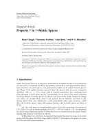
The space-frequency block encoding at the relays is illus-
trated in Figure 3.AnN
× K space-time block code (STBC)
matrix with P information symbols is used across subcarriers
in N-relays. For the AF-SFBC relay phase transmission, we
divide the M subcarriers into M
g
groups such that M =
M
g
K+κ.IfM is not a multiple of K then, there will not be any
transmission on κ subcarriers, and accordingly the source
will transmit only M
g
P information symbols and there will
be no transmission on M
−M
g
P subcarriers from the source.
Note that M
g
P ≤ M since P/K ≤ 1 for the STBC codes
considered. Now, for each relay j,weformM
g
groups out
of the M
g
P values in v
(k)
rj
, and, for each group q, we form the
2P
×1vectorv
(q)
rj
,givenby
v
(q)
rj
=
v
((q−1)P+1)(I)
rj
, v
((q−1)P+1)(Q)
rj
, v
((q−1)P+2)(I)
rj
, v
((q−1)P+2)(Q)
rj
,
···v
(qP)(I)
rj
, v
(qP)(Q)
rj
T
.
(5)
The space-frequency coded symbols for the qth group of the
jth relay can be obtained as
c
(q)
rj
= A
j
v
(q)
rj
=
E
1
E
2
E
1
+ σ
2
A
j
H
(q)
sj
x
(q)
+ A
j
z
(q)
rj
,1≤ q ≤ M
g
,
(6)
where the 2P
× 2P matrix H
(q)
sj
= diag[|H
((q−1)P+1)
sj
|,
|H
((q−1)P+1)
sj
|, , |H
(qP)
sj
|, |H
(qP)
sj
|], the 2P × 1vectorz
(q)
rj
= [
Z
((q−1)P+1),(I)
rj
,
Z
((q−1)P+1),(Q)
rj
, ,
Z
(qP),(I)
rj
,
Z
(qP),(Q)
rj
]
T
,and
the 2P
× 1vectorx
(q)
= [X
((q−1)P+1),(I)
, X
((q−1)P+1),(Q)
, ,
X
(qP),(I)
, X
(qP),(Q)
]
T
.TheA
j
matrices perform the space-
frequency encoding. For example, for the 2-relay case (i.e.,
N
= 2) using Alamouti code:
A
1
=
10j 0
0
−10j
, A
2
=
010j
10j 0
. (7)
4 EURASIP Journal on Advances in Signal Processing
M subcarrier OFDM symbol at the relay
N
×K
STBC matrix
123
123
123
M
M
M
···
···
···
.
.
.
.
.
.
.
.
.
.
.
.
.
.
.
IDFT
IDFT
IDFT
GI
GI
GI
R
1
R
2
R
N
Figure 3: Space-frequency block coding at the relays.
The overall space-frequency coded symbol vector from the
jth relay can be written as
c
rj
=
⎡
⎢
⎢
⎢
⎢
⎢
⎢
⎢
⎣
c
(1)
rj
.
.
.
c
(M
g
)
rj
0
κ×1
⎤
⎥
⎥
⎥
⎥
⎥
⎥
⎥
⎦
. (8)
Finally, the inverse Fourier transform of c
rj
, that is, t
rj
=
IDFT(c
rj
) is transmitted by the jth relay.
Received signal at the destination
The received time-domain baseband signal at the desti-
nation, after coarse carrier frequency synchronization and
guard time removal, is given by
y
(n)
=
N
j=1
t
(n)
rj
h
(n)
jd
e
j2π
j
n/N
+ z
(n)
d
,0≤ n ≤ M − 1,
(9)
where denotes linear convolution, h
n
jd
is the channel
impulse response from the jth relay to the destination. It is
assumed that h
n
jd
is nonzero only for n = 0, , L − 1, where
L is the maximum channel delay spread. It is also assumed
that the added guard interval is greater than L.
j
, j =
1, N,0≤|
j
|≤0.5, denotes residual carrier frequency
offset (CFO) from the jth relay normalized by the subcarrier
spacing, and z
(n)
d
is the AWGN with zero mean and variance
σ
2
d
. We assume that all the nodes are time synchronized and
that
j
, j = 1, , N are known at the destination. At the
destination, y
(n)
is first fed to the DFT block. The M ×1DFT
output vector, y, can be written in the form
y
=
N
j=1
Ψ
j
H
jd
c
rj
+ z
d
, (10)
where Ψ
j
is a M × M circulant matrix given by
Ψ
j
=
⎡
⎢
⎢
⎢
⎢
⎢
⎢
⎢
⎢
⎣
ψ
(0)
j
ψ
(1)
j
··· ψ
(M−1)
j
ψ
(M−1)
j
ψ
(0)
j
··· ψ
(M−2)
j
.
.
.
.
.
.
.
.
.
.
.
.
ψ
(1)
j
ψ
(2)
j
··· ψ
(0)
j
⎤
⎥
⎥
⎥
⎥
⎥
⎥
⎥
⎥
⎦
, (11)
where
ψ
(k)
j
= DFT
M
e
j2πn
j
/M
. (12)
H
jd
is the M × M diagonal channel matrix given by H
jd
=
diag[H
(1)
jd
, H
(2)
jd
, , H
(M)
jd
], and the channel coefficient in
frequency domain H
(k)
jd
is given by H
(k)
jd
= DFT
M
(h
(n)
jd
). Sim-
ilarly, z
d
= [Z
(1)
d
, Z
(2)
d
, , Z
(M)
d
], where Z
(k)
d
= DFT
M
(z
(n)
d
).
Equation (10)canberewrittenas
y
=
N
j=1
ψ
(0)
j
H
jd
c
rj
+
N
j
=1
Ψ
j
−ψ
(0)
j
I
H
jd
c
rj
ICI
+ z
d
. (13)
If we collect the K entries of y corresponding to the qth SFBC
block and form a K
×1vectory
(q)
, then we can write
y
(q)
=
N
j=1
ψ
(0)
j
H
(q)
jd
c
(q)
rj
+
N
j=1
Ψ
j
−ψ
(0)
j
I
[q]
H
jd
c
rj
+ z
(q)
d
,
(14)
where H
(q)
jd
=diag[H
((q−1)K+1)
jd
, , H
(qK)
jd
], z
(q)
d
=[Z
((q−1)K+1)
d
,
, Z
(qK)
d
]
T
and (·)
[q]
denotes picking the K rows of a matrix
starting from (q
−1)K +1.
D. Sreedhar and A. Chockalingam 5
Optimal ML detector and zero-forcing detector
Using (6), the c
rj
vector in (8)canbewrittenas
c
rj
=
E
1
E
2
E
1
+ σ
2
⎡
⎢
⎢
⎢
⎢
⎢
⎢
⎢
⎢
⎢
⎢
⎣
A
j
H
(1)
sj
0 ··· 00
0A
j
H
(2)
sj
··· 00
.
.
. 0
.
.
.
.
.
.
.
.
.
00
··· A
j
H
(M
g
)
sj
0
00
··· 00
⎤
⎥
⎥
⎥
⎥
⎥
⎥
⎥
⎥
⎥
⎥
⎦
Ω
j
⎡
⎢
⎢
⎢
⎢
⎢
⎢
⎢
⎢
⎢
⎣
x
(1)
x
(2)
.
.
.
x
(M
g
)
0
⎤
⎥
⎥
⎥
⎥
⎥
⎥
⎥
⎥
⎥
⎦
x
+
⎡
⎢
⎢
⎢
⎢
⎢
⎢
⎢
⎢
⎢
⎢
⎣
A
j
z
(1)
rj
A
j
z
(2)
rj
.
.
.
A
j
z
(M
g
)
rj
0
⎤
⎥
⎥
⎥
⎥
⎥
⎥
⎥
⎥
⎥
⎥
⎦
η
j
.
(15)
Substituting this in (10), we get
y
=
N
j
=1
Ψ
j
H
jd
Ω
j
Φ
x
+
N
j=1
Ψ
j
H
jd
η
j
+ z
d
. (16)
The optimal ML detection of
x
is given by
x = arg min
x
(
y
−Φ
x
)
H
Σ
−1
(
y
−Φ
x
), (17)
where Σ is the covariance matrix of
N
j
=1
Ψ
j
H
jd
η
j
+ z
d
. This
has complexity of the order O(M
M/KP
), where M is the
cardinality of the signal set used. A suboptimal zero-forcing
detection can be carried out using
y =
Φ
H
Φ
−1
Φ
H
y.
(18)
Since Φ is of size M
× M, the inversion operation is of
complexity O(M
4
). Interference cancellers at much lesser
complexity can be adopted for the detection. In the fol-
lowing, we formulate the proposed ISI-ICI cancellation
approach.
Detection in frequency-flat channel in the absence of CFO
For a frequency-flat channel, all the diagonal entries of H
(q)
sj
and H
(q)
jd
become equal. Hence in frequency-flat channel with
no CFO, (14)reducesto
y
(q)
=
N
j=1
H
((q−1)2P+1)
sj
H
((q−1)K+1)
jd
A
j
x
(q)
+
N
j=1
A
j
z
(q)
rj
+ z
(q)
d
.
(19)
Define H
(q)
eq
=
N
j=1
|H
((q−1)2P+1)
sj
|H
((q−1)K+1)
jd
A
j
. It can then
be verified from the results in [20] that R(H
(q)
eq
H
H
(q)
eq
)is
a block diagonal matrix, and hence with the operation
R(H
(q)
eq
H
y
(q)
) it is possible to do full-diversity symbol-by-
symbol detection of y
(q)
.Butwhenthechannelisfrequency-
selective and CFOs are nonzero, this detection gives rise
to ISI and ICI, which we will analyze in the following
Section 2.1.
2.1. ICI and ISI in AF protocol
Now we analyze the ICI and ISI at the output of the
detection scheme described in Section 2, when the relays-to-
destination channels as well as the source-to-relays channels
are frequency-selective and when CFOs are not equal to zero.
Define
H
(q)
eq-af
=
N
j=1
E
1
E
2
E
1
+ σ
2
ψ
(0)
j
H
((q−1)2P+1)
sj
H
((q−1)K+1)
jd
A
j
.
(20)
Since
E
1
E
2
/(E
1
+ σ
2
)ψ
(0)
j
is a scalar, it is easily verified from
the results in [20] that R(H
(q)
eq-af
H
H
(q)
eq-af
) is a block diagonal
matrix. Next, we split the channel matrices H
(q)
sj
and H
(q)
jd
into
a quasistatic part and a nonquasistatic part, as
H
(q)
sj
=
H
((q−1)2P+1)
sj
I
H
(q)
sj,qs
+
⎡
⎢
⎢
⎢
⎢
⎢
⎣
00··· 0
0 V
··· 0
.
.
.
.
.
.
.
.
.
.
.
.
00
···
H
(q2P)
sj
−
H
((q−1)2P+1)
sj
⎤
⎥
⎥
⎥
⎥
⎥
⎦
H
(q)
sj,nqs
,
H
(q)
jd
= H
((q−1)K+1)
jd
I
H
(q)
jd,qs
+
⎡
⎢
⎢
⎢
⎢
⎢
⎢
⎣
00··· 0
0 S
··· 0
.
.
.
.
.
.
.
.
.
.
.
.
00
··· H
(qK)
jd
−H
((q−1)K+1)
jd
⎤
⎥
⎥
⎥
⎥
⎥
⎥
⎦
H
(q)
jd,nqs
,
(21)
where V denotes
|H
((q−1)2P+2)
sj
|−|H
((q−1)2P+1)
sj
|
,andS de-
notes H
((q−1)K+2)
jd
−H
((q−1)K+1)
jd
.
6 EURASIP Journal on Advances in Signal Processing
Using this, the output of the operation R
H
(q)
eq-af
H
y
(q)
on (14)canbewrittenas
y
(q)
= R
H
(q)
eq-af
H
H
(q)
eq-af
x
(q)
Signal part
+ R
H
(q)
eq-af
H
N
j
=1
ψ
(0)
j
W
ISI due to frequency-selectivity
of broadcast and relay channels
x
(q)
+ R
H
(q)
eq-af
H
N
j
=1
(Ψ
j
−ψ
(0)
j
I
)
[q]
H
jd
c
rj
ICI due to CFOs
+ R
H
(q)
eq-af
H
N
j
=1
A
j
z
(q)
rj
+ z
(q)
d
Total noise
,
(22)
where W denotes that (
H
(q)
jd,nqs
A
j
H
(q)
sj,qs
+ H
(q)
jd,qs
A
j
H
(q)
sj,nqs
+
H
(q)
jd,nqs
A
j
H
(q)
sj,nqs
).
As pointed out earlier, the optimum detector in this
case would be a joint maximum-likelihood detector in
PM
g
variables, which has a prohibitive exponential receiver
complexity.
2.2. Proposed ISI-ICI cancelling detector
for AF protocol
In this section, we propose a two-step parallel interfer-
ence canceling (PIC) receiver that cancels the frequency-
selectivity-induced ISI, and the CFO-induced ICI. The
proposed detector estimates and cancels the ISI (caused due
to the violation of the quasistatic assumption) in the first
step, and then estimates and cancels the ICI (caused due
to loss of subcarrier orthogonality because of CFO) in the
second step. This two-step procedure is then carried out in
multiple stages. The proposed detector is presented in the
following.
As can be seen, (22) identifies the desired signal, ISI,
ICI, and noise components present in the output
y
(q)
.Based
on this received signal model and the knowledge of the
matrices H
(q)
jd,nqs
, H
(q)
jd,qs
, H
(q)
sj,nqs
, H
(q)
sj,qs
,andH
(q)
eq-af
,forall
q, j we formulate the proposed interference estimation and
cancellation procedure as follows.
(1) For each space-frequency code block q, estimate the
information symbols
x
(q)
from (22), ignoring ISI and
ICI.
(2) For each space-frequency code block q,obtainan
estimate of the ISI (i.e., an estimate of the ISI term in
(22)) from the estimated symbols
x
(q)
in the previous
step.
(3) Cancel the estimated ISI from
y
(q)
.
(4) Using
x
(q)
from step 1, regenerate c
(q)
using (6). Then,
using
c
(q)
, obtain an estimate of the ICI (i.e., an
estimate of the ICI term in (22)).
(5) Cancel the estimated ICI from the ISI-canceled
output in step 3.
(6) Take the ISI- and ICI-canceled output from step 5
as the input back to step 1 (for the next stage of
cancellation).
Based on the above, and Λ
(q)
af
= R(H
(q)
eq-af
H
H
(q)
eq-af
), the
cancellation algorithm for the mth stage can be summarized
as in Algorithm 1.
It is noted that Algorithm 1 has polynomial complexity.
Also, Λ
(q)
af
is a full-rank block diagonal matrix, and its
inversion in the second equation in Algorithm 1 is simple.
Assuming that the multiplication of the matrices A
j
with
H
sj
, H
jd
could be precomputed, the total number of complex
multiplications required for m stages of the proposed
iterative interference cancellation is 2P
M/K(K +2P +(m−
1)(4P +2K + NK)),whichismuchlesscomplexthanthe
zero-forcing detector complexity of O(M
4
).
3. COOPERATIVE SFBC-OFDM WITH DF PROTOCOL
The broadcast phase of the transmission protocol is the same
for both AF protocol as well as DF protocol. In the relay
phase of the DF protocol, however, the relays decode the
information (instead of merely amplifying it) sent by the
source, and transmits a space-frequency encoded version of
this decoded information. This phase is called DF-SFBC relay
phase. The destination receives this transmission, does ISI
and ICI cancellation, followed by SFBC decoding.
Space-frequency block coding at the relay in DF protocol
We employ the same space-frequency encoding strategy as
in AF protocol, except that instead of an amplification
operation in (2) at the relay j, a decoding of the information
symbols is done, that is, the decoded symbol on the kth
subcarrier at the jth relay, denoted by
X
(k)
j
, is obtained as
X
(k)
j
=
E
2
arg min
X
(k)
v
(k)
rj
−
E
1
H
(k)
sj
X
(k)
2
,
1
≤ i ≤ M
g
P,1≤ j ≤ N,
(23)
where E
2
is the energy per transmission in the relay phase.
The corresponding space-frequency coded symbols for the
qthgroupofsubcarriersofthejth relay is obtained as
c
(q)
rj
= A
j
x
(q)
j
, (24)
where
x
(q)
j
= [
X
((q−1)P+1), (I)
j
,
X
((q−1)P+1),(Q)
j
, ,
X
(qP), (I)
j
,
X
(qP),(Q)
j
]
T
. The received signal model at the destination in
the DF protocol is the same as in (14), with c
(q)
rj
generated
as in (24). It is possible that the symbol vector x is detected
differently at each relay. For the purpose of developing the IC
algorithm, however, and henceforth in this paper, we assume
that
x
(q)
j
= x
(q)
k
∀j, k and drop the j index from x
(q)
j
.Inall
our simulations, however, we will use the actual
x
(q)
j
’s at the
relays.
D. Sreedhar and A. Chockalingam 7
Initialization: Set m = 1.
Evaluate
y
(q,m)
= R
H
(q)
eq-af
H
y
(q)
,1≤ q ≤ M
g
.
Loop
Estimate
x
(q,m)
=
Λ
(q)
af
−1
y
(q,m)
,1≤ q ≤ M
g
.
Cancel ISI
y
(q,m+1)
=
y
(q,1)
−R
H
(q)
eq-af
H
N
j=1
ψ
(0)
j
H
(q)
jd,nqs
A
j
H
(q)
sj,qs
+ H
(q)
jd,qs
A
j
H
(q)
sj,nqs
+ H
(q)
jd,nqs
A
j
H
(q)
sj,nqs
x
(q,m)
,
1
≤ q ≤ M
g
.
Form
c
(q,m)
rj
from
c
(q,m)
rj
=
E
1
E
2
E
1
+ σ
2
A
j
H
(q)
sj
x
(q,m)
,1≤ q ≤ M
g
,1≤ j ≤ N.
Stack
c
(q,m)
rj
and form c
(m)
rj
Cancel ICI
y
(q,m+1)
=
y
(q,m+1)
−R
H
(q)
eq-af
H
N
j=1
Ψ
j
−ψ
(0)
j
I
[q]
H
jd
c
(m)
rj
,1≤ q ≤ M
g
.
m
= m +1goto Loop.
Algorithm 1
Detection in frequency-flat channel in the absence of CFO
For a frequency-flat channel (i.e., H
(q)
jd
= H
((q−1)K+1)
jd
I)with
no carrier frequency offset (i.e.,
j
= 0 ∀j), (14)reducesto
y
(q)
=
N
j=1
H
((q−1)K+1)
jd
A
j
x
(q)
+ z
(q)
d
. (25)
Define H
(q)
eq
=
N
j=1
H
((q−1)K+1)
jd
A
j
. Then, by the properties
of A
j
givenin[20], R(H
(q)
eq
H
H
(q)
eq
) is a block diagonal
matrix containing 2
× 2 matrices as diagonal entries. Hence
it is possible to do full-diversity symbol-by-symbol detection
with the operation R(H
(q)
eq
H
y
(q)
). As in AF protocol, when
the channel is frequency-selective and CFOs are nonzero, this
detection gives rise to ISI and ICI.
3.1. ICI and ISI in DF protocol
Now, we analyze the ICI and ISI at the output of the diversity
combining operation when the relays-to-destination chan-
nels are frequency-selective and CFOs are nonzero. Define
H
(q)
eq-df
=
N
j=1
ψ
(0)
j
H
((q−1)K+1)
jd
A
j
. (26)
Since ψ
(0)
j
is a scalar, R(H
(q)
eq-df
H
H
(q)
eq-df
) is also a block diagonal
matrix. If H
(q)
jd
matrix is split as in (21), the output of the
operation R(H
(q)
eq-df
H
y
(q)
)on(14)canbewrittenas
y
(q)
= R
H
(q)
eq-df
H
H
(q)
eq-df
x
(q)
Signal part
+ R
H
(q)
eq-df
H
N
j
=1
ψ
(0)
j
H
(q)
jd,nqs
A
j
x
(q)
ISI
+ R
H
(q)
eq-df
H
N
j
=1
Ψ
j
−ψ
(0)
j
I
[q]
H
jd
c
rj
ICI due to CFOs
+ R
H
(q)
eq-df
H
z
(q)
d
Total noise
.
(27)
As in AF protocol, the optimum detector in this case would
be a maximum likelihood detector in PM
g
variables, which
has prohibitive exponential receiver complexity.
3.2. Proposed ISI-ICI cancelling detector
for DF protocol
Similar to the AF protocol, we propose a two-step PIC
receiver for the DF protocol that cancels the frequency-
selectivity induced ISI, and the CFO induced ICI. As can
be seen, (27) identifies the desired signal, ISI, ICI, and noise
components present in the output
y
(q)
. Based on this received
signal model and the knowledge of the matrices H
(q)
jd,nqs
,
H
(q)
jd,qs
,andH
(q)
eq-df
,forallq, j, we formulate the proposed
interference estimation and cancellation procedure. Let
Λ
(q)
df
= R(H
(q)
eq-df
H
H
(q)
eq-df
). The cancellation algorithm for the
mth stage can be summarized as in Algorithm 2.
8 EURASIP Journal on Advances in Signal Processing
Initialization: Set m = 1.
Evaluate
y
(q,m)
= R
H
(q)
eq-df
H
y
(q)
,1≤ q ≤ M
g
.
Loop
Estimate
x
(q,m)
=
Λ
(q)
df
−1
y
(q,m)
,1≤ q ≤ M
g
.
Cancel ISI
y
(q,m+1)
=
y
(q,1)
−R
H
(q)
eq-af
H
N
j=1
ψ
(0)
j
H
(q)
jd,nqs
A
j
x
(q,m)
,1≤ q ≤ M
g
.
Form
c
(q,m)
rj
from
c
(q,m)
rj
=
E
2
A
j
x
(q,m)
,1≤ q ≤ M
g
,1≤ j ≤ N.
Stack
c
(q,m)
rj
and form c
(m)
rj
Cancel ICI
y
(q,m+1)
=
y
(q,m+1)
−R
H
(q)
eq-df
H
N
j=1
Ψ
j
−ψ
(0)
j
I
[q]
H
jd
c
(m)
rj
,1≤ q ≤ M
g
.
m
= m +1goto Loop.
Algorithm 2
The order of complexity for Algorithm 2 is the same
as that of the algorithm for AF protocol presented in
Section 2.2.
4. SIMULATION RESULTS AND DISCUSSIONS
Simulation results for AF protocol
In this section, we evaluate the BER performance of the
proposed interference cancelling receiver through simula-
tions for the AF protocol in CO-SFBC-OFDM. For all the
simulations, the total transmit power per symbol is equally
divided between broadcast phase and relay phase. The noise
variance at the destination is kept at unity and the transmit
power per bit is varied. When there is no noise at the relays,
then the transmit power per bit will be equal to the SNR per
bit. We consider the following codes [23] in our simulations:
G
2
=
x
1
x
2
−x
∗
2
x
∗
1
,
G
4
=
⎛
⎜
⎜
⎜
⎜
⎝
x
1
x
2
x
3
0
−x
∗
2
x
∗
1
0 x
3
−x
∗
3
0 x
1
x
2
0 −x
∗
3
−x
∗
2
x
∗
1
⎞
⎟
⎟
⎟
⎟
⎠
,
G
8
=
⎛
⎜
⎜
⎜
⎜
⎜
⎜
⎜
⎜
⎜
⎜
⎜
⎜
⎜
⎜
⎜
⎝
x
1
x
2
x
3
0 x
4
000
−x
∗
2
x
∗
1
0 x
3
0 x
4
00
−x
∗
3
0 x
1
x
2
00x
4
0
0
−x
∗
3
−x
∗
2
x
∗
1
000x
4
−x
∗
4
000x
1
x
2
x
3
0
0
−x
∗
4
00−x
∗
2
x
∗
1
0 x
3
00−x
∗
4
0 −x
∗
3
0 x
1
x
2
000−x
∗
4
0 −x
∗
3
−x
∗
2
x
∗
1
⎞
⎟
⎟
⎟
⎟
⎟
⎟
⎟
⎟
⎟
⎟
⎟
⎟
⎟
⎟
⎟
⎠
.
(28)
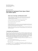
First, in Figure 4, we present the performance of a two-
relay CO-SFBC-OFDM scheme using G
2
code. The received
SNRs at all the relays are set to 35 dB. Two-ray, equal-power
Rayleigh fading channel model is used for all the links.
Number of subcarriers used is M
= 64 and modulation used
is 16-QAM. The CFO values at the destination for relays
1and2,[
1
,
2
], are taken to be [0.1, −0.08]. We plot the
BER performance of CO-SFBC-OFDM without IC and with
2 and 3 stages (m
= 2, 3) of IC. The BER performance of
noncooperative OFDM (i.e., simple point-to-point OFDM)
which has the same power per transmitted bit as that of CO-
SFBC-OFDM is also plotted for comparison. For CO-SFBC-
OFDM, we also plot the performance of an ideal case when
there is no interference, that is, when CFO
= [0, 0] and L = 1
(frequency-flat fading). From Figure 4, it can be seen that
without interference cancellation, the performance of CO-
SFBC-OFDM is worse than that of noncooperative OFDM.
The performance improves significantly with 2 and 3 stages
of cancellation, and it approaches the ideal performance of
cooperation without interference. For example, at a BER of
10
−2
, the performance improves by 12 dB with 3 stages of
cancellation compared to no cancellation, and it is 0.5 dB
close to the ideal performance. It can be seen that, at low
SNRs, the ideal performance with cooperation is worse than
that of no cooperation. This is because of the half-power split
of CO-SFBC-OFDM between broadcast and relay phases. It
can be observed that the slope of the BER curve of the ideal
performance is steeper (2nd order diversity) than that of no
cooperation (1st order diversity), and the crossover due to
this diversity order difference happens at around 24 dB.
Next, in Figure 5, we repeat the same experiment (as in
Figure 4) with 3 relays using G
3
code, which is obtained by
deleting one column from G
4
code in (38–40). The CFO
values at the destination for relays 1, 2, and 3, [
1
,
2
,
3
],
are taken to be [0.1,
−0.08, 0.06]. Similar observations on
the performance as in Figure 4 canbemadeinFigure 5 also.
D. Sreedhar and A. Chockalingam 9
10
−5
10
−4
10
−3
10
−2
10
−1
10
0
Bit error rate
0 5 10 15 20 25 30 35 40
Transmit power (dB)
2 relays, 64 subcarriers, CFO = [0.1, −0.08],
2-ray channel, SNR on broadcast links
= 35 dB,
16 QAM, AF protocol with phase comp
L = 2, nonzero CFO, no IC
L
= 2, nonzero CFO, IC, m = 2
L
= 2, nonzero CFO, IC, m = 3
L
= 1, CFO = 0, (ideal)
Non-cooperative OFDM
Figure 4: BER performance as a function of SNR for CO-SFBC-
OFDM on frequency-selective fading (L
= 2). M = 64, 2 relays
(N
= 2, G
2
code), CFO = [0.1, −0.08], 16-QAM, SNR on broadcast
links
= 35 dB. AF protocol and phase compensation at the relays.
For example, at a BER of 10
−2
, the performance of CO-
SFBC-OFDM improves by over 5 dB because of interference
cancellation compared to no cancellation. The difference is
less compared to G
2
code because of higher-order diversity
(3rd order diversity) in this case of G
3
code.
In Figure 6, we present the effectofnumberofrelayson
the performance of the interference cancellation algorithm.
Codes G
2
, G
3
, G
4
,andG
8
are used to evaluate the perfor-
mancewith2,3,4and8relays,respectively.Thereceived
SNRs at the relays are set to 45 dB. The CFOs for the different
relays are [0.1,
−0.08, 0.06, 0.12, −0.04, 0.02, 0.01, −0.07]
and all the channels are assumed to be 2-ray, equal-power
Rayleigh channels. The transmit power is kept at 18 dB per
bit. The BER performance of noncooperative OFDM and no
interference (L
= 1, CFO = 0, ideal) are also plotted. It can
be observed that without IC, the performance of CO-SFBC-
OFDM is worse than no cooperation and the performance
improves with increasing stages of IC and approaches the
ideal performance for all the cases considered. It can also
be observed that performance improves with increase in
number of relays, and the returns are diminishing with
increase in number of relays.
Simulation results for DF protocol
In Figures 7, 8,and9, we repeat the same experiments as
in Figures 4, 5,and6,respectively,forDFprotocolatthe
relays. For G
2
code, from Figure 7, it can be observed that
the performance without IC is worse than no cooperation.
The performance improves with increasing number of
10
−5
10
−4
10
−3
10
−2
10
−1
10
0
Bit error rate
0 5 10 15 20 25 30
Transmit power (dB)
3 relays, 64 subcarriers, CFO = [0.1, −0.08,0.06],
2-ray channel, SNR on broadcast links
= 35 dB,
16 QAM, AF protocol with phase comp
L = 2, nonzero CFO, no IC
L
= 2, nonzero CFO, IC, m = 2
L
= 2, nonzero CFO, IC, m = 3
L
= 1, CFO = 0, (ideal)
Non-cooperative OFDM
Figure 5: BER performance as a function of SNR for CO-SFBC-
OFDM on frequency-selective fading (L
= 2). M = 64, 3 relays
(N
= 3, G
3
code), CFO = [0.1, −0.08, 0.06], 16-QAM, SNR on
broadcast links
= 35 dB. AF protocol and phase compensation at
the relays.
10
−4
10
−3
10
−2
10
−1
Bit error rate
2345678
Number of relays, N
64 subcarriers, CFO = [0.1,−0.08, 0.06,0.12, −0.04,0.02, 0.01,−0.07],
2-ray channel, SNR on broadcast link
= 45 dB,
16-QAM, AF protocol with phase comp
Tr a ns mi t p ower
= 18 dB
L = 2, nonzero CFO, no IC
L
= 2, nonzero CFO, IC, m = 2
L
= 2, nonzero CFO, IC, m = 3
L
= 1, CFO = 0, (ideal)
Non-cooperative OFDM
Figure 6: BER performance as a function of number of relays for
CO-SFBC-OFDM on frequency-selective fading (L
= 2). M = 64,
Transmit power
= 18 dB per bit. CFO = [0.1, −0.08, 0.06, 0.12,
−0.04, 0.02, 0.01, −0.07], 16-QAM, SNR on broadcast links = 45 dB.
G
2
, G
3
, G
4
and G
8
codes with rates 1, 3/4, 3/4 and 1/2 are used. AF
protocol and phase compensation at the relays.
10 EURASIP Journal on Advances in Signal Processing
10
−4
10
−3
10
−2
10
−1
10
0
Bit error rate
0 5 10 15 20 25 30
Transmit power (dB)
2 relays, 64 subcarriers, CFO = [0.1, −0.08],
2-ray channel, SNR on broadcast links
= 35 dB,
16 QAM, DF protocol
L = 2, nonzero CFO, no IC
L
= 2, nonzero CFO, IC, m = 2
L
= 2, nonzero CFO, IC, m = 3
L
= 1, CFO = 0, (ideal)
Non-cooperative OFDM
Figure 7: BER performance as a function of SNR for CO-SFBC-
OFDM on frequency-selective fading (L
= 2). M = 64, 2 relays
(N
= 2, G
2
code), CFO = [0.1, −0.08], 16-QAM, SNR in broadcast
links
= 35 dB. DF protocol at the relays.
cancellation stages. For example, at a BER of 10
−2
, there
is a 6 dB improvement with 3 stages of cancellation. It can
also be observed that crossover between CO-SFBC-OFDM
(ideal) and no cooperation happens at a transmit power of
12 dB. For G
3
code also, Figure 8 shows similar performance
improvement with IC. Figure 9 shows the performance plots
for different number of relays using G
2
, G
3
, G
4
,andG
8
codes. Finally, comparing the performances of AF and DF
protocols, that is, Figures 4 with 7, 5 with 8,and6 with 9,
it can be observed that DF protocol has better performance
compared to AF protocol for all the cases considered.
5. CONCLUSIONS
In this paper, we addressed the issue of interference (ISI and
ICI due to synchronization errors and frequency selectivity of
the channel) when SFBC codes are employed in cooperative
OFDM systems, and proposed a low-complexity interference
mitigation approach. We proposed an interference cancel-
lation algorithm for a CO-SFBC-OFDM system with AF
protocol and phase compensation at the relays. We also
proposed an interference cancellation algorithm for the same
system when DF protocol is used at the relays, instead of AF
protocol with phase compensation. Our simulation results
showed that, with the proposed algorithms, the performance
of the CO-SFBC-OFDM was better than OFDM without
cooperation even in the presence of carrier synchronization
errors. It is also shown that DF protocol performs better
than the AF protocol in these CO-SFBC-OFDM systems.
The proposed IC algorithms can be extended to handle the
10
−4
10
−3
10
−2
10
−1
10
0
Bit error rate
0 5 10 15 20 25 30
Transmit power (dB)
3 relays, 64 subcarriers, CFO = [0.1, −0.08,0.06],
2-ray channel, SNR on broadcast links
= 35 dB,
16 QAM, DF protocol
L = 2, nonzero CFO, no IC
L
= 2, nonzero CFO, IC, m = 2
L
= 2, nonzero CFO, IC, m = 3
L
= 1, CFO = 0, (ideal)
Non-cooperative OFDM
Figure 8: BER performance as a function of SNR for CO-SFBC-
OFDM on frequency-selective fading (L
= 2). M = 64, 3 relays
(N
= 3, G
3
code), CFO = [0.1, −0.08, 0.06], 16-QAM, SNR in
broadcast links
= 35 dB. DF protocol at the relays.
10
−5
10
−4
10
−3
10
−2
10
−1
Bit error rate
2345678
Number of relays, N
64 subcarriers, CFO = [0.10,−0.08, 0.06,0.12, −0.04,0.02, 0.01,−0.07],
2-ray channel, SNR on broadcast link
= 45 dB, 16-QAM, DF protocol
Tr a ns mi t p ower
= 18 dB
L = 2, nonzero CFO, no IC
L
= 2, nonzero CFO, IC, m = 2
L
= 2, nonzero CFO, IC, m = 3
L
= 1, CFO = 0, (ideal)
Non-cooperative OFDM
Figure 9: BER performance as a function of number of relays for
CO-SFBC-OFDM on frequency-selective fading (L
= 2). M = 64,
at a transmit power of 18 dB per bit. CFO
= [0.1, −0.08, 0.06, 0.12,
−0.04, 0.02, 0.01, −0.07], 16-QAM, SNR in broadcast links = 45 dB.
G
2
, G
3
, G
4
and G
8
codes with rates 1, 3/4, 3/4 and 1/2 are used. DF
protocol is employed at the relays.
D. Sreedhar and A. Chockalingam 11
ISI effects caused due to imperfect timing on the relays-
to-destination channels, that is, due to nonzero timing
offsets at the destination. In the simulation results presented,
the receiver is assumed to know the exact channel state
information. The performance is expected to deteriorate
when the receiver has only an estimated channel state
information. The analysis of this deterioration and possible
ways of mitigating this would be an interesting area of future
work. Also, it is assumed that the relays are always available
for cooperation. Algorithms to “discover” the nodes that
could participate in the cooperation could also be an area of
future work.
ACKNOWLEDGMENTS
This work in part was presented in the IEEE PIMRC’2007,
Athens, September 2007. This work was supported in part
by the Swarnajayanti Fellowship, Department of Science
and Technology, New Delhi, Government of India, under
Project Ref: No.6/3/2002-S.F, and the DRDO-IISc Program
on Advanced Research in Mathematical Engineering.
REFERENCES
[1] A. Nosratinia, T. E. Hunter, and A. Hedayat, “Cooperative
communication in wireless networks,” IEEE Communications
Magazine, vol. 42, no. 10, pp. 74–80, 2004.
[2] A. Sendonaris, E. Erkip, and B. Aazhang, “User cooperation
diversity—part I: system description,” IEEE Transactions on
Communications, vol. 51, no. 11, pp. 1927–1938, 2003.
[3] J.N.Laneman,D.N.C.Tse,andG.W.Wornell,“Cooperative
diversity in wireless networks: efficient protocols and outage
behavior,” IEEE Transactions on Information Theory, vol. 50,
no. 12, pp. 3062–3080, 2004.
[4] T. E. Hunter and A. Nosratinia, “Diversity through coded
cooperation,” IEEE Transactions on Wireless Communications,
vol. 5, no. 2, pp. 283–289, 2006.
[5] J. N. Laneman and G. W. Wornell, “Distributed space-time
coded protocols for exploiting cooperative diversity in wireless
networks,” IEEE Transactions on Information Theory, vol. 49,
no. 10, pp. 2415–2426, 2003.
[6] S. Yiu, R. Schober, and L. Lampe, “Distributed space-time
block coding,” IEEE Transactions on Communications, vol. 54,
no. 7, pp. 1195–1206, 2006.
[7] L. Yu and A. Stefanov, “Cooperative space-time coding for
MIMO OFDM systems,” in Proceedings of the IEEE Military
Communications Conference (MILCOM ’05), vol. 2, pp. 990–
995, Atlatnic City, NJ, USA, October 2005.
[8] O S. Shin, A. M. Chan, H. T. Kung, and V. Tarokh, “Design
of an OFDM cooperative space-time diversity system,” IEEE
Transactions on Vehicular Technology,vol.56,no.4,part2,pp.
2203–2215, 2007.
[9] F. Ng and X. Li, “Cooperative STBC-OFDM transmissions
with imperfect synchronization in time and frequency,” in
Proceedings of the 39th Asilomar Conference on Signals, Systems
and Computers, pp. 524–528, Pacific Grove, Calif, USA,
October-November 2005.
[10] Z. Li, D. Qu, and G. Zhu, “An equalization technique for dis-
tributed STBC-OFDM system with multiple carrier frequency
offsets,” in Proceedings of the IEEE Wireless Communications
and Networking Conference (WCNC ’06), vol. 2, pp. 839–843,
Las Vegas, Nev, USA, April 2006.
[11] Y. Mei, Y. Hua, A. Swami, and B. Daneshrad, “Combating
synchronization errors in cooperative relays,” in Proceedings
of the IEEE Internat ional Conference on Acoustics, Speech
and Signal Processing (ICASSP ’05), vol. 3, pp. 369–372,
Philadelphia, Pa, USA, March 2005.
[12] E. G. Larsson and P. Stoica, Space-Time Block Coding for Wire-
less Communications, Cambridge University Press, Cambridge,
UK, 2003.
[13] D. Huang and K. B. Letaief, “An interference-cancellation
scheme for carrier frequency offsets correction in OFDMA
systems,” IEEE Transactions on Communications,vol.53,no.7,
pp. 1155–1165, 2005.
[14] S. Manohar, D. Sreedhar, V. Tikiya, and A. Chockalingam,
“Cancellation of multiuser interference due to carrier fre-
quency offsets in uplink OFDMA,” IEEE Transactions on
Wireless Communications, vol. 6, no. 7, pp. 2560–2571, 2007.
[15] S. M. Alamouti, “A simple transmit diversity technique for
wireless communications,” IEEE Journal on Selected Areas in
Communications, vol. 16, no. 8, pp. 1451–1458, 1998.
[16] H. B
¨
olcskei and A. J. Paulraj, “Space-frequency coded broad-
band OFDM systems,” in Proceedings of the IEEE Wireless
Communications and Networking Conference (WCNC ’00),
vol. 1, pp. 1–6, Chicago, Ill, USA, September 2000.
[17] Z. Liu, Y. Xin, and G. B. Giannakis, “Space-time-frequency
coded OFDM over frequency-selective fading channels,” IEEE
Transactions on Signal Processing, vol. 50, no. 10, pp. 2465–
2476, 2002.
[18] Y. Gong and K. B. Letaief, “An efficient space-frequency coded
wideband OFDM system for wireless communications,” IEEE
Transactions on Communications, vol. 51, no. 12, pp. 2019–
2029, 2003.
[19] D. Sreedhar and A. Chockalingam, “Detection of SFBC-
OFDM signals in frequency- and time-selective MIMO chan-
nels,” in Proceedings of the IEEE Wireless Communications and
Networking Conference (WCNC ’07), pp. 852–857, Kowloon,
Hong Kong, March 2007.
[20] D. Sreedhar, A. Chockalingam, and B. S. Rajan, “Single-
symbol ML decodable distributed STBCs for partially-
coherent cooperative networks,” submitted to IEEE Transac-
tions on Information Theory.
[21] E. Malkam
¨
aki and H. Leib, “Evaluating the performance
of convolutional codes over block fading channels,” IEEE
Transactions on Information Theory, vol. 45, no. 5, pp. 1643–
1646, 1999.
[22] M. Chiani, A. Conti, and O. Andrisano, “Outage evaluation
for slow frequency-hopping mobile radio systems,” IEEE
Transactions on Communications, vol. 47, no. 12, pp. 1865–
1874, 1999.
[23] V. Tarokh, H. Jafarkhani, and A. R. Calderbank, “Space-time
block codes from orthogonal designs,” IEEE Transactions on
Information Theory, vol. 45, no. 5, pp. 1456–1467, 1999.