Báo cáo hóa học: " Research Article Steganography in 3D Geometries and Images by Adjacent Bin Mapping" ppt
Bạn đang xem bản rút gọn của tài liệu. Xem và tải ngay bản đầy đủ của tài liệu tại đây (1022.29 KB, 10 trang )
Hindawi Publishing Corporation
EURASIP Journal on Information Security
Volume 2009, Article ID 317165, 10 pages
doi:10.1155/2009/317165
Research Article
Steganography in 3D G eometries and Images by
Adjacent Bin Mapping
Hao-Tian Wu and Jean-Luc Dugelay (EURASIP Member)
Multimedia Communications Department, Eurecom, 2229, Route des Cr
ˆ
etes, 06904 Sophia Antipolis, France
Correspondence should be addressed to Hao-Tian Wu,
Received 31 July 2008; Revised 14 December 2008; Accepted 6 February 2009
Recommended by Andreas Westfeld
A steganographic method called adjacent bin mapping (ABM) is presented. Firstly, it is applied to 3D geometries by mapping
the coordinates within two adjacent bins for data embedding. When applied to digital images, it becomes a kind of LSB hiding,
namely the LSB
+
algorithm. In order to prevent the detection using a metric named histogram tail, the hiding is performed in a
pseudorandom order. Then we show that the steganalytic algorithms based on histogram characteristic function (HCF) can be
prevented by implementing the LSB
+
algorithm on subsets of pixels having the same neighbor values. The experimental results
show that important high-order statistics of the cover image are preserved in this way while little distortion is introduced to 3D
geometric models with an appropriate bin size.
Copyright © 2009 H T. Wu and J L. Dugelay. This is an open access article distributed under the Creative Commons Attribution
License, which permits unrestricted use, distribution, and reproduction in any medium, provided the original work is properly
cited.
1. Introduction
Steganography, the art of covert communication by hiding
the presence of a message typically in multimedia content,
has attracted the interests of researchers (e.g., [1–4]).
Although the early steganographic methods can impercepti-
bly embed data into a cover object, traces of data embedding
can be found within the characteristics of the stego objects.
In the last decade, the technique of steganalysis (e.g., [5]) has
been developed for the detection of hidden data. It has been
shown by the novel steganalytic algorithms and detection-
theoretic analysis that several hiding methods are detectable.
Therefore, how to prevent the hidden message from being
detected is a central topic of steganography research.
Most of the steganalytic algorithms (e.g., [6–21]) exploit
statistical characteristics of the stego objects to detect the
existence of hidden message. For instance, the χ
2
(chi-
squared) technique [6]andProvos’stegdetect[7]calculate
the number of pixels whose values differ only in the
least significant bit (LSB) to detect random LSB hiding.
Furthermore, the occurrence of a pair of spatially adjacent
pixels is counted for steganalysis of random LSB hiding in
the regular/singular (RS) scheme [8] and more theoretical
sample pair analysis (SPA) [9]. By modeling the hiding
process as additive noise, histogram characteristic function
(HCF) is introduced in [10] to detect LSB, spread spectrum,
and discrete cosine transform (DCT) hiding methods. Two
ways of applying HCF are further proposed in [11]todetect
the LSB matching steganography in gray-scale images. The
detection-theoretic analysis for steganalysis can be found
in [12, 13] for the block-based embedding in the Gaussian
random covers and by modeling the cover as a Markov chain,
respectively. Moreover, features such as image quality metrics
[14] and the high-order statistics [15–17] are used through
supervised learning to detect the arbitrary hiding scheme.
To avoid being detected by the steganalytic algorithms,
quite a few algorithms are designed to preserve the statistics
of the cover object. An early attempt is the F5 algorithm
[22], in which some characteristics in the histogram of DCT
coefficients are preserved to prevent χ
2
attack [6]. However,
it is broken by the detector designed by Fridrich et al.
[18] by estimating the cover histogram from the suspected
image for comparison. In Provos’ Outguess [23], part of
JPEG coefficients are used to repair the modified histogram
due to data embedding. But the changes at the block
boundaries can be used for detection because the embedding
is performed in the blockwise transform domain [19]. A
method attempting to preserve the histogram after LSB
2 EURASIP Journal on Information Security
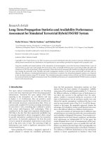
−4Δ −3Δ −2Δ −Δ 0 Δ 2Δ 3Δ 4Δ
···
···
2nΔ (2n +1)Δ 2(n +1)Δ
···
···
Unit −2 Unit −1 Unit 0 Unit 1 Unit n
01 01 01 01 01
R
Figure 1: Two adjacent bins form an embedding unit in the proposed adjacent bin mapping (ABM) method.
hiding is further presented by Franz [24], where a message
that mimics the imbalance between the adjacent histogram
bins is embedded. But the asymmetric embedding process
determined by a cooccurrence matrix can be exploited for
steganalytic attack, as shown in [20]. Similarly, Eggers et
al. propose a histogram-preserving data-mapping (HPDM)
method [25] by embedding a message with the same
distribution as the cover object. However, it is shown by
Tzschoppe et al. [26] that HPDM can be detected by Lyu and
Farid’s steganalytic method [15] because higher-frequency
components have not been separately treated from lower-
frequency ones. So a histogram restoration algorithm is
proposed in [27] without embedding in the low-probability
region, and further adopted to preserve some second-order
statistics in [28].
The model-based steganography [29]providesanew
perspective by generating a stego object with a given
distribution model. However, due to the lack of a per-
fect model, the steganographic algorithm using generalized
Cauchy distribution can be broken by using the first-
order statistics, that is, the measures without considering
the interdependencies between observations, such as mean
and variance [21]. In our preliminary work [30],anew
steganographic method is proposed to preserve the marginal
distribution of a cover inherently, which is called adjacent
bin mapping (ABM) hereinafter. In this paper, we apply
ABM method to three-dimensional (3D) geometric models
by mapping the coordinates within two adjacent bins for
data embedding. When applied to digital images, it becomes
a sort of LSB hiding, namely, the LSB
+
algorithm. For
image steganography, we analyze one case that the LSB
+
algorithm is detectable by defining a high-order metric
named histogram tail. And we try to prevent the detection
by performing the hiding in a pseudorandom order. To
prevent SPA steganalysis [9], the LSB
+
algorithm has been
implemented on subsets of pixels having the same four
neighbor values (left, right, up, and down), as shown in [30].
In this paper, we show that the steganalytic algorithms in [11]
to detect LSB matching steganography can be prevented by
performing the LSB
+
algorithm on subsets of pixels having
the same five neighbor values (i.e., left, right, up, down, and
up-right, denoted by 5-N in short). The experimental results
show that several important statistics of a cover image are
preserved in this way, while little distortion is introduced to
the virtual reality modeling language (VRML) models with
an appropriate bin size.
The rest of this paper is organized as follows. In the next
section, the ABM method is reviewed, and its application to
geometry steganography is proposed. In Section 3, the LSB
+
algorithm is presented, and we try to prevent the histogram
tail detection and the steganalytic algorithms based on HCF,
respectively. The experimental results are given in Section 4.
Finally, a conclusion is drawn in Section 5.
2. Adjacent Bin Mapping for Steganography
In this section, the data mapping method proposed in [30]
is reviewed, which is called adjacent bin mapping (ABM)
hereinafter. One important property of the ABM method
is that it preserves the marginal distribution of a cover
inherently. Other properties include the applicability to a
variety of cover objects (e.g., represented by integers, floating
or fixed point numbers) as well as the relative simplicity of
both encoding and decoding.
2.1. The Adjacent Bin Mapping Method. Different from other
embedding methods, the ABM method does not generate
new values in the stego object. Instead, the elements in two
adjacent bins are mapped to each other for data embedding.
In other words, we can say that the elements in the original
object are bijectively mapped to those in the stego object.
Suppose a cover object
C consists of N elements, that is, C =
{
e
1
, e
2
, ,e
N
},wheree
i
is an element with the index number
i
∈{1, 2, , N}.WeuseR to denote the distribution
range of the elements
{e
1
, e
2
, ,e
N
} and divide R into
nonoverlapping bins with the same size Δ. For the sake of
simplicity, we only discuss the one-dimensional case because
multiple dimensions can be processed one by one. As shown
in Figure 1, every two adjacent bins in the range of R form
an embedding unit, within which the bit values 0 and 1 are
assigned to the left and right bins, respectively. If the value of
an element e
i
falls into the left bin, it represents a bit value of
0, otherwise 1 if it is in the right bin. To embed a bit value of
0, an element should be kept in the left bin if it was originally
the case, or moved to the left bin if it originally was in the
right one. The process to embed a bit value of 1 is similar
as long as we replace “left” by “right” and vice versa. The
key idea of the ABM method is that the times of embedding
0 (1) should not exceed the amounts of elements originally
in the left (right) bins, respectively. During the embedding
process, we need to count the numbers of elements mapped
to both bins, respectively. Once the time of embedding 0 (or
1) has caught up with the amount of elements originally in
the left (or right) bin, no bit value can be further embedded
to ensure the bijective mapping between the elements in the
original object and those in the stego object.
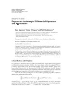
An illustration of the embedding process is shown
in Figure 2, where eleven elements
{e
1
, e
2
, ,e
11
} with
different values are in the Unit n. Suppose the elements are
processed in their index order to embed a string of bit values
“10011010010”. Since e
1
is in the left bin, it corresponds to
EURASIP Journal on Information Security 3
2nΔ (2n +1)Δ 2(n +1)Δ
e
2
e
5
e
9
e
1
e
8
e
7
e
3
e
11
e
6
e
4
e
10
Unit n
(a)
2nΔ (2n +1)Δ 2(n +1)Δ
e
2
e
9
e
8
e
3
e
6
e
5
e
1
e
7
e
11
e
4
e
10
Unit n
01
(b)
Figure 2: The eleven elements {e
1
, e
2
, , e
11
} in the embedding Unit n are used to embed a string of bit values “10011010010”. Only the first
nine bit values “100110100” can be embedded by mapping the eleven elements to generate the stego object on the right with the minimum
mean square error (MSE).
the bit value 0. Therefore, it should be moved to the right bin
to embed a bit value 1. For e
2
, it should remain in the left
bin to embed a bit value 0. To embed the third bit value 0
in the string, e
3
needs to be moved from the right to the left
bin. The rest of bit values are sequentially embedded until
the ninth one, which leads e
9
to remain in the left bin. Since
the number of elements mapped to the left bin of stego object
has reached 5, which is the amount of elements in the original
object, no bit value can be embedded in the Unit n any more.
Therefore, only the first nine bit values “100110100” can be
embedded by mapping the elements with the indices 2, 3, 6,
8, and 9 into the left bin and the remaining elements into
the right bin to generate the stego object. To minimize the
distortion of cover object in the mean square error (MSE)
criterion, the elements in the same bin should be ordered
according to their original values. In the optimal scheme,
e
2
, e
9
, e
8
, e
3
, e
6
will have the values of e
2
, e
5
, e
9
, e
1
, e
8
, while
the values of e
5
, e
1
, e
7
, e
11
, e
4
, e
10
are modified to those of
e
7
, e
3
, e
11
, e
6
, e
4
, e
10
to generate the stego object.
If all the elements originally in the same bin have the
identical values, there is no need to sort the elements mapped
to that bin. Otherwise, the mapping process minimizing the
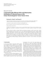
distortion depends on the order the elements are processed.
In Figure 3, the same elements as shown in Figure 2 are used
to embed the bit values “100110100” except that the indices
of the ninth and tenth ones are exchanged. To embed the
ninth bit value 0, the element e
9
should be moved from
the right bin to the left one, while it remains in the left
bin in Figure 2. To minimize the distortion in the MSE
criterion, the elements e
2
, e
8
, e
3
, e
6
, e
9
will have the values
of e
2
, e
5
, e
10
, e
1
, e
8
, while the values of e
5
, e
10
, e
1
, e
7
, e
11
, e
4
are
changed to those of e
7
, e
3
, e
11
, e
6
, e
4
, e
9
,respectively.
The decoding process is much simpler: given the same
scanning order as in the embedding process, the bit values
can be extracted from the element positions (i.e., in the left
or right bin) one by one. The extracted bit value will be 0 if an
element is located in the left bin, or 1 if it is in the right one.
For each embedding unit, once all elements in one bin (left or
right) have been used up, the extraction process is finished.
For example, the bit values that can be extracted from the
Unit n in Figures 2(b) and 3(b) are not “10011010011” but
“100110100”. Since the embedding and extraction operations
in one unit do not interfere with those performed in other
units, the operations in every embedding unit can be carried
out in parallel. So both encoding and decoding processes
can be performed according to the scrambled indices of all
elements with a secret key shared by the sender and receiver.
The hiding rate is maximized if the maximum number
of 0s or 1s are embedded. A parameter θ
∈ (0, 1] can be
used to adjust the hiding rate, that is, the embedding process
stops once the number of embedded bits reaches a fraction of
the amount originally in one bin (left or right). Accordingly,
the same value of θ should be used in the extraction process.
Suppose there are L and M elements in the two bins of an
embedding unit. Without loss of generality, we assume that
M is always inferior to L, then the minimum and maximum
amount of bits that can be embedded are M and L + M
− 1.
With the parameter θ, the low and upper bounds of capacity
in that unit will be
Mθ and (L + M − 1)θ bits, where
· represents the ceil function. So the hiding rate can be
adjusted with the parameter θ, which should be shared by
the sender and receiver.
2.2. Steganography in 3D Geometries Using the ABM Method.
In literature, a majority of steganography research has been
conducted on digital images for their popularity. With the
development of 3D scanning and modeling techniques,
more and more 3D models have been used for geometry
representation. With the dissemination such as using the
virtual reality modeling language (VRML) [31]torepresent
3D graphics on the Web, 3D models have become potential
covers for covert communication. In the following, the ABM
method is applied to 3D geometry with coordinates.
Suppose there are N vectors of position in a 3D geometry
represented by
P ={p
1
, ,p
N
}, where a vector p
i
specifies
the coordinates
{p
ix
, p
iy
, p
iz
} in R
3
for i = 1, 2, , N.
The proposed mapping method can be applied to three
coordinates sets
{p
1x
, p
2x
, , p
Nx
}, {p
1y
, p
2y
, , p
Ny
},and
{p
1z
, p
2z
, , p
Nz
} on the X, Y,andZ axes with the same bin
size Δ, respectively. Firstly, the histogram of coordinates on
each axis, that is, the number of coordinates in every bin,
needs to be calculated. For the cover object represented by
floating point number, the computation of histograms can
be subject to the smallest value within it. For instance, by
denoting the smallest value among the coordinates on the
X axis as p
xm
, we calculate the value of p
xb
=p
xm
/Δ×
Δ.Foreachvaluep
ix
in a 3D geometry, we know it is
located in the (
(p
ix
− p
xb
)/Δ + 1)th bin from the starting
4 EURASIP Journal on Information Security
2nΔ (2n +1)Δ 2(n +1)Δ
e
2
e
5
e
10
e
1
e
8
e
7
e
3
e
11
e
6
e
4
e
9
Unit n
(a)
2nΔ (2n +1)Δ 2(n +1)Δ
e
2
e
8
e
3
e
6
e
9
e
5
e
10
e
1
e
7
e
11
e
4
Unit n
01
(b)
Figure 3: The same elements as shown in Figure 2 are used to embed a string of bit values “100110100” except that the indices of the ninth
and tenth elements are exchanged. As a result, the optimal mapping scheme to minimize the distortion (in MSE criterion) is different from
that in Figure 2.
point p
xb
. Since the embedding process does not generate
new values, the value of p
xb
can also be obtained from the
smallest coordinate in the stego geometry with the value of
Δ. Therefore, the histograms of stego geometry, which are
the same as the original ones, can be calculated to extract
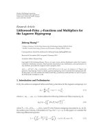
the embedded data. Figure 4 shows the original and stego
geometries “gears” using the ABM method. The distortion
of stego geometry is measured with the 3D signal-to-noise
ratio (SNR) defined in [32]. By setting the value of Δ at
0.005 and the parameter θ
= 1, the 3D SNR of the stego
geometry “gears” is 63.8260 (dB). As the embedding process
does not generate new values, the marginal distribution of
cover geometry is preserved.
3. Image Steganography with
the LSB
+
Algorithm
To apply the ABM method to digital images, in which the
pixel values are represented by integers, the bin size Δ is set
at 1 to minimize the distortion. As shown in Figure 5,every
two adjacent pixel values within [0, 255] are used to form an
embedding unit, respectively. The bit value corresponding
to each bin has not been labeled because it can be directly
extracted from the LSB of pixel value. Since the mapping
is always performed in the same unit, only the LSB of pixel
value is changeable. So the ABM method becomes a kind of
LSB hiding, namely, the LSB
+
algorithm.
3.1. The LSB
+
Algorithm. Given a gray-scale image, its
histogram is calculated by counting the pixels with the same
value, that is, the amount of pixels within every bin. Since
the operations in one embedding unit are independent from
those in the other units, we only discuss the operations in an
arbitrary unit. In the normal LSB hiding, a string of bit values
are used to replace the LSBs of pixel values. The histogram of
cover image is probably changed due to the randomness of
embedded data. Obviously, the histogram will be preserved
if the amount of pixels within each bin is unchanged. So we
constrain the replacement operations in the LSB
+
algorithm.
As discussed previously in the general method, the key idea
is that the number of embedded 0s and 1s should not exceed
the original ones in the LSBs. Suppose that there are L and M
pixels originally in the left and right bins of a unit, the time
of embedding 0 should be no more than L, and the time of
embedding 1 should not exceed M, respectively. Once there
are L 0s (or M 1s) having been embedded, all the rest LSBs
should be replaced with 1s (or 0s). In this way, the amounts
of 0s and 1s in the LSBs are unchanged by data embedding.
In the decoding process, the embedded bits are extracted one
by one in the same order as in the embedding process. The
extraction process is finished as soon as all LSBs in one bin
(either left or right) have been extracted. Since part of the
LSBs are used to repair the cover histogram, a portion of
capacity is sacrificed.
3.2. The Histog ram Tail Detection. For an embedding unit
of pixel values, we define the metric of histogram tail as
the number of pixels that has not been scanned in one bin
until all pixels in the other bin have been. Given the Unit
n as shown in Figure 6, there are two pixels in the left bin
after the M pixels in the right bin have been scanned in a
certain order. Then the histogram tail for Unit n is 2 in that
scanning order. Obviously, the definition of histogram tail
depends on the order in which the pixels are scanned. If we
intentionally scan the pixels with value 2n
−1 before all those
with value 2(n
−1), the histogram tail will be L. By employing
the same scanning order as in the embedding process, the
histogram tail is actually the number of pixels used to repair
the histogram. Take the Unit n in Figure 6, for instance, after
M 1s have been embedded by mapping M pixels to the right
bin of stego object, the last 2 pixels must be mapped to the
left bin to preserve the histogram.
The LSB
+
hiding significantly affects the histogram tail of
cover image. If the hiding is performed in the raster order,
that is, by rows from top to bottom and within each row
from left to right, the histogram tail of the 128 units (from
[0, 1] to [254, 255]) is greatly increased by implementing the
LSB
+
algorithm with θ = 1, as shown in Figure 7. This
phenomenon is caused because the two bins in the same unit
contain different numbers of pixels, while a secret message
consists of almost the same number of 0s and 1s. Due to
the interdependencies between the neighboring pixels, the
pixels within the same unit are closely distributed in a natural
image. That means we can probably find a pixel nearby
another one with the same binary value except in the LSB.
Therefore, the histogram tail of an original image in the
raster order is generally small. When the LSB
+
hiding is
EURASIP Journal on Information Security 5
(a) The original 3D VRML model “gears” (b) The stego model “gears” with 3D SNR =
63.8260 dB
Figure 4: The 3D VRML model “gears” and its stego model generated by the ABM method with the bin size Δ = 0.005 and the parameter
θ
= 1.
···
···
Unit 1 Unit 2 Unit 3 Unit 128
0 1 2 3 4 5 254 255
Figure 5: Every two adjacent pixel values within [0, 255] are used to
form an embedding unit for digital gray-scale images, respectively.
··· ···
Unit n
L
M
2(n
− 1) 2n − 1
Figure 6: An illustration of the definition of histogram tail.
performed in the raster order to embed a secret message with
the equal number of 0s and 1s, the bin with less pixels will
normally be firstly filled so that the rest pixels are all in the
other bin. Therefore, the histogram tail of stego image in the
same order is significantly increased.
To avoid the histogram tail detection, one way is to
perform the LSB
+
hiding in a pseudorandom order by
permuting the pixel indices with a secret key. Without
the key, a steganalyst does not know the correct order
employed in the embedding process. As we have discussed,
the histogram tail for each unit depends on the order in
which the pixels are processed. It will be suspicious to have a
large histogram tail in the raster order but a large histogram
tail in a special order does not carry much information as
it happens in a natural image. After we perform the LSB
+
hiding with θ = 1 in a random order, the histogram tail of
stego image in the raster order is close to that of original
image, as shown in Figure 8.
3.3. Preventing the Steganalytic Algorithms Bas ed on HCF.
The histogram characteristic function (HCF), defined as the
discrete Fourier transform (DFT) of image histogram, is first
used by Harmsen and Pearlman [10] for the detection of
additive noise steganography. Based on HCF, the center of
mass (COM) is calculated by
C
H[k]
=
k∈K
k
H[k]
i∈K
H[i]
,(1)
where H[k] is the HCF, K
={1, 2, ,N/2−1},andN is the
DFT length. For gray-scale images, N
= 256. Since the LSB
+
algorithm does not change the cover histogram, the HCF
and COM of cover image are both preserved. Therefore, the
steganalytic algorithms that are simply based on the COM of
HCF (HCF-COM) are prevented.
In [11], two ways of applying the HCF are further
proposed to detect the LSB matching steganography in
the gray-scale images. The first algorithm downsamples a
suspected image by a factor of two in both dimensions using
an averaging filter. Then the downsampled image is used to
calibrate the HCF-COM of the full-sized image. It is observed
that for the presence of LSB matching steganography, the
HCF-COM of the full-sized image is more affected than the
one of the downsampled image. As for an image without the
hidden data, HCF-COMs of the downsampled and full-sized
images are roughly the same. In the second algorithm, the
two-dimensional adjacency histogram is used instead of the
standard one for steganalysis by considering one horizontal
neighboring pixel. Since the adjacent pixels tend to have close
intensities, the adjacency histogram is sparse off the diagonal.
Although the cover histogram is unchanged by the LSB
+
algorithm, the histogram of the downsampled image is
not preserved for it is a high-order metric. As we can see
from Figure 9, noticeable change has been made to the
histogram of the downsampled image after performing the
LSB
+
algorithm on the image “Oregon” with θ = 1. So
the LSB
+
algorithm would probably be detected by the
steganalytic algorithms in [11]ifappliedonallpixelsofa
cover image. To improve the security, we need to preserve
6 EURASIP Journal on Information Security
9
8
7
6
5
4
3
2
1
0 20 40 60 80 100 120 140
(a) Histogram tail of the original image in the raster order
900
800
700
600
500
400
300
200
100
0
0 20 40 60 80 100 120 140
(b) Histogram tail after implementing the LSB
+
algorithm on the
whole image with θ
= 1 in the raster order
Figure 7: The histogram tail of the cover image “Oregon” in the raster order is significantly increased by the LSB
+
hiding.
8
7
6
5
4
3
2
1
0 20 40 60 80 100 120 140
Figure 8: Histogram tail of the stego image “Oregon” in the raster
order by performing the LSB
+
hiding in a pseudorandom order with
θ
= 1.
the histogram of the downsampled image first. If we perform
the LSB
+
hiding on the subsets of pixels with the same right,
up, and up-right neighbor values (see in Figure 10 for the
selection of those pixels), only one out of the four pixels in
a downsampling unit may be changed for data embedding
or compensation. As the histogram of pixels in the same
subset is preserved by the LSB
+
algorithm, the histogram of
downsampled values is also unchanged.
To preserve the adjacency histogram as suggested in [11],
the left and right neighbor values of every pixel in a selected
subset should be the same. If the two-dimensional adjacency
histogram is calculated vertically, the pixel values up and
down the current one should also be the same. So we perform
the LSB
+
hiding on the subsets of pixels having the same five
neighbor values (left, right, up, down, and up-right, denoted
by 5-N in short) as shown in Figure 10, where the pixels
marked in black are chosen as the neighbors of others, that
150
100
50
0
−50
−100
−150
0 50 100 150 200 250 300
Figure 9: The difference between the histograms of the downsam-
pled images (size: 256
× 256) before and after performing the LSB
+
hiding on the whole image “Oregon” (size: 512 × 512) with θ = 1.
is, only the light-colored pixels are grouped into a subset if
they have the same five neighbor values. As for the light-
colored pixels in the leftmost column and in the bottom row,
only four neighbor values are considered so that they are
separately treated, respectively.
By implementing the LSB
+
algorithm in the 5-N way,
the histograms of cover image and its downsampled version,
the adjacency histogram of cover image, are all preserved.
As a result, HCF-COMs of the full-sized and downsampled
images, the two-dimensional COM based on the adjacency
histogram, are unchanged by the hidden data. So the
steganalytic algorithms in [11] to detect the LSB matching
steganography and the SPA steganalysis in [9] to detect the
random LSB hiding are prevented in principle. Moreover,
all the steganalytic algorithms using the first-order statistics
of cover image are not efficient because the marginal
distribution is inherently preserved by the LSB
+
algorithm.
EURASIP Journal on Information Security 7
Figure 10: The pixels in black are chosen as the neighbors of others
so that only the light-colored pixels with the same five neighbor
values (left, right, up, down, and up-right) are grouped into a
subset. As for the light-colored pixels in the leftmost column, only
the right, up, down, and up-right neighbor values are considered,
while the left, right, up, and up-right neighbor values are taken into
account for the light-colored pixels in the bottom row.
Table 1: The VRML models used in the experiments.
VRML
models
Number of
vertices
The bin
size Δ
3D SNR
(dB)
Hiding rate
(bit/coordinate)
lamp 676 0.002 62.3696 0.2041
pear 891 0.0001 61.0243 0.2132
sgilogo 1224 0.001 60.4583 0.1062
pavilion 7334 0.04 60.7356 0.3664
indigo 8389 0.0002 66.1693 0.3789
gears 24546 0.005 63.8260 0.5066
4. Experimental Results
4.1. Steganography in 3D Geomet ries. The proposed ABM
method was implemented on the 3D VRML models listed
in Tabl e 1 (downloaded from />ukvrsig/vrml.html), in which the coordinates are represented
by floating point numbers. The 3D signal-to-noise ratio (3D
SNR) as defined in [32] is used to represent the distortion
of stego geometry. As the modification of each coordinate
in the cover geometry is bounded by
±2Δ, we required that
the 3D SNR of stego geometry to be greater than 60 (dB) by
adjusting the bin size Δ, as shown in Ta bl e 1.
Atrade-off between the distortion and the data hiding
rate exists for 3D geometry. As shown in Figure 11, the data
hiding rate is low when the bin size is tiny because there are
few coordinates in the same bin. When there is no coordinate
in one bin, no data can be embedded despite how many
coordinates in the other bin of the same embedding unit are
present. If the value of Δ is increased within a certain range,
the coordinates are more equally distributed in each bin of
an embedding unit so that the data hiding rate is increased.
Meanwhile, more geometrical distortion is caused when the
bin size is increased. If the bin size is adaptively chosen to
make the distortion unnoticeable, it should be sent to the
receiver for decoding.
Table 2: Several images used in the experiments.
Images
Size
PSNR (dB) Capacity PSNR Capacity
(5-N) (5-N) (4-N) (4-N)
Casimir
512
× 512 73.7550 840 68.3892 2775
Church
512
× 512 65.2218 6684 63.9139 9311
Fall
512
× 512 93.2853 11 87.2647 38
Louvre
512
× 512 77.0528 426 71.8944 1293
Oregon
512
× 512 67.7132 3586 65.5201 6225
Stockholm
512
× 512 68.9596 2818 68.0772 3608
With the ABM method, steganography in the cover
object represented by floating point numbers is enabled,
such as 3D geometrical models with coordinates. Since
the previous steganalysis archives are mainly dedicated to
images, techniques to detect the hidden data in the other
multimedia content are still rare. A secret key shared by the
sender and receiver can be used to scramble the element
indices to perform the hiding in a pseudorandom order.
Since the bin size can be adaptively chosen for the cover
object represented by the floating point numbers, it can also
be used as a secret key to decode the hidden message from
the stego object.
4.2. Steganography in Images. The LSB
+
algorithm was
implemented with θ
= 1 on 1000 gray images provided by
BOWS-2 [33] in the 5-N way, that is, on every subset of pixels
having the same five neighbor values (left, right, up, down,
and up-right). It should be noted that the original unmarked
images from BOWS2 have been JPEG compressed, scaled,
and cropped to the final format and were recommended to be
used for experimental evaluation in this special issue. Tab le 2
lists a few images used in the experiments and the number
of bits that can be embedded, respectively. The peak signal-
to-noise ratio (PSNR) of the stego images was calculated by
setting the maximum pixel value to 255.
As shown in Ta bl e 2, the PSNRs of the stego images are
all above 60 (dB) when the LSB
+
algorithm is implemented
in the 5-N way with θ
= 1. Not surprisingly, the PSNR is
higher when less bits are hidden in a stego image. From the
experimental results, it can be seen that the capacity varies
from one image to another. For a cover image consisting
of many pixels having the same neighbor values, the hiding
rate is high. Otherwise, for a cover image such as “Fall”
in which this is hardly the case, only a few bits can be
embedded. As shown in Figure 10, only one out of four pixel
values is possible to be modified if the LSB
+
algorithm is
implemented in the 5-N way. In our experiments, the hiding
rate is normally no more than 0.06 bit/pixel. Compared with
applying the LSB
+
algorithm in the 4-N way (left, right, up,
and down) [30], the capacity in the 5-N way is lower because
the requirement on the neighbor values of pixels within a
selected subset is stricter, as shown in Ta bl e 2.
The experimental results show that the histogram of
downsampled image is well preserved, that is, there is no
difference between the histograms of two images down-
sampled from the original and stego ones, respectively. We
8 EURASIP Journal on Information Security
0.8
0.7
0.6
0.5
0.4
0.3
0.2
0.1
The data hiding rate (bit/coordinate)
00.005 0.01 0.015 0.02
The bin size Δ
(a) The hiding rate by applying the ABM method
85
80
75
70
65
60
55
50
The 3D SNR (dB)
00.005 0.01 0.015 0.02
The bin size Δ
(b) The 3D SNR of the stego geometry
Figure 11: The 3D SNR of the stego geometry “gears” and the hiding rate change with respect to the bin size Δ.
35
30
25
20
15
10
5
0
0 5 10 15 20 25 30 35
Figure 12: HCF-COMs of the stego images generated by applying
the LSB
+
algorithminthe5-Nway:(X-axis) C(H
s
[k]) and (Y-axis)
C(H
s
[k]) for the first 1000 gray images provided by BOWS-2.
use C(H
c
[k]) and C(H
c
[k]) to denote the HCF-COMs of
original image and its downsampled version, while C(H
s
[k])
and C(H
s
[k]) are used to denote the HCF-COMs of stego
image and its downsampled version. The HCF-COMs of
1000 stego images and their downsampled versions are
shown in Figure 12, which are exactly the same as those of
original images.
As pointed out in [11], the value of C (H
c
[k]) is close to
that of C(H
c
[k]). By performing the LSB
+
hiding in the 5-
N way, the values of C (H
s
[k]) and C(H
s
[k]) are identical
to those of C(H
c
[k]) and C(H
c
[k]) so that C(H
s
[k]) ≈
C(H
s
[k]). As shown in Figure 13 for the first 1000 gray
images in BOWS-2, the difference between HCF-COM of
the downsampled and full-sized images, that is, C(H
c
[k]) −
C(H
c
[k]), is the same for the original image and the stego
image generated by the LSB
+
algorithm in the 5-N way.
Therefore, the difference between the two HCF-COMs (i.e.,
6
4
2
0
−2
−4
−6
−6 −4 −20 2 4 6
Figure 13: (X-axis) C(H
c
[k]) − C(H
c
[k]) of the original image
isthesameas(Y-axis) C(H
s
[k]) − C(H
s
[k]) of the stego image
generated in the 5-N way for the first 1000 gray images in BOWS-2.
of the full-sized and downsampled images) cannot be used to
distinguish the stego images from the clean ones in the case
that the LSB
+
algorithm is applied in the 5-N way. It should
be noted that this conclusion does not depend on the data
used here, and the same results can be obtained from other
image sets.
Meanwhile, the adjacency histogram was also preserved
by applying the LSB
+
algorithm in the 5-N way, so that the
steganalytic algorithms in [11] and the SPA steganalysis in
[9] are both prevented. Furthermore, histogram tail of the
cover image in the raster order was rarely changed. For the
six images listed in Tab le 2, the experimental results show
that the histogram tail in the raster order was unchanged by
the hidden message. However, it is not yet possible to claim
that the proposed algorithm is practically secure before other
EURASIP Journal on Information Security 9
steganalysis algorithms using the high-order statistics would
have been tested. Recently, high-order statistical features have
been used by supervised learning for steganalysis; our future
work includes to investigate if the proposed algorithm can
resist those blind learning-based algorithms (e.g., [16]).
5. Conclusion
In this paper, we have presented the adjacent bin mapping
(ABM) method for steganography and applied it to 3D
geometrical models. By choosing an appropriate bin size,
little distortion has been introduced to the VRML models
to hide a secret message. Therefore, how to detect the
secret message hidden in 3D geometries should be further
investigated as well as in other covers represented by floating
point numbers.
When applied to the gray-scale images, the ABM method
becomes a kind of LSB hiding, namely, the LSB
+
algorithm.
The histogram tail has been defined to detect the LSB
+
hiding in the raster order, and we have avoided the detection
by performing the hiding in a pseudorandom order. To
prevent the steganalytic algorithms in [11] to detect the
LSB matching steganography, the pixels with the same five
neighbor values (i.e., left, right, up, down, and up-right)
have been grouped into each subset. It has been shown that
several high-order statistics are preserved by applying the
LSB
+
algorithm on the selected subsets of pixels. Our future
work is to investigate if the proposed algorithm also resists to
the blind learning-based steganalysis (e.g., [16]).
References
[1] R. J. Anderson and F. A. P. Petitcolas, “On the limits of
steganography,” IEEE Journal on Selected Areas in Communi-
cations, vol. 16, no. 4, pp. 474–481, 1998.
[2] F. A. P. Petitcolas, R. J. Anderson, and M. G. Kuhn, “Informa-
tion hiding—a survey,” Proceedings of the IEEE, vol. 87, no. 7,
pp. 1062–1078, 1999.
[3] G. J. Simmons, “The prisoner’s problem and the subliminal
channel,” in Advances in Cryptology, vol. 196 of Lecture Notes
in Computer Science, pp. 51–67, Plenum Press, New York, NY,
USA, 19984.
[4] C. Cachin, “An information theoretic model for steganog-
raphy,” in Proceedings of the 2nd International Workshop on
Information Hiding (IH ’98), vol. 1525 of Lecture Notes in
Computer Science, pp. 306–318, Portland, Ore, USA, April
1998.
[5] N. F. Johnson and S. Jajodia, “Steganalysis of images created
using current steganography software,” in Proceedings of the
2nd International Workshop on Information Hiding (IH ’98),
vol. 1525 of Lecture Notes in Computer Science, pp. 273–289,
Portland, Ore, USA, April 1998.
[6] A. Westfeld and A. Pfitzmann, “Attacks on steganographic
systems,” in Proceedings of the 3rd International Workshop on
Information Hiding (IH ’99), vol. 1768 of Lecture Notes in
Computer Science, pp. 61–76, Dresden, Germany, September-
October 1999.
[7] N. Provos and P. Honeyman, “Detecting steganographic
content on the internet,” in Proceedings of the ISOC Network
and Distributed System Security Symposium (NDSS ’02),pp.
2–13, San Diego, Calif, USA, February 2002.
[8] J. Fridrich, M. Goljan, and R. Du, “Reliable detection of LSB
steganography in color and grayscale images,” in Proceedings
of the ACM Workshop on Multimedia and Security, pp. 27–30,
Ottawa, Canada, October 2001.
[9] S. Dumitrescu, X. Wu, and Z. Wang, “Detection of LSB
steganography via sample pair analysis,” IEEE Transactions on
Signal Processing, vol. 51, no. 7, pp. 1995–2007, 2003.
[10] J. J. Harmsen and W. A. Pearlman, “Steganalysis of additive
noise modelable information hiding,” in Security and Water-
marking of Multimedia Contents V, vol. 5020 of Proceedings of
SPIE, pp. 131–142, Santa Clara, Calif, USA, January 2003.
[11] A. D. Ker, “Steganalysis of LSB matching in grayscale images,”
IEEE Signal Processing Letters, vol. 12, no. 6, pp. 441–444, 2005.
[12] Y. Wang and P. Moulin, “Steganalysis of block-structured
stegotext,” in Security, Steganography, and Watermaking of
Multimedia Contents VI, vol. 5306 of Proceedings of SPIE,pp.
477–488, San Jose, Calif, USA, January 2004.
[13] K. Sullivan, U. Madhow, S. Chandrasekaran, and B. S. Man-
junath, “Steganalysis for Markov cover data with applications
to images,” IEEE Transactions on Information Forensics and
Securit y, vol. 1, no. 2, pp. 275–287, 2006.
[14] I. Avcibas¸, N. Memon, and B. Sankur, “Steganalysis using
image quality metrics,” IEEE Transactions on Image Processing,
vol. 12, no. 2, pp. 221–229, 2003.
[15] S. Lyu and H. Farid, “Steganalysis using color wavelet
statistics and one-class support vector machines,” in Security,
Steganography, and Watermaking of Multimedia Contents VI,
vol. 5306 of Proceedings of SPIE, pp. 35–45, San Jose, Calif,
USA, January 2004.
[16] S. Lyu and H. Farid, “Steganalysis using higher-order image
statistics,” IEEE Transactions on Information Forensics and
Securit y, vol. 1, no. 1, pp. 111–119, 2006.
[17] Y. Wang and P. Moulin, “Optimized feature extraction for
learning-based image steganalysis,” IEEE Transactions on Infor-
mation Forensics and Security, vol. 2, no. 1, pp. 31–45, 2007.
[18] J. Fridrich, M. Goljan, and D. Hogea, “Steganalysis of JPEG
images: breaking the F5 algorithm,” in Proceedings of the
5th International Workshop on Information Hiding (IH ’02),
vol. 2578 of Lecture Notes in Computer Science, pp. 310–323,
Noordwijkerhout, The Netherlands, October 2002.
[19] J. Fridrich, M. Goljan, and D. Hogea, “Attacking the outguess,”
in Proceedings of the ACM Workshop on Multimedia and
Securit y, pp. 967–982, Juan-Pins, France, December 2002.
[20] R. B
¨
ohme and A. Westfeld, “Exploiting preserved statistics for
steganalysis,” in Proceedings of the 6th International Workshop
on Information Hiding (IH ’04), vol. 3200 of Lecture Notes in
Computer Science, pp. 82–96, Toronto, Canada, May 2004.
[21] R. B
¨
ohme and A. Westfeld, “Breaking cauchy model-based
JPEG steganography with first order statistics,” in Proceedings
of 9th European Symposium on Research in Computer Security
(ESORICS ’04), P. Samarati, P. Y. A. Ryan, D. Gollmann, and
R. Molva, Eds., vol. 3193 of Lecture Notes in Computer Science,
pp. 125–140, Sophia Antipolis, France, September 2004.
[22] A. Westfeld, “F5—a steganographic algorithm: high capacity
despite better steganalysis,” in Proceedings of the 4th Interna-
tional Workshop on Information Hiding (IH ’01), vol. 2137 of
Lecture Notes in Computer Science, pp. 289–302, Pittsburgh, Pa,
USA, April 2001.
[23] N. Provos, “Defending against statistical steganalysis,” in
Proceedings of the 10th Conference on USENIX Security Sym-
posium, pp. 323–335, Washington DC, USA, August 2001.
[24] E. Franz, “Steganography preserving statistical properties,” in
Proceedings of the 5th International Workshop on Information
Hiding (IH ’02), vol. 2578 of Lecture Notes in Computer Science,
10 EURASIP Journal on Information Security
pp. 278–294, Noordwijkerhout, The Netherlands, October
2002.
[25] J. J. Eggers, R. B
¨
auml, and B. Girod, “A communications
approach to image steganography,” in Security and Water-
marking of Multimedia Contents IV, vol. 4675 of Proceedings
of SPIE, pp. 26–37, San Jose, Calif, USA, January 2002.
[26] R. Tzschoppe, R. B
¨
auml,J.B.Huber,andA.Kaup,“Stegano-
graphic system based on higher-order statistics,” in Security
and Watermarking of Multimedia Contents V, vol. 5020 of
Proceedings of SPIE, pp. 156–166, Santa Clara, Calif, USA,
January 2003.
[27] K. Solanki, K. Sullivan, U. Madhow, B. S. Manjunath, and S.
Chandrasekaran, “Provably secure steganography: achieving
zero K-L divergence using statistical restoration,” in Proceed-
ings of IEEE International Conference on Image Processing (ICIP
’06), pp. 125–128, Atlanta, Ga, USA, Octobor 2006.
[28] A. Sarkar, K. Solanki, U. Madhow, S. Chandrasekaran, and B.
S. Manjunath, “Secure steganography: statistical restoration
of the second order dependencies for improved security,”
in Proceedings of the 32nd IEEE International Conference on
Acoustics, Speech and Signal Processing (ICASSP ’07), vol. 2, pp.
277–280, Honolulu, Hawaii, USA, April 2007.
[29] P. Sallee, “Model-based steganography,” in Proceedings of the
2nd International Workshop on Digital Watermarking (IWDW
’03), vol. 2939 of Lecture Notes in Computer Science, pp. 154–
167, Seoul, Korea, October 2003.
[30] H T. Wu, J L. Dugelay, and Y M. Cheung, “A data mapping
method for steganography and its application to images,” in
Proceedings of the 10th International Workshop on Information
Hiding (IH ’08), vol. 5284 of Lecture Notes in Computer Science,
pp. 236–250, Santa Barbara, Calif, USA, May 2008.
[31] ISO/IEC DIS 14772-1, “The virtual reality modeling lan-
guage,” />[32] H T. Wu and J L. Dugelay, “Reversible watermarking of 3D
mesh models by prediction-error expansion,” in Proceedings
of the 10th IEEE International Workshop on Multimedia
Signal Processing (MMSP ’08), pp. 797–802, Cairns, Australia,
October 2008.
[33] “Break our watermarking system 2nd Ed,” http://bows2
.gipsa-lab.inpg.fr.