Báo cáo hóa học: "Research Article Intelligent Stale-Frame Discards for Real-Time Video Streaming over Wireless Ad Hoc Networks" ppt
Bạn đang xem bản rút gọn của tài liệu. Xem và tải ngay bản đầy đủ của tài liệu tại đây (1.2 MB, 10 trang )
Hindawi Publishing Corporation
EURASIP Journal on Wireless Communications and Networking
Volume 2009, Article ID 486165, 10 pages
doi:10.1155/2009/486165
Research Article
Intelligent Stale-Frame Discards for Real-Time Video Streaming
over Wireless Ad Hoc Networks
Tsang-Ling Sheu and Yung-Shih Chi
Center for Wireless Multimedia Communications, Department of Electrical Engineering, National Sun Yat-Sen University,
80424 Kaohsiung, Taiwan
Correspondence should be addressed to Tsang-Ling Sheu,
Received 28 November 2008; Revised 24 June 2009; Accepted 24 August 2009
Recommended by Kameswara Namuduri
This paper presents intelligent early packet discards (I-EPD) for real-time video streaming over a multihop wireless ad hoc network.
In a multihop wireless ad hoc network, the quality of transferring real-time video streams could be seriously degraded, since every
intermediate node (IN) functionally like relay device does not possess large buffer and sufficient bandwidth. Even worse, a selected
relay node could leave or power off unexpectedly, which breaks the route to destination. Thus, a stale video frame is useless even
if it can reach destination after network traffic becomes smooth or failed route is reconfigured. In the proposed I-EPD, an IN can
intelligently determine whether a buffered video packet should be early discarded. For the purpose of validation, we implement
the I-EPD on Linux-based embedded systems. Via the comparisons of performance metrics (packet/frame discards ratios, PSNR,
etc.), we demonstrate that video quality over a wireless ad hoc network can be substantially improved and unnecessary bandwidth
wastage is greatly reduced.
Copyright © 2009 T L. Sheu and Y S. Chi. This is an open access article distributed under the Creative Commons Attribution
License, which permits unrestricted use, distribution, and reproduction in any medium, provided the original work is properly
cited.
1. Introduction
The increasing popularity of wireless mobile devices, such as
notebook PC, PDA, and smart phone, has greatly promoted
multimedia applications over wireless ad hoc networks.
Transferring real-time video streams over a wireless ad hoc
network could suffer serious QoS degradation because stale
video packets are useless even if they can reach destination
successfully. Serious packet delays on a wireless ad hoc net-
work usually come from two factors, route reconfiguration
after link failure and queuing delay from network congestion.
Since an intermediate node (IN) has very limited buffer,
when either of the two factors occurs, most of the buffered
packets must be discarded. Thus, it is becoming an important
research area of how to discard packets intelligently on IN
for improving the quality of video streams over multi-hop
wireless ad hoc networks.
Previous works on improving the quality of video
streaming over a wireless ad hoc network include different
aspects, bandwidth estimation, congestion control, multiple
routes, route reconfiguration, and useless packet discard. For
examples, Liu et al. [1] estimate available bandwidth based
on RTT and packet loss ratio. They developed a frame-
skipping control mechanism and investigated the influences
of different hop counts. To resolve network congestion on
wireless ad hoc network, prioritized packets (I, B, and P
frames) are placed to different queues on IN and sent to
different routes [2–4]. Rojviboonchai et al. [5] proposed
AMTP (Ad hoc multipath streaming protocol) to detect
the congestion status of multiple routes for a sender. To
avoid any possible link failures, Tauchi et al. [6] proposed
a scheme for IN to detect packet loss ratio, remaining
power, and the number of interference nodes. When link
failure is inevitable, in [7, 8], local repair and self repair
algorithms were proposed for IN to reconfigure the failed
routes on a multi-hop wireless ad hoc network. Sarkar et al.
[9] proposed a method to discard the rest of useless packets
when the first packet that contains the frame header was
lost. Tien [10] proposed using negative ACK (NACK) for
IN to retransmit buffered packets if these packets can still
reach destination in time. However, since most video packets
have time constraints, it is not appropriate to employ NACK;
2 EURASIP Journal on Wireless Communications and Networking
that is why RTP provides neither ACK nor NACK. Also, how
to accurately estimate RTT in a multi-hop wireless ad hoc
network was not addressed in [10]atall.
In delivering video streams over wireless ad hoc net-
works, most of the previous works focused on developing
congestion control algorithms. For example, in [2–4], they
placed I, B, and P frames into different queues at IN.
However, these works did not consider that a stale frame even
if it can reach the receiver is useless. Thus, in this paper we
propose an intelligent early packet discard (I-EPD) for real-
time video streaming over a wireless ad hoc network. An IN
on the path from a video server to its receiver can intelligently
determine whether a buffered real-time video packet should
be early discarded. The proposed I-EPD requires end-to-
end jitter calculation at the receiver. Once jitter variation
becomes abnormal, an IN is triggered to estimate the time
to the receiver based on the RTP timestamps and the round
trip time (RTT) measured by RTCP. For the purpose of
validation, we perform an experiment by implementing the
I-EPD scheme on Linux-based embedded systems. Through
the implementations, we demonstrate the superiority of the
proposed I-EPD scheme; video presentation quality in terms
of PSNR at receiver side can be significantly improved and
unnecessary bandwidth wastage in a multi-hop wireless ad
hoc network is greatly reduced.
The remainder of this paper is organized as follows. In
Section 2, we introduce the method of abnormal jitter detec-
tion and the theorem of stale frame discards. In Section 3,
the I-EPD scheme is presented to avoid unnecessary band-
width wastage in a multi-hop wireless ad hoc network.
In Section 4, we describe the implementations of I-EPD
scheme on Linux-based embedded systems and present the
experimental results. Finally, we give concluding remarks in
Section 5.
2. Jitter and Stale Frames
2.1. Abnormal Jitter Detection. Abnormal delay variations
(jitter) between a video server and a receiver may seriously
affect the presentation quality of real-time multimedia
streams. Thus, in the proposed I-EPD, if abnormal jitter is
detected at a receiver, any IN on the video streaming path
will be informed to drop stale video packets and frames
which may greatly reduce collision in MAC layer and saves
unnecessary bandwidth wastage in wireless links as well.
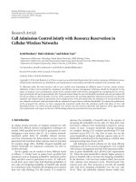
In the proposed I-EPD, jitter is observed and averaged
every 100 milliseconds at a receiver. The slope from two
averages is then calculated, and the average from five
consecutive slopes is determined. Depending on the buffer
size reserved for real-time video frames, it is wellknown that
a receiver can tolerate a certain degree of jitter. To activate the
I-EPD algorithm, when the average jitter slope is greater than
a predefined jitter tolerance (JT), an RTCP (RTP Control
Protocol) packet with payload type (PT)
= 205 is sent back
to the server along with the reverse route where the video
stream traverses. As an example, Figure 1 shows that average
jitter is ascending very fast after 5 seconds and at this moment
the average of jitter slopes has exceeded JT.
0
2000
4000
6000
8000
10000
12000
14000
16000
Jitter (1/90Ks)
012 345678910
(s)
Figure 1: Abnormal jitter detection at a receiver.
Server
Receiver
IN
i
D
1
(S,IN
i
)
D
2
(S,IN
i
)
.
.
.
D
1
(IN
i
, R)
D
2
(IN
i
, R)
.
.
.
··· ···
t
S1
t
S2
t
R1
t
R2
t
i1
t
i2
Figure 2: Delay versus jitter in video frame transmission.
2.2. Stale Frame Disc ards. Figure 2 shows two consecutive
video frames of a GOP (Group of Pictures) transmitting
fromavideoservertoareceiveratt
S1
and t
S2
,respectively.
Assume that t
i1
and t
i2
, respectively, denote the times when
these two frames are stored-and-forwarded at IN
i
,andt
R1
and t
R2
, respectively, denote the times when they arrive at the
receiver.
If we assume that the clocks of the three different nodes
(server, receiver, and IN
i
) are synchronized, then the end-to-
end jitter (delay variation) between the transmission delay of
the first video frame, D
1
(S, R), and the transmission delay of
the second video frame, D
2
(S, R), can be expressed as
End-to-end jitter between two video frames
= D
2
(
S, R
)
− D
1
(
S, R
)
=
(
t
R2
− t
S2
)
−
(
t
R1
− t
S1
)
=
(
t
R2
− t
R1
)
−
(
t
S2
− t
S1
)
,
(1)
where D
1
(S, R) = D
1
(S,IN
i
)+D
1
(IN
i
, R), and D
2
(S, R) =
D
2
(S,IN
i
)+D
2
(IN
i
, R).
After rearrangement, we have
(
t
R2
− t
R1
)
=
(
t
S2
− t
S1
)
+
(
D
2
(
S, R
)
− D
1
(
S, R
))
. (2)
Similarly, if we replace server node with IN
i
in (2), we can
derive (3):
(
t
R2
− t
R1
)
=
(
t
i2
− t
i1
)
+
(
D
2
(
IN
i
, R
)
− D
1
(
IN
i
, R
))
. (3)
EURASIP Journal on Wireless Communications and Networking 3
Server
Receiver
RTCP SR
RTCP RR
Time
RTP video packet
Phase 1
Phase 2
Phase 3
IN
i
Firstpacketofvideoframe j
Subsequent packets of
video frame j
Firstpacketofvideo
frame j +1
.
.
.
Activate I-EPD with RTCP
(ECN
= 10 and PT = 205)
De-activate I-EPD with RTCP
(ECN
= 10 and PT = 206)
T3
T1
T2
··· ···
RTP video packet
RTCP control packet
Figure 3: The proposed I-EPD with three phases.
A video frame is considered as stale if it exceeds a given
jitter tolerance (JT) after it reaches the receiver. Hence, by
substituting (3) into (1), the sufficient condition to discard a
stale video frame at any IN can be derived and it is shown in
(4):
End-to-end jitter between two video frames
= (t
R2
− t
R1
)
− (t
S2
− t
S1
) > JT,
(
t
i2
−t
i1
)
+
(
D
2
(
IN
i
, R
)
−D
1
(
IN
i
, R
))
−
(
t
S2
−t
S1
)
> JT. (4)
3. The Proposed I-EPD
3.1. RTP and RTCP Flows. In fact, the three terms of left-
hand side in (4) can be measured directly. The first term
is the time difference of forwarding two consecutive video
frames at IN
i
; the second term denotes the difference between
two transmission delays of RTP video packets from IN
i
to
the receiver; the third term is the difference between two
RTP timestamps which is equivalent to the time difference
of transmitting two consecutive video frames at a server (the
proof can be found in the appendix).
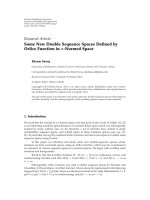
The proposed I-EPD mainly consists of three phases as
shown in Figure 3. At the beginning of Phase 1, abnormal
jitter is detected at the receiver and an RTCP control packet
with PT
= 205 is sent to the server. It is noticed that, in this
RTCP packet, we purposely set ECN (Explicitly Congestion
Notification) bits to be 10 in the IP header to activate the I-
EPD at all the intermediate nodes (IN
i
) on the path from the
server to the receiver. At the server side, once RTCP packet
with PT
= 205 is received, it sends RTCP SR (sender report)
immediately back to the receiver, which in turn responds
with RTCP RR (receiver report). Both RTCP SR and RR
will be intercepted by IN
i
for instantaneous RTT (round-
trip time) measurement. After RTT measurement, IN enters
Phase 2 and it begins to intercept the first packet of video
frame j.AscanbeseeninFigure 3, T1 denotes the time
of transmitting the first packet of frame j from IN
i
to the
receiver, T2 denotes the time difference between forwarding
two consecutive video frames (frame j and frame j +1)at
IN
i
,andT3 denotes the time of transmitting the first packet
of video frame j +1fromIN
i
to the receiver. Notice that in
the Linux implementations, both values of T1andT3canbe
calculated from one half of the measured RTT. Thus, (4), for
individual video frame, can be modified to (5), for individual
RTP packet:
T2+
(
T3
− T1
)
−
TS
frame j+1
− TS
frame j
> JT, (5)
where TS
frame j
and TS
frame j+1
, respectively, denote the two
RTP timestamps in packet headers of video frame j and
frame j + 1. To be more realistic, in the Linux implemen-
tations we should consider other network variables, such
as node queuing delay, link repair time, and different jitter
tolerances of I, B, and P frames. Thus, we have
(
T2+QD
)
+
(
T3
− T1
)
−
TS
frame j+1
− TS
frame j
+ T
RP
−
⎧
⎪
⎪
⎪
⎪
⎪
⎪
⎨
⎪
⎪
⎪
⎪
⎪
⎪
⎩
δ ×
M
FPS
,ifIframe
δ
×
N
FPS
,ifPframe
0, if B frame
> JT,
(6)
where QD denotes the average packet queuing delay that can
be directly measured at a node from Linux kernel. T
RP
is the
link repair time and it is zero if no link is broken during
the entire video transmission. Figure 4 shows an example of
GOP in MPEG compression, where M represents the number
of B and P frames between two adjacent I frames, while N
denotes the number of B frames between two adjacent P
frames. In (6), we let FPS denote video presentation rate in
frames per second and let δ denote an adjustment factor
between 0 and 1. In the Linux implementations, δ can be
adjusted at a video receiver to adapt to different network
environments.
4 EURASIP Journal on Wireless Communications and Networking
N
M
Figure 4: An Example of GOP in MPEG Compression (M =
14, N = 2).
3.2. The Three-Phase Algorithms. Algorithm 1 shows the
algorithm of Phase 1. A receiver is responsible for abnormal
jitter detection. It first calculates the average of jitters every
100 milliseconds, and then calculates the slope between two
jitters and the average of slopes every 500 milliseconds. Once
the average slope is greater than a given jitter tolerance (JT),
a receiver immediately sends out a RTCP (with ECN
= 10
and PT
= 205) packet to activate all the IN on the reverse
route of video streaming path. During the abnormal jitter
periods, the period of RTCP RR is reduced from 5 sec to
100 milliseconds; this facilitates IN to measure RTT more
effectively by considering various network conditions.
To calculate RTT more accurately, a server sends out
RTCP SR to respond to RTCP RR. After intercepting RTCP
SR and RR, an IN makes two comparisons; it first compares
the SSRC (synchronization source identifier) field of RR
to that of SR and then compares the TLSR (time of last
sender report) field of RR to the NTP time stamp of SR.
The first comparison is to make sure that the two RTCP
control packets actually belong to the same video stream
and the second comparison is to match the received RR with
the transmitted SR. If both comparisons are passed, IN then
grasps DLSR (delay since last sender report) field from RR to
calculate RTT, as shown in the second part of Algorithm 1.
Notice that DLSR is the processing delay consumed at the
receiver; it begins from the reception of SR to the sending of
RR. A video streaming server is relatively simple. Whenever
an RTCP with PT
= 205 is received, it immediately sends out
RTCP SR and reduces the period of sending RTCP SR to 100
milliseconds.
Algorithm 2 shows the algorithm of Phase 2. An IN
records two RTP timestamps after it intercepts the first packet
of frame j and j + 1, respectively. It also measures T2
(as defined in Section 3.1), which is the time gap between
the interceptions of two adjacent video frames. After the
measurement of T2, IN then computes the left-hand side of
inequality (6) and compares the result to jitter tolerance (JT).
If the result exceeds JT, the rest of packets belonging to frame
j + 1 should be discarded. Moreover, if frame j +1isI(or
P) frame, IN should drop the subsequent video packets till
the next I (or P) frame. However, if frame j +1isBframe,
IN only drops the packets belonging to this frame. Since our
experiment employs MPEG-4, an I frame usually consists of
15to20packets,aPframe5to7packets,andaBframe1to
2 packets.
Algorithm 3 shows the algorithm of Phase 3. If the
average slope is no longer greater than JT, a receiver sends
outRTCPwithECN
= 10 and PT = 206 immediately to its
server. This control packet will deactivate the I-EPD scheme
on the INs and it also resumes the period of RTCP SR and
RRbackto5seconds.
4. Implementations on Linux Platform
For the purpose of evaluation and validation, we implement
the proposed I-EPD on Linux based embedded systems as
shown in Figure 5. A video streaming server is located at one
side of a WiMAX (IEEE 802.16a) network. On the other side,
an ad hoc gateway brings in the video streams to the multi-
hop ad hoc network consisting of two embedded systems
served as IN (IN
AandINB) and one laptop PC served as
a receiver. To observe abnormal jitter at the video receiver,
background traffic is generated to produce different levels of
trafficloadonIN
B.
4.1. Performance Metrics. From the implementations, we are
interested in evaluating the following performance metrics.
(1) Percentage of received and useful frames (PRUFs).As
defined in (7), the received and useful frames are those
video frames that can meet the requirements of decoding
timestamps during the decoding process at a receiver:
PRUF
=
Received and useful video frames
Total number of video frames transmitted
.
(7)
(2) Percentage of video packets dropped (PVPD) at IN.
As defined in (8), PVPD represents the percentage of video
packet dropped at IN
Bforavideostream.PVPDisan
indicator of how much buffer spaces and wireless bandwidths
that can be saved through the proposed I-EPD:
PVPD
=
Video packets dropped at IN B
Video packets arrived at IN B
. (8)
(3) Packet drop ratio (PDR) at IN.Asdefinedin(9), PDR
represents the packet drop ratio of individual video frame
type at IN
B:
PDR
=
Packets dropped of one video frame type at IN B
Packets dropped of all video frame types at IN B
.
(9)
(4) Percentage of video frame discards (PVFDs).Asdefined
in (10)and(11), PVFD is calculated separately, one for IN
B
(PVFD
IN
), and one for video receiver (PVFD
R
):
PVFD
IN
=
Video frames discarded at IN B
Total number of video frames transmitted
,
(10)
PVFD
R
=
Received but useless video frames at receiver
Total number of video frames transmitted
.
(11)
(5) PSNR (Peak Signal-to-Noise Ratio).Tocompare
quality before and after video transmission, we define PSNR
in dB as in (12), where V
peak
= 2
k
− 1andk is the number of
bits per pixel, N
col
× N
row
represents the number of pixels
per video frame, Y
s
(i, j) is the quality value of pixel (i, j)
EURASIP Journal on Wireless Communications and Networking 5
#Video Streaming Receiver //Observe and average delay variations (jitter)
Calculates the average of jitters every 100 msec
Calculates the average of jitter slopes every 500 msec
If (average slope > jitter tolerance)
Immediately sends out RTCP packet (ECN
= 10 and PT = 205);
Sets imm
= true;
Reduces the period of RTCP RR to 100 ms;
If (imm
= true)
If(RTCPSRisreceived)
Immediately sends out RTCP RR;
imm
= false;
#Intermediate Node //RTT estimation for T1andT3
If (RTCP packet (ECN
= 10 and PT = 205) is received)
Sets intercept
= true; //intercepts RTCP SR and RR
While (intercept
= true)
If(RTCPSRisreceived)
Records SSRC and NTP timestamps of SR;
Records the system time when SR is received;
Else If (RTCP RR is received)
If (SSRC of RR
= SSRC of SR) and
(TLSR of RR
= NTP timestamp of SR)
RTT
= (system time when RR is received)
(system time when SR is received)
(DLSR of RR);
If (rtt
= false) //No previous RTT can be used
T1
= RTT/2; T3 = RTT/2;
Set rtt
= true;
Else T3
= RTT/2;
#Video Streaming Server
If (RTCP packet (ECN
= 10 and PT = 205) is received)
Immediately sends out RTCP SR;
Reduces the period of RTCP SR to 100 ms;
Algorithm 1: RTT measurement.
#Intermediate Node
//Intercepts the first packet of video frames j and j+1,respectively
While (rtt
= true) and (first packet = false)
Intercepts the first packet of video frame j;
Records its RTP timestamp;
Starts T2 timer;
Intercepts the first packet of video frame j+1;
Records its RTP timestamp;
Terminates T2 timer;
Sets first
packet = true;
//Decides whether to drop the rest of packets in video frame j+1
If (T2+QD)+(T3
− T1) − (TS
frame j+1
− TS
frame j
)+T
RP
−
⎧
⎪
⎪
⎪
⎨
⎪
⎪
⎪
⎩
δ × M/FPS, if I frame
δ
× N/FPS, ifPframe
0, if B frame
> JT
If (frame j+1is I frame)
Drops the received video packet and all the subsequent video packets
till the next I-frame packet;
Else If (frame j+1is P frame)
Drops the received video packet and the subsequent video packets
till the next P-frame packet;
Else If (frame j+1is B frame)
Drops the received video packets belonging to this B frame;
Algorithm 2: Stale packet discards.
6 EURASIP Journal on Wireless Communications and Networking
#Video Streaming Receiver //Deactivate the I-EPD
If (average slope
≤ jitter tolerance)
Immediately sends out RTCP (ECN
= 10 and PT = 206);
Resumes the period of RTCP RR to 5 sec;
#Intermediate Node
If ( RTCP (ECN
= 10 and PT = 206) is received)
Sets intercept
= false;
rtt
= false;
#Video Streaming Server
If (RTCP ((ECN
= 10 and PT = 206) is received)
Resumes the period of RTCP SR to 5 sec;
Algorithm 3: Deactivation of the I-EPD.
Video streaming server
Subscriber station (SS)
Ad hoc gateway
Video receiver
IN_A
IN_B
Background traffic
generator
Background traffic
receiver
Base station (BS)
WiMAX (802.16a)
Video streaming
Background traffic
Figure 5: Implementations of I-EPD on a Linux platform.
at sender, and Y
D
(i, j)isthatatreceiver.WhenY
s
(i, j) =
Y
D
(i, j), PSNR is set as the largest value, 99.99 dB, implying
that video quality remains unchanged after transmission:
PSNR
(
dB
)
=
20log
10
V
peak
(
1/N
col
×N
row
)
N
col
i=0
N
row
j=0
Y
S
i, j
−Y
D
i, j
2
.
(12)
4.2. Experimental Results. Ta bl es 1 and 2, respectively, show
the specifications of IN
A/IN B and MPEG-4 video streams.
Video streams are pulled with different bit rates from a
video streaming server [11] and VLC player [12] is employed
at the client. Additionally, Iperf [13]traffic is generated
in background to purposely interfere the transmitted video
streams over IN
B.
By fixing Iperf background traffic to 1 Mbps with 20%
on-off ratio, Figure 6 shows the comparison of PRUF
between the proposed I-EPD and the original model without
I-EPD. As the video bit rate is increased from 256 kbps to
1536 kbps, the difference in PRUF between the two models
increases accordingly. The number of received and useful
frames (the ones that can meet the presentation timestamps
at receiver) using I-EPD is larger than that without using I-
EPD, no matter whether FPS (frames per second) is equal to
30 or 15. This is because with I-EPD large percentage of stale
EURASIP Journal on Wireless Communications and Networking 7
Table 1: Specifications of IN A/IN B.
CPU Intel StrongARM SA-1110/206 MHz
OS Linux 2.4.0
Wireless card IEEE 802.11b Ad hoc mode
Buffer size 100 packets
0.4
0.5
0.6
0.7
0.8
0.9
1
PRUF (%)
256 512 768 1024 1280 1536
Video bit rate (Kbps)
w/o I-EPD
30
With I-EPD
30
w/o I-EPD
15
With I-EPD
15
Figure 6: Percentage of received and useful frames (PRUFs).
frames have been early discarded at IN. As a result, non-stale
video frames can utilize more buffer spaces at IN and more
bandwidth in wireless links.
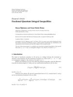
Figure 7 validates the results in Figure 6.Itisobserved
that the difference in PVPD between the two models (with
I-EPD and without I-EPD) increases as the video bit rate
is increased from 256 kbps to 1536 kbps, no matter which
FPS (15 or 30) is employed. This is because as the video
bit rate is increased, the possibility of packet discards due
to network congestion is increased. Notice that the larger
FPS, the bigger difference in PVPD. This is because network
congestion usually places more dominative effect on larger
FPSthanonsmallerone.
By fixing FPS
= 30 and setting δ = 0.5 (the adjustment
factor as in (6)), Figure 8 shows packet drop ratio (PDR)
at IN
Bfordifferent frame types and video bit rates. Since
I frame has the largest tolerance delay at receiver, its PDR
is the smallest among the three frame types. It is interesting
to notice that PDR of I (and P) frames is slightly increased,
but PDR of B-frame is decreased, as the video bit rate is
increased from 768 kbps to 1536 kbps. This is because as
network becomes congested due to larger bit rates, more
and more I (and P) frames will be dropped and one I-
frame carries about 15 times of packets more than a B-frame
does.
Figures 9 and 10, respectively, show the percentage
of video frame discards at IN (PVFD
IN
)andatreceiver
(PVFD
R
). When the video bit rate is still small (256 kbps),
almost every video frame can reach its destination in time
no matter which model (with I-EPD or without I-EPD) or
Table 2: Specifications of MPEG-4 video streams.
Resolution CIF (352 × 288 pixels)
FPS 15, 30
No. of video frames 2086, 4170
Average packet size 1300 bytes
Encoding bit rates (kbps) 256, 512, 768, 1024, 1280, 1536
0
0.05
0.1
0.15
PVPD (%)
256 512 768 1024 1280 1536
Video bit rate (Kbps)
w/o I-EPD
30
With I-EPD
30
w/o I-EPD
15
With I-EPD
15
Figure 7: Percentage of video packets dropped at IN (PVPD).
which FPS (15 or 30) is employed. However, as the bit rate
is increased to 1280 kbps, from Figure 9; we can observe that
about 8% more video frames are dropped at IN when using
I-EPD as compared to that without using I-EPD no matter
which FPS is used. Figure 10 validates the result in Figure 9,
PVFD at receiver (PVFD
R
) without using I-EPD is about 8%
bigger than the one with I-EPD. Thus, from Figures 9 and 10,
we have demonstrated that by presumably discarding stale
frames at IN the proposed I-EPD can effectively save wireless
bandwidth so that more percentages of video frames can be
delivered to the receiver in time.
Figure 11 shows the variations of PSNR, as defined
in (12), between the two models. As video is played
back at receiver, we observe that in general about 20 dB
improvements can be achieved by suing I-EPD. Figure 12
shows the impact of link repair time (LRT) on the percentage
of received and useful frames (PRUFs). LRT is defined as
the time required for the sender to recover from a link
failure. In the experiments, we assume that either IN
Aor
IN
B can move away or power down while a video stream
is transmitted over the wireless ad hoc network. As can
be seen from the figure, two different encoding bit rates
(256 kbps and 1024 kbps) are compared. As LRT increases
from 1 to 5 seconds, the gap in PRUF of the two models
(with and without I-EPD) becomes bigger; larger encoding
bit rate exhibits bigger gap even for a small LRT. This result
demonstrates that the proposed I-EPD, in comparison with
the one without I-EPD, can offer better quality for a video
stream with larger encoding bit rate and a wireless ad hoc
network with longer link repair time.
8 EURASIP Journal on Wireless Communications and Networking
0
0.1
0.2
0.3
0.4
0.5
0.6
0.7
0.8
0.9
1
PDR (%)
768 1024 1280 1536
Video bit rate (Kbps)
IFrame
PFrame
BFrame
Figure 8: Packet drop ratio at IN B (with I-EPD).
0
0.05
0.1
0.15
0.2
0.25
PVFD at IN (%)
256 512 768 1024 1280 1536
Video bit rate (Kbps)
w/o I-EPD
30
With I-EPD
30
w/o I-EPD
15
With I-EPD
15
Figure 9: PVFD
IN
versus video bit rates.
To further validate the results in Figure 12,weanalyze
the impact of LRT on the percentage of received but useless
videoframesatreceiver(PVFD
R
). As shown in Figure 13,
when LRT is increased, without I-EPD a receiver needs to
discard more video frames which although being received
but useless; the discard is about 4% more in 1024 kbps
and 8% more in 256 kbps when LRT exceeds 3 seconds.
Obviously, when a link is broken, the proposed I-EPD can
save more wireless bandwidth and improve the usage of
buffer spaces at IN. It is also interesting to notice that
without I-EPD a larger encoding bit rate produces much
smaller PVFD
R
than a smaller encoding bit rate; yet in I-
EPD different encoding bit rates only have tiny differences.
This is because when link repair time is high, larger encoding
bit rate (1024 kbps) usually encounters much higher packet
drops at IN than smaller encoding bit rate (256 kbps) does.
The higher packet dropping rate leads to smaller PVFD
R
at receiver. However, with I-EPD almost every stale video
frame is presumably discarded at IN because they cannot
meet the jitter-tolerant constraint. This explains why PVFD
R
0
0.05
0.1
0.15
0.2
PVFD at recevier (%)
256 512 768 1024 1280 1536
Video bit rate (Kbps)
w/o I-EPD
30
With I-EPD
30
w/o I-EPD
15
With I-EPD
15
Figure 10: PVFD
R
versus video bit rates.
0
20
40
60
80
100
PSNR (dB)
09.428.24765.884.6 103.4 122.2
Video presentation time (s)
w/o I-EPD
With I-EPD
Figure 11: The variations of PSNR versus video presentation time.
stays near zero no matter whether the bit rate is 1024 or
256 kbps.
4.3. Processing Overhead at IN. As illustrated in Figure 3,
an IN
i
is involved with the three-phase operation, which
may incur some processing overhead. First, an IN
i
has to
intercept three different types of packets, (i) RTCP packets
of activating and deactivating the I-EPD in the first and the
third phase, respectively, (ii) RTCP SR and RR packets every
100 milliseconds for instantaneous RTT measurements, and
(iii) the first packet of every video frame for measuring T2.
Fortunately, packet interception can be done in hardware, so
it incur very little processing time.
In addition to the packet interception, an IN
i
has to
pay some computation overhead for determining whether a
video frame is stale or not by (5). This computation cost is
also affordable by an IN
i
, since it just requires one addition
and three subtractions every 1/30 sec, if FPS (frames per
second) equals 30.
EURASIP Journal on Wireless Communications and Networking 9
Table 3: System time versus RTP timestamp at a video server.
1204735165 901009 2097329347
1204735165 901059 2097329347
1204735165 967661 2097335354
1204735165 967702 2097335354
1204735166 34259 2097341361
1204735166 34299 2097341361
1204735166 34319 2097341361
1204735166 101411 2097347368
1204735166 101448 2097347368
1204735166 101470 2097347368
1204735166 101488 2097347368
66652 us
66744 us
66598 us
67152 us
VF-1
VF-2
VF-3
VF-4
66744 us
66744 us
System time in sec
System time in usec
RTP timestamp (1/90K sec)
0.8
0.85
0.9
0.95
1
PRUF (%)
12345
Link repair time (seconds)
w/o I-EPD
256K
With I-EPD
256K
w/o I-EPD
1024K
With I-EPD
1024K
Figure 12: PRUF versus link repair time.
0
0.01
0.02
0.03
0.04
0.05
0.06
0.07
0.08
0.09
1
PVFD at receiver (%)
12345
Link repair time (seconds)
w/o I-EPD
256K
With I-EPD
256K
w/o I-EPD
1024K
With I-EPD
1024K
Figure 13: PVFD
R
versus link repair time.
5. Conclusions
This paper has presented an intelligent early packet discards
(I-EPD) scheme for jitter-tolerant video streaming over
a multi-hop wireless ad hoc network. A video packet
temporarily buffered at IN on a wireless ad hoc network may
exceed its end-to-end jitter constraint when encountering
either a congested or a failed link. The advantages of
the proposed I-EPD over the previous works are right in
that I-EPD can effectively improve buffer utilization at IN
and eliminate unnecessary bandwidth wastage in wireless
links. Two novelties and contributions of this paper are
that, (i) the proposed I-EPD can intelligently determine
whether a buffered video packet/frame should be presumably
discarded, and (ii) a mathematical equation, based on the
RTP timestamps, the time gap of receiving two adjacent
video frames at IN, and the measured round trip time by the
RTCP reports, was derived to make this intelligent decision
of discarding stale frames.
For the purpose of validation, we implement the I-
EPD scheme on a multi-hop wireless ad hoc network.
The experimental platform consists of a video server, a
receiver, and two Linux-based embedded systems. From
the experimental results, we have demonstrated that the
proposed I-EPD can significantly increase the percentage of
received and useful video frames and effectively reduce the
percentage of received but useless video frames at a receiver
for different video encoding bit rates and different link repair
times. Consequently, PSNR is significantly improved by I-
EPD.
Appendix
To validate that the difference between two RTP timestamps
is actually equivalent to the time difference of transmitting
two consecutive video frames at a server, we record system
times and capture RTP packets in the Linux implemen-
tations. As shown in Ta bl e 3, each row shows the system
times in seconds and microseconds when a video packet
10 EURASIP Journal on Wireless Communications and Networking
is transmitted and the timestamps (1/90 K sec) encoded in
the RTP header. Note that packets belong to the same
video frame (VF) are shaded in the same color for easy
understanding. From the first packet of the first video
frame (VF-1) and the first packet of the second video
frame (VF-2), we calculate their time difference, which is
equal to 66652 microseconds. On the other hand, when the
timestamp of VF-1 is subtracted from that of VF-2, it equals
6007, which after conversion is 66744 microseconds. Thus,
by simply intercepting two RTP packets from two different
video frames and calculating the difference of the two RTP
timestamps, an IN can easily acquire the time difference
when two consecutive video frames are transmitted at a
server.
References
[1]Z.Liu,G.He,andZ.Liu,“Anadaptivecontrolschemefor
real-time MPEG4 video over ad-hoc networks,” in Proceedings
of the International Conference on Wireless Communications,
Networking and Mobile Computing (WCNM ’05), vol. 2, pp.
23–26, Wuhan, China, September 2005.
[2]G.D.Delgado,V.C.Fr
´
ıas, and M. A. Igartua, “Video-
streaming transmission with QoS over cross-layered ad hoc
networks,” in Proceedings of the Internat ional Conference on
Software, Telecommunications and Computer Networks (Soft-
COM ’06), pp. 102–106, Dubrovnik, Yugoslavia, September-
October 2006.
[3] S. Mao, D. Bushmitch, S. Narayanan, and S. S. Panwar,
“MRTP: a multiflow real-time transport protocol for ad hoc
networks,” IEEE Transactions on Multimedia,vol.8,no.2,pp.
356–369, 2006.
[4] S. Mao, S. Lin, S. S. Panwar, Y. Wang, and E. Celebi,
“Video transport over ad hoc networks: multistream coding
with multipath transport,” IEEE Journal on Selected Areas in
Communications, vol. 21, no. 10, pp. 1721–1737, 2003.
[5] K. Rojviboonchai, F. Yang, Q. Zhang, H. Aida, and W.
Zhu, “AMTP: a multipath multimedia streaming protocol
for mobile ad hoc networks,” in Proceedings of the IEEE
International Conference on Communications (ICC ’05), vol. 2,
pp. 1246–1250, Seoul, South Korea, May 2005.
[6] M. Tauchi, T. Ideguchi, and T. Okuda, “Ad-hoc routing pro-
tocol avoiding route breaks based on AODV,” in Proceedings
of the 38th Annual Hawaii International Conference on System
Sciences (HICSS ’05), pp. 322–329, Big Island, Hawaii, USA,
January 2005.
[7] M. Pan, S Y. Chuang, and S D. Wang, “Local repair mech-
anisms for on-demand routing in mobile ad hoc networks,”
in Proceedings of the 11th Pacific Rim International Symposium
on Dependable Computing (PRDC ’05), p. 8, Changsha, China,
December 2005.
[8] J. Feng and H. Zhou, “A self-repair algorithm for ad hoc on-
demand distance vector routing,” in Proceedings of the Inter-
national Conference on Wireless Communications, Networking
and Mobile Computing (WiCOM ’06), pp. 1–4, Wuhan, China,
September 2006.
[9] M. Sarkar, S. Gujral, and S. Kumar, “A QoS-aware medium
access control protocol for real time trafficinadhoc
networks,” in Proceedings of the 18th Annual IEEE International
Symposium on Personal, Indoor and Mobile Radio Communica-
tions (PIMRC ’07), pp. 1–5, Athens, Greece, September 2007.
[10] P. V. Tien, “Efficient relaying of video packets over wireless
ad hoc devices,” in Proceedings of the IEEE Wireless and
Microwave Technology Conference (WAMICON ’06), pp. 1–5,
Clearwater Beach, Fla, USA, December 2006.
[11] “Darwin streaming server,” />[12] “VLC media player,” />[13] “Iperf,” />