Báo cáo hóa học: " Research Article An 802.11k Compliant Framework for Cooperative Handoff in Wireless Networks" docx
Bạn đang xem bản rút gọn của tài liệu. Xem và tải ngay bản đầy đủ của tài liệu tại đây (1.17 MB, 14 trang )
Hindawi Publishing Corporation
EURASIP Journal on Wireless Communications and Networking
Volume 2009, Article ID 350643, 14 pages
doi:10.1155/2009/350643
Research Article
An 802.11k Compliant Framework for
Cooperative Handoff in Wireless Networks
George Athanasiou,
1
Thanasis Korakis,
2
and Leandros Tassiulas
1
1
Department of Computer and Communications Engineering, University of Thessaly, 37 Glavani Street 382 21 Volos, Greece
2
Department of Electrical and Computer Engineer i ng, Polytechnic University, 5 Metrotech Center, Brooklyn, NY 11201, USA
Correspondence should be addressed to George Athanasiou,
Received 17 November 2008; Revised 16 February 2009; Accepted 9 July 2009
Recommended by Wei Li
In IEEE 802.11-based wireless networks, the stations (STAs) are associated with the available access points (APs) and communicate
through them. In traditional handoff schemes, the STAs get information about the active APs in their neighborhood by scanning
the available channels and listening to transmitted beacons. This paper proposes an 802.11k compliant framework for cooperative
handoff where the STAs are informed about the active APs by exchanging information with neighbor ing STAs. Besides, the
APs share useful information that can be used by the STAs in a handoff process. In this way, we minimize the delay of the
scanning procedure. We evaluate the performance of our mechanisms through OPNET simulations. We demonstrate that our
scheme reduces the scanning delay up to 92%. Consequently, our system is more capable in meeting the needs of QoS-sensitive
applications.
Copyright © 2009 George Athanasiou et al. This is an open access article distributed under the Creative Commons Attribution
License, which permits unrestricted use, distribution, and reproduction in any medium, provided the original work is properly
cited.
1. Introduction
The IEEE 802.11 [1] wireless local area networks (WLANs)
were originally designed to give a solution to the significant
problem of tangled cables of the end user devices. The
stations (STAs) are wirelessly connected to the available
access points (APs) and the APs are connected to a wired
backbone network. The evolution of these networks include
mesh networks where a wireless backbone is set up in order to
support end-to-end wireless user communication [2].
No matter whether the backbone is wired or wireless,
the STAs must somehow associate with an AP in order to
get network connection. During the handoff procedure, a
STA must scan all the available channels for a specific period
of time in order to be aware of all the active APs in the
neighborhood. Then, it must decide which AP is the optimal
for the handoff follow ing some optimization criteria and
start a negotiation with this AP in order to become part of
the network.
The described procedure introduces significant delays.
Under the existing technology, the STA must spend enough
time in each channel in order to be sure that it is aware
of all the available APs that operate in the specific channel.
Moreover, it must repeat this process for all available chan-
nels. The average scanning delay is 250–500 msec (depending
on the 802.11 hardware that is used) [3]. These delays
generate a significant problem in the association procedure.
The situation is even worse if we consider that the same
schemes are used in the handoff phase. Ideally, in a handoff
scenario we would like the STA to move from one cell to the
other s eamlessly. It is obvious that this is impossible with the
existing technology due to the delays we described earlier.
In this paper we propose a cooperative handoff frame-
work that can be applied in both WLANs and wireless
mesh networks, and speeds up the basic handoff procedure.
The scheme is independent from the underlying associa-
tion/handoff decision protocol that is used in the network.
In this framework we utilize mechanisms for information
sharing and radio measurement defined by 802.11k [4]. The
STAs that initialize a handoff proceduretakeadvantageof
802.11k-based mechanisms and cooperate with neighboring
STAs/APs in order to exchange significant information. In
this way we avoid sequential channel scanning and AP
probing. The main outcome of our framework is that it
2 EURASIP Journal on Wireless Communications and Networking
eliminates the delays that are introduced in the system
during the 802.11-based scanning/probe phases. Therefore,
it efficiently supports seamless STAs handoff from one cell to
another.
The rest of the paper is organized as follows. In
Section 2 we present a brief background and the state of
the art. Section 3 presents in detail our 802.11k compliant
cooperative handoff framework. In Section 4,wedescribethe
evaluation results of the proposed mechanisms. Finally, in
Section 5 we conclude and we pave the way for our future
research directions.
2. Background and Related Work
IEEE 802.11 defines association/handoff procedures based
on Received Signal Strength Report Indicator (RSSRI) mea-
surements. The unassociated STAs or the STAs that are
trying to reassociate with a new AP, initialize a scanning
process to find the available APs that are placed nearby.
During this scanning process, the STAs sequentially switch
to the available operational frequencies in order to probe
the APs and receive their information. They measure the
RSSRI values of each AP and associate with the AP that has
the highest RSSRI value (the strongest received signal). The
authentication process follows.
Several studies have proven that the RSSRI-based asso-
ciation/handoff mechanism can lead to poor network per-
formance while the networks resources are not utilized
efficiently [3, 5]. Therefore, the research community focuses
on designing new association/handoff methodologies that
will provide better resource utilization in the network. In
our previous work [6] we have introduced new dynamic
association and reassociation procedures that use the notion
of the “airtime cost” in making association/handoff decisions.
This metric reflects the uplink/downlink channel conditions
and the traffic load in the network. The cross-layer extension
of this mechanism takes into consideration the routing-
based information from the mesh backbone. Consequently,
the STAs are based on this information to optimize their
association/handoff decision.
In [7], the authors study a new STA association policy
that guarantees network-wide max-min fair bandwidth
allocation in the network. The system presented in [5]
ensures fairness and QoS provisioning in WLANs with
multiple APs. The work in [8] proposes an improved client
association and a fair resource sharing policy in 802.11
wireless networks. In [9], the authors propose an association
scheme that takes into a ccount the channel conditions
(the channel information is implicitly provided by 802.11h
[10] spe cifications). In [11] the problem of optimal user
association to the available APs is formulated as a utility
maximization problem. The work in [12] proposes a new
mechanism where the traffic is split among the available
APs in the network and the throughput is maximized
by construc ting a fluid model of user population that is
multihomed by the available APs in the network.
The papers mentioned above study optimal STA associ-
ation mechanisms in the network. On the other hand, a lot
of attention has been given in reducing the delays introduced
during the association/handoff procedure. The authors in [3]
describe in detail the main factors that cause those delays.
(i) Probe or scanning delay. During the first step in
the association/handoff procedurethatisdetermined
by 802.11 a STA have to scan for available APs:
(a) passively, by listening to their beacon frames or
(b) actively, by probing the APs. These are time
consuming procedures since the STA must scan all
the available channels (12 for 802.11a) in order
to find active APs. Further more, the STA has to
follow the beacon intervals for data synchronization
reasons. Scanning delay constitutes a major portion
of the handoff delay.
(ii) Association/Handoff delay. When a STA associates
with an AP, it has to exchange association frames with
this AP. Similarly, when a STA moves from an AP to
a new AP, it has to exchange reassociation frames with
the new AP.
(iii)
Authentication delay. A STA has to exchange authenti-
cation frames in order to be authenticated by the new
AP.
The following approaches attempt to reduce those delays
and they are closely related to our work in this paper.
The authors in [3] propose a technique to eliminate the
probe phase delay of the association process. The work in
[13] proposes a selective scanning algorithm and a caching
mechanism in order to reduce the delay introduced by the
scanning phase. Selective scanning uses a channel mask
and therefore the STAs scan a small subset of the available
channels (using this channel mask). In particular, when a
STA scans APs, a new channel mask is built based on the
current scanning status. In the next handoff, during the scan-
ning process, this channel mask will be used. Consequently,
only a well-selected subset of channels will be scanned.
In [14], the authors formulate the association problem
using neighbor and nonoverlap graphs. In [15], multiple
radios are used in order to implement more effective/fast
handoff mechanisms. Management frame synchronization
is the basic part in the proposed mechanism presented
in [16] while monitor ing of the wireless communication
links is the basic component of the proposed handoff
mechanism in [17]. In [18], the authors present a proactive
association scheme based on a distributed cache structure
that speeds up the association procedure. Another approach
that reduces the handoff delay is proposed in [ 19]. In
this work the channel scanning is performed proactively
and smart triggers reduce service disruption time in the
system. The authors in [20] present a new mesh network
architecture called SMesh. In this architecture they provide
fast handoff procedures. In [21], the authors design client-
driven handoff techniques that support vehicular mobility
in multihop wireless mesh networks. In their work, they use
channel quality measurements in the handoff decisions and
they employ mechanisms to control handoff frequency. An
interesting approach called Cooperative Roaming (CR) is
proposed in [22]. This work is very relevant to our work,
EURASIP Journal on Wireless Communications and Networking 3
Element
ID
Length
Measurement
token
Measurement
report mode
Measurement
type
Measurement
report
11111 Variable
Octets:
Figure 1: Measurement report element.
while the authors introduce cooperation in order to perform
layer 2 handoff,layer3handoff, and authentication. In their
approach the STAs subscribe to multicast groups in order to
spread useful information in the network. Our work focuses
especially on mesh networking deployments, where a large
number of clients must be supported and the provided QoS
should be high. In these highly congested environments
multicast communication is inefficient. Consequently, in our
work we follow a different approach in which we utilize
802.11k measurement techniques that are adaptively applied
in mesh deployments and can be applied in WLANs too.
Finally, in [23] there is an interesting study of different fast
handoff mechanisms.
Our work in this paper eliminates the delays in the
first part of the handoff procedures (scanning and probing
delays). It is worth mentioning that in our 802.11k compliant
client-based framework the STAs “govern” the handoff pro-
cedures. This differentiates our work from other approaches
in literature (like in [20]) where the APs are the responsible
entities for the execution of the association/handoff proce-
dures.
3. A Cooperative Handoff Framework
In this section, we present a 802.11k compliant framework
for cooperative handoff. The main contribution of this
scheme is the provisioning of fast handoff procedures that
take full advantage of the cooperation between STAs and APs
in the network. The underlying association/handoff decision
protocol can utilize the capabilities of this framework and
improve its performance. The proposed framework focuses
on wireless mesh networks where the APs communicate
through a w ireless backbone network, but it can be applied
in multicell wireless networks (WLANs) where the inter-
APs communication can be supported through their wired
connections.
3.1. IEEE 802.11k Framework. IEEE 802.11k [4]isaRadio
Resource Management standard that provides measurement
information for APs and STAs in the network. In partic-
ular, 802.11k determines Radio Measurement mechanisms
that enable STAs/APs to observe and gather data about
the radio link performance and the radio environment.
There are special Radio Measurement periods where the
STAs/APs execute these procedures in order to get informed
about the communication conditions in their neighborhood.
During those Radio Measurement periods the STAs/APs
switch to a control channel in order to communicate and
share information. Our cooperative framework exploits the
capabilities of the 802.11k-based mechanisms and provides
efficient handoff procedures. In what follows, we describe
two mechanisms that are utilized in our framework.
(i) Beacon report. ASTAcanreceiveabeacon report from
the neighboring STAs in order to be aware of the
communication conditions in its neighborhood. The
STA can operate in an active way and broadcast a bea-
con request to the neighboring STAs. Afterwards the
STA waits for a specific period (measurement period)
inordertoreceivebeacons from the neighboring
STAs. In addition, a STA can operate in a passive way
by listening to beacons that neighboring STAs send
during the measurement periods. Beacon in its pure
form carries information about the operating APs
in the neighborhood, their communication channels,
BSSID, and so forth. We must mention that 802.11k
specifies measurement periods but it does not define
the way to adjust their duration and how frequent
they are initiated. Figure 1 depicts the general format
of the measurement report defined in 802.11k stan-
dard [4], which contains the beacon report (inside the
Measurement Report field). Beacon report is depicted
in Figure 2. More information about the details of
the fields that are present in the beacon report can be
obtained in [4].
(ii) Neighbor report. In this request/response mechanism
a STA/AP can request information about the neigh-
boring APs. Neighbor report supports communica-
tion and information exchange between APs in the
network (this is not supported in beacon report).
According to 802.11k a STA/AP can initiate a neighbor
report process and send a neighbor request to the
neighboring APs. The APs that “hear” this request
react by sending a neighbor report that contains
information stored in their Management Informa-
tion Base (MIB). In addition, the APs can behave in
a passive way during a neighbor report process. In
other words during the measurement period all the
APs in the network broadcast neighbor reports
that
contain information stored in their MIB. Therefore,
an AP can “hear” the reports of its neighboring
APs without initiating a request/response procedure.
Figure 3 depicts the neighbor report element as
defined in 802.11k [4].
3.2. Proposed Framework. In our framework we support
information sharing between the STAs and the APs in the
network, based on the aforementioned mechanisms that are
defined in 802.11k. The first component in our framework
is the ad-hoc cooperative procedure that STAs use in order
4 EURASIP Journal on Wireless Communications and Networking
Regulatory
class
Channel
number
Actual measurement
start time
Measurement
duration
Reported
frame
information
811 2 1
RCPI RSNI BSSID
Antenna
ID
Parent TSF
Optional
sub-
elements
Variable
Octets:
611 1
4
Octets:
Figure 2: Beacon report.
Element
ID
Length BSSID
BSSID
information
Regulatory
class
Channel
number
PHY
type
Optional
sub-
element
Octets: 1 1 46 1 1 1 Variable
Figure 3: Neighbor report element.
to share information with their neighboring STAs. The
second component is the cooperation between the APs in
the network, where inter-AP communication is supported
and the APs share information with their neighbors. The
previous two procedures are totally independent and they
are executed during the periodic measurement periods.
Therefore, at the end of each measurement period the STAs
and the APs are aware of the operational conditions of
their neighboring STAs/APs. In case that a STA is searching
for a new AP, it initiates a cooperative handoff procedure
where the information that has been obtained during the last
measurement periods is used.
TheflowdiagramsinFigure 4 depict the main steps
of the information sharing procedures. We now give more
details about the ad-hoc cooperative information sharing
depicted in Figure 4(a) and the cooperation between the APs
depicted in Figure 4(b).
3.2.1. Ad-hoc Cooperative Information Sharing
Step 1. STA switches to the control channel and “h ears”
the beacons that the neighboring STAs send during the
measurement period. The STAs choose a random interval
and broadcast a beacon when this interval expires. Beacon
collisions are avoided by using this random interval mecha-
nism. The length of the measurement period depends on the
number of the STAs that are present in the network. During
this measurement p eriod a STA must acquire a uniform
distribution of received beacons and minimize the collisions.
The mechanism that defines the optimal measurement
period is out of the scope of his paper.
Step 2. STA receives the beacons that the neighboring STAs
send (during one measurement period). We divide the
handoff related information that the beacons carry into two
categories: (a) “objective” information: MAC address of the
APs, their operational frequencies, and so forth, and (b)
“subjective” information: communication load of the APs,
channel conditions, error rate, transmission rate, and so
forth. We call this information as “subjective” because each
STA in the network experiences its own communication
conditions and therefore it can provide a “subjective” view of
the network in its proximity. We must mention here that the
aforementioned information is stored into the basic fields of
the beacon frame, depicted in Figure 2. Additionally, several
fields can be appended in the Optional Subelements super
field. In this way the beacon frame can be extended in order to
carry extra information about the operational environment.
Step 3. For each received beacon, the STA checks the accuracy
of the “subjective” information that is carried.
Step 4. STA stores only the “accurate information”, in the way
accuracy is defined in the following discussion.
3.2.2. Cooperative Information Sharing between the APs
Step 1. APs choose a random interval and broadcast a
neighbor report when this interval expires. Neighbor report
collisions are avoided by using the random interval mecha-
nism. The measurement p eriod should be adjusted based on
the number of the APs that are present in the system, in order
to eliminate the collisions.
Step 2. APs passively “hear” the neighbor reports that the
neighboring APs send. The neig hbor reports carry “objective”
information in its information fields (Figure 3).
Step 3. APs store the received information in order to be able
to respond to a possible information request by a STA.
3.2.3. Accuracy of the “Subjective” Information. We claim that
the “subjective” information that is carried in the beacon
frames is accurate and therefore can be used by the STA
that initiated the cooperative handoff procedure when the
neighboring STAs are nearby. In other words, we support
that “subjective” information can be fully adopted in case
that the STAs are close to each other and therefore share
EURASIP Journal on Wireless Communications and Networking 5
For each neighboring STA
check: is the received
information accurate?
Measurement period
starts
Ye s
No
STA has obtained
information about its
neighboring STA
Store information
STA receives the
beacons from the
neighboring STAs
using the control
channel
More beacons?
Ye s
No
(a) Ad-hoc cooperative information sharing
Measurement period
starts
Iner-AP
communication starts
APs broadcast a
neighbor report to its
neighboring APs
APs has obtained
information about its
neighboring APs
(b) Cooperation between
the APs
Figure 4: Cooperative information sharing during the measurement periods.
similar communication conditions with each of the available
APs. An easy way to estimate the location/distance of the
neighboring STAs is to measure the Received Signal Strength
Indicator (RSSI) value of the transmitted signal. In order to
estimate the distance from the RSSI value we use free space
propagation model (line of sight) for simplicity reasons. In
indoor environments this model is not precise but is still
capable to approximate the STAs location. In free space
propagation the RSSI is determined as
P
r
(
d
)
= P
0
− 20 log
10
4πd
l
dBm
,(1)
where P
0
= 30 dBm (theoretically the maximum transmis-
sion power in 802.11), and l
= (3 ∗ 10
8
m/s)/2.4 GHz.
Figure 5 depicts the relationship between RSSI and the
distance of the STA that transmits the measured signal. In
order to measure the information accuracy, we determine
an RSSI threshold T
RSSI
. Besides, we can deal w ith the
RSSI fluctuations that occur in real-time deployments, by
measuring the mean RSSI value of the signal tr ansmitted
by a STA (we use a short window to calculate the mean
RSSI value). We assume here that the STAs/APs use the same
transmission power and there is no power control in the
system (pure 802.11 operation). This assumption arises since
we use a constant threshold T
RSSI
in our system. However,
this is not necessary because we can include the transmis-
sion power into the transmitted packet and therefore the
threshold T
RSSI
can be adapted accordingly. Furthermore, we
claim that the received information is accurate in case that
the mean RSSI value of the transmitted signal is higher than
the predefined T
RSSI
.Inparticular,RSSI helps us estimating
how far the STAs/APs that transmit are and T
RSSI
gives us
the ability to receive accurate information from the STAs/APs
that are close (and therefore it is possible that they face the
same channel conditions). In our experiments (simulation
environment) we have seen that the higher T
RSSI
values we
obtain, the more accurate this information is. T
RSSI
depends
on the conditions of each system. Therefore, the system
manager must adjust the threshold value according to the
operational conditions (indoor or outdoor environment).
We must mention here that it is difficult to predict the
radio propagation especially in indoor environments, due to
propagation effects (scattering, diffraction, reflection, etc.)
and the variability of the environment [24]. Consequently,
the accuracy of the RSSI-based distance estimation may
vary in these environments. In our framework we have
6 EURASIP Journal on Wireless Communications and Networking
024
68
10 12 14 16 18 20
Distance (m)
RSSI (dBm)
−35
−30
−25
−20
−15
−10
−5
0
5
10
15
20
−40
Figure 5: RSSI versus distance (free propagation).
used the simple approach based on the received signal, in
order to provide a baseline of the framework. Since we do
not focus on the way we will choose the criteria for the
approximation of the nodes “locality”, the simple algorithm
of using RSSI provide a lightweight system solution. Handoff
is a time-critical procedure and therefore, it must be executed
seamlessly and avoiding the effects of additional delays.
The accuracy of the RSSI-based distance estimator can be
improved in case that we use more sophisticated techniques
[25, 26].
The communication between the APs is totally “orthog-
onal” to the communication between the STAs. In particular,
in multicell WLANs the APs communicate through their
wired connections and in wireless mesh networks the APs use
the wireless backhaul to communicate. Especially in wireless
mesh networks the APs can be equipped with a second
interface for the backhaul communication (based on the
network architecture) or use separate channels. Therefore,
we can claim that the cooperative information sharing
between the APs is performed independently and in parallel
with the ad-hoc cooperative information shar ing dur ing the
measurement periods.
The main part of our framework is the cooperative
handoff mechanism that uses the information obtained from
the previous procedures and provides seamless handoffs
in the network. The flow diagram in Figure 6 depicts the
basic steps that are executed during a cooperative handoff
procedure. We describe in detail the main steps of this
mechanism.
3.2.4. Cooperative Handoff
Step 1. STA realizes that it must find a new AP (based on
the underlying association/handoff decision protocol) and
initiates a handoff procedure. So, it sends a neighbor report
request to the AP (old AP) that is currently associated with.
The neighbor report request can be imported to the probe
request frame that the STA sends in order to probe an AP
and receive useful information (in 802.11-based scanning
procedure).
Step 2. Old AP sends back a me rged neighbor report to
the STA. The merged neighbor report contains information
about its neighboring APs, which has been obtained during
the last measurement period. In particular, the merged
neighbor report use several information fields that a re part
of the Optional Subelements sup er field (Figure 3)andcarry
information for each neighboring AP. The merged neighbor
report can be incorporated into the probe response frame
that the AP sends back to the STA during the 802.11-
based scanning process. Neighbor report contains similar
information to beacon report. The main difference here is that
the neighbor report contains additional information about
“objective” characteristics of the new APs (that the STA
receives through the old AP).
Step 3. STA comes up with a handoff decision based
on the underlying association/handoff decision protocol
that is applied in the network using (a) the information
obtained during the Step 2, and (b) the information for the
neighboring APs that the STA has obtained through the ad-
hoc cooperative information sharing procedure, that was
executed during the last measurement period. We must make
clear here that in o ur framework every STA that initiates a
handoff procedure uses both types of information (a) and
(b) to come up with a handoff
decision.
An important observation here is that our cooperative
handoff mechanism gathers handoff information during a
probe request (the neighbor report request is incorporated
into the probe request)andaprobe response (the merged
neighbor report is incorporated into the probe response)
exchange between the STA and the AP. The traditional
802.11-based scanning process w astes approximately the
same time in scanning just one channel, since each STA
must keep listening to a channel for a constant time in
order to hear all the beacons that are transmitted by the
neighboring APs and then scan the next channel. Therefore,
our mechanism is much faster in gathering the information
that the STAs need and the added overhead is quite small (less
than an 802.11-based one-channel scanning). In addition,
the communication between the APs can be independently
executed (during the measurement periods) from a handoff
procedure. In this way the information from the neighboring
APs (to the old AP) will be immediately available to the STA,
when a cooperative handoff procedureisexecuted.
The ad-hoc cooperative information sharing plays an
important role in our framework since there are situations
where the old AP cannot be aware of the operational condi-
tions of all the candidate APs for association. In a mesh envi-
ronment the APs communicate over a wireless backhaul net-
work and a candidate AP could be placed out of the transmis-
sion range of the old AP. Besides, in multicell environments
a candidate AP could lose connection with the old AP or it
could belong to another subnetwork where the communica-
tion with the old AP is impossible. For example in Figure 7
we assume that STA3 is cur rently associated with AP1 and it
EURASIP Journal on Wireless Communications and Networking 7
STA initiates a
handoff
STA handoff decision
STA sends a probe
request containing
the neighbor request
to the old AP
Old AP sends back a neighbor report
(included into the probe response) containing
information about neighboring APs, that was
collected by them during the last
measurement period
STA receives the
“objective” information
for the candidate APs
through the neighbor
report
STA has obtained information
for the candidate APs during
the last measurement period
(through the ad-hoc
cooperative information sharing)
STA starts probing
the AP that is
currently associated
with (old AP)
Figure 6: Cooperative handoff procedure.
initiates a handoff process. AP1 (old AP) cannot be aware of
the operational conditions of AP2 (using the neighbor report
mechanism) because AP2 is located out of the transmission
range of AP1. In this case the STA3 receives this information
from STA4 and STA5, through the ad-hoc cooperative
procedures. Furthermore, we use ad-hoc cooperation in
order to obtain “subjective” information (uplink channel
conditions, etc.). This information cannot be obtained using
inter-AP cooperation (neighbor report ) because the APs are
not aware of these operational parameters.
If the STA decides that the “subjective” information is
accurate, then it has all the information it needs to proceed
with the handoff decision. In the opposite situation, since
the STA considers the “subjective” information as inaccurate,
it has to find a way to figure out the channel conditions
between itself and the active APs in the neighborhood. In the
existing approach, the STA could start scanning the available
channels and get measurements about the neighboring APs.
In our scheme the STA is aware of the available APs and
the channels they currently use, by exploiting the “objective”
information it has obtained. Thus, instead of scanning all
the available channels, it directly “jumps” to the active
AP1
STA3
CISCO AIRONET 350
SERIES
WIRELESS ACCESS POINT
AP3
STA4
STA1
CISCO AIRONET 350
SERIES
WIRELESS ACCESS POINT
CISCO AIRONET 350
SERIES
WIRELESS ACCESS POINT
AP2
STA2
STA5
Figure 7: Special case: cooperative handoff.
channels, saving in this way significant time and decreasing
the scanning delay.
Another issue that arises in our cooperative handoff
framework is the possible greedy behavior of the STAs that
share information about the active APs in the network. In
other words, one or more STAs can misbehave in the system
and send fake information to their neighboring STAs. In this
8 EURASIP Journal on Wireless Communications and Networking
5
10
15
20
25
30
35
40
0
200
400
500
600
800
5.5
6
7
8
9
10
×10
−3
Measurement period duration (ms)
Measurment interval (ms)
Delay (s)
Figure 8: Optimal interval values for the measurement periods
(STAs and APs follow these intervals).
way our cooperative handoff framework does not perform
effectively since it does not have the correct information.
Our scheme assumes that a trusted information exchange has
been established in the network. The issue of the trustworthy
among the stations is out of the scope of this paper and it can
be achieved using authentication techniques.
Before ending this section we must note that in our
cooperative framework we use a separate control channel for
information exchange. An interesting approach would be to
equip the STAs with a second communication interface for
information exchange. In other words, we could keep the first
interface for data communication and the second for channel
scanning and control information sharing. This approach
would gain in performance since we would avoid control
channel switching delays. However, this is not a realistic
scenario while most end user devices are not equipped
today with a second interface (cost reasons, etc.). This is
the main reason that leads us to choose control channel
communication in our framework. Nevertheless, this could
be an additional option in our framework.
4. System Evaluation
We have implemented our cooperative handoff framework
using OPNET [27]. Our mechanisms were built on top
of the IEEE 802.11 standard in order to achieve backward
compatibility. We have modified the main control frames
(beacon, probe frames) in order to simulate the basic
measurement mechanisms that are introduced by 802.11k
and incorporate the appropriate information in them. The
light modifications that we have introduced in the basic
functionality of the IEEE 802.11 standard do not affect the
performance of the network. In our simulation study we
compare our framework to the scheme proposed in [13]and
to 802.11. The work in [13] proposes a selective scanning
algorithm and a caching mechanism in order to reduce the
delay introduced by the scanning phase.
As far as the overhead and the communication cost
are concerned, it is true that our cooperative mechanisms
introduce an overhead in the performance of the network
since now the STAs/APs have to switch to the control channel
(in a periodic basis) in order to gather handoff information
from the neighbors. Besides, several control frames must be
transmitted during the periodic 802.11k-based measurement
periods in the network. However, our framework does not
introduce higher overheads and communication costs as
compared to 802.11k. As we have mentioned, our scheme
is built on top of the main mechanisms determined by the
802.11k standard and it is fully compliant with it. More
information about the performance of the 802.11k standard
can be obtained in [28]. Our simulation study takes into
account the communication costs and the extra delays that
are present in our framework, during the execution of our
mechanisms. The simulation results declare that our cooper-
ative handoff framework gains in performance as compared
to other schemes. The main reason for this improvement is
that in our framework we avoid unavailing channel scanning.
Besides, the information sharing that is introduced between
the STAs/APs during the measurement periods provide
seamless handoffs in the network, avoiding in this way large
delays and traffic interruptions. In more detail, the overhead
that our mechanisms add is approximately similar to the
overhead added by the one channel scanning procedure
which is significantly smaller than the original overhead
(in 802.11-based handoff procedure), which is equal to this
time multiplied by the number of the channels that are
scanned (more details will be g iven later in this section).
Therefore, the main outcome of this work is that the number
of the scanned channels is sig nificantly reduced (compared
to 802.11 channel scanning).
As described before, 802.11k introduces mechanisms for
information exchange during a period called measurement
period. In our scheme STAs use these mechanisms in order
to collect information related to the available APs in their
neighborhood. The duration of the measurement period as
well as how frequent the period is initiated is not defined by
the standard. In order to study how the measurement period
affects the performance of our mechanism and the overhead
that is introduced, we run several experiments on a multicell
wireless network of 5 partially overlapped cells and 65 STAs
(we give more details about the simulation environment
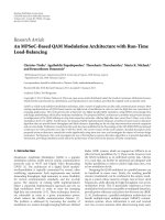
in the following subsection). Figure 8 depicts the average
transmission delay (average delay of all t ransmissions in the
system) in the system as the measurement period (x axis)
and the measurement intervals (y axis) change. As we can
see in this figure the more often the measurements are taken
place, the more accurate is the information that is exchanged.
However, the overhead increases due to frequent information
exchange in the network and the average transmission delay
is getting higher. The average transmission delay is increased
too, when the frequency of the measurements is increased
(measurement interval). Our system is not able to obtain “up
to date” information during a cooperative handoff procedure
and therefore the performance of the handoff mechanism
decreases. Additionally, large measurement periods increase
significantly the overhead too. On the other hand, when
EURASIP Journal on Wireless Communications and Networking 9
2 4 6 8 10 12 14 16 18 20
0
2
4
6
8
10
12
14
16
18
20
Real distance (m)
Estimated distance based on RSSI (m)
Figure 9: RSSI based distance estimation accuracy.
we use very small measurement periods, our mechanism
does not “have the time” to take into account the “up
to date” information that is carried in the control frames.
Consequently, the average transmission delay increases. In
Figure 8 we can observe that the optimal system opera tion
(minimum transmission delay) is achieved when the mea-
surement period lasts for 20 ms and it is initiated every
500 ms (we use these values in our simulation study). We
must mention here that the aforementioned values resulted
from our simulation study. The duration of the measurement
period and its periodicity is a system designer decision.
Therefore, the system designer must adapt the measurement
period to the properties of the system.
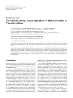
Figure 9 depicts the accuracy of the RSSI based distance
estimation used in our system. We observe that the estimated
distance is close enough to the real distance of STAs/APs that
transmit.
4.1. The Multicell Scenario. We first study a multicell 802.11g
network that consists of five partially overlapping cells.
In such simple topologies we can control the parameters
of o ur system and therefore we can have a c lear view of
the performance of the proposed protocols. The STAs are
uniformly distributed (at random) in the network and their
data frames are transmitted at 1024 kbps (we consider CBR
traffic). We vary the number of source/destination pairs in
order to vary the overall load. The source and destination
nodes are chosen randomly among the nodes in the network.
We compare the per formance of the basic 802.11-based
handoff mechanism to the performance of our 802.11k
compliant cooperative handoff framework as the communi-
cation interference changes during the network operation.
In order to effectively evaluate the performance of our
framework we consider two cases: (a) the communication
load is represented by the number of STAs that are associated
with an AP, and (b) the communication load is represented
by the airtime metric introduced in our previous work [6]
(the measured communication load in (a) and (b) is used
as described in our cooperative procedures). In particular,
the airtime cost of STA i
∈ U
a
,whereU
a
is the set of STAs
associated with AP a,is
C
i
a
=
O
ca
+ O
p
+
B
t
r
i
1
1 − e
i
pt
,
(2)
where O
ca
is the channel access overhead, O
p
is the protocol
overhead and B
t
is the number of bits in the test frame.
Some representative values (in 802.11 g networks) for these
constants are O
ca
= 335 μs, O
p
= 364 μsandB
t
= 8224 bits.
The input parameters r
i
and e
pt
are the bit rate in Mbs,and
the frame error rate for the test frame size B
t
,respectively.
More information about this metric and the underlying
association/handoff decision mechanism can be obtained in
[6]. It is clear that in the second case we take into account
channel quality information (error rate and transmission
rate), which are qualitative measurements, contrary to the
first case where we just take into account the number of the
associated STAs.
In the first simulation scenario we support 65 STAs
(uniformly distributed at random) in the multicell network.
We measure the handoff delays in the system when our
cooperative mechanism is applied in comparison to the
selective scanning algorithm proposed in [13] and to 802.11.
In particular, we measure the delay of each handoff that
is present in our system (x axis represents the handoff
number) and we calculate the average h andoff delay values.
In order to evaluate the performance of our mechanisms
we consider both stationary STAs and mobile STAs. We
use random waypoint mobility model, where the velocity is
chosen randomly between 1 and 20 m/s. Figures 10(a), 10(b),
and 10(c) depict the handoff delays during the pure 802.11-
based handoff mechanism execution, the selective scanning
algorithm application and our scheme. In this scenario the
STAs are stationary. In order to vary the channel conditions
we add interference generating jammers that are periodically
active in our system. When jammers are active, they contin-
uously transmit jamming packets that cause interference. In
this way we force the stationary STAs to handoff to a new AP,
where interference is limited. Selective scanning improves the
performance of the 802.11-based h andoff mechanism using
a channel mask, scanning in this way a small subset of the
available channels. It is clear that our system achieves lower
handoff delays due to the fact that prehandoff information is
obtained rapidly (without scanning). In Figures 11(a), 11(c)
and 11(b) we observe the handoff delays in a network that
supports random STA mobility. The outcome is similar to the
previous experiment. The proposed framework achieve quite
lower handoff delays. Tabl e 1 compares the average handoff
delays between 802.11, the selective scanning algorithm, and
our cooperative framework. An important outcome is that
our mechanisms improve the 802.11-based handoff delay
by approximately 89% when we have stationary STAs and
92% when we support mobile STAs in our system. We
allegate that this significant delay improvement will play
an important role in the improvement of the end-to-end
network p erformance. More details about this claim will be
provided in the remaining section.
During our second simulation scenario the number of
the associated STAs in the network increases from 5 to 65
10 EURASIP Journal on Wireless Communications and Networking
5 10 15 20 25 30 35 40 45 50
0
50
100
150
200
250
300
Handoff number
Delay (ms)
(a) 802.11 performance
5 10 15 20 25 30 35 40 45 50
0
50
100
150
200
250
300
Handoff number
Delay (ms)
(b) Selective scanning performance
5 10 15 20 25 30 35 40 45 50
0
50
100
150
200
250
300
Handoff number
Delay (ms)
(c) Cooperative framework performance
Figure 10: Handoff delays with stationary STAs.
5 10 15 20 25 30 35 40 45 50
0
50
100
150
200
250
300
350
400
450
Handoff number
Delay (ms)
(a) 802.11 performance
5
10 15 20 25 30 35 40 45 50
0
50
100
150
200
250
300
350
400
450
Handoff number
Delay (ms)
(b) Selective scanning performance
5
10 15 20 25 30 35 40 45 50
0
50
100
150
200
250
300
350
400
450
Handoff number
Delay (ms)
(c) Cooperative framework performance
Figure 11: Handoff delays with mobile STAs.
EURASIP Journal on Wireless Communications and Networking 11
5 101520253035404550556065
0
1
2
3
4
5
6
Number of stations
Throughput (Mbps)
(a) Average throughput
0
0.02
0.04
0.06
0.08
0.1
0.12
0.14
Delay (s)
5 101520253035404550556065
Number of stations
(b) Average transmission delay
0
1000
2000
3000
4000
5000
6000
Dropped data (bits/s)
802.11
CoopHandoff (number of stations)
CoopHandoff (airtime)
5 101520253035404550556065
Number of stations
(c) Average dropped data
Figure 12: Simulation results for the multicell scenario.
Table 1: Average Handoff delays.
Stationary STAs Mobile STAs
802.11 191 ms 303.39 ms
Selective scanning 120.96 ms 171.6 ms
CoopHandoff 20.73 ms 22.69 ms
Selective scanning improvement 36.67% 43.44%
CoopHandoff improvement 89.14% 92.52%
(STAs are uniformly placed in the network). We measure the
network throughput, the average t ransmission delay, and the
data dropping. These measurements are representative and
reflect the system performance under different operational
conditions. In order to effectively evaluate the performance
of our cooperative framework we consider two cases. The
underline association decision mechanisms use: (a) the
number of STAs as the load metric and (b) the airtime cost
as the load metric. In particular, the association decision
mechanisms avoid overloaded APs using these metrics
(where the number of the associated STAs is large in the first
case, and in the second case where the cumulative airtime
cost in the cell is high).
Figure 12(a) depicts the network throughput as the
number of the associated STAs in the network increases. We
compare the throughput values that are achieved during the
execution of the basic 802.11-based handoff scheme and our
cooperative framework. It is clear that the highest through-
put values are achieved when we apply our cooperative
handoff mechanisms since they speed up the handoff pro-
cedure. Airtime mechanism achieves the best per formance
because it takes into a ccount channel quality information for
both uplink and downlink communication and so it uses a
more representative load metric than in the case we consider
the number of STAs. In low load conditions, we observe
a quite smal l throughput improvement when we use the
proposed mechanisms. In hig h load conditions, throughput
increase is higher. The maximum throughput improvement
that is achieved by our cooperative handoff mechanism is
approximately 55% (when we have 65 associated STAs). It
is important to notice that the 802.11 network throughput is
stabilized when we have 45 associated STAs in the network.
This means that after this point the provided QoS in the
network is getting worse as the number of the STAs in
the network increases. On the other hand, our cooperative
framework expands the network capabilities and maximizes
the network throughput in presence of 65 associated STAs in
the network.
In Figure 12(b) we observe the average transmission
delay in the network. It is clear that in low load network
operation, the average transmission delay of 802.11 is quite
small and close to the average delay that is achieved by our
cooperative mechanisms. When the number of the associated
STAs increases over 35 the average delay of 802.11 is getting
extremely high. In contrary, our cooperative mechanisms
provide an additional performance improvement to the
airtime mechanism and keep the transmission delay in low
level. The 802.11-based handoff policy is quite static and
12 EURASIP Journal on Wireless Communications and Networking
2 4 6 8 10 12 14 16 18 20 22 24
0
1
2
3
4
5
6
7
8
9
×10
−3
Number of sessions
VoIP client access delay (s)
(a) Average client access delay
0
5
10
15
20
25
30
35
AP access delay (s)
2 4 6 8 10 12 14 16 18 20 22 24
Number of sessions
×10
−4
(b) Average AP access delay
0
0.01
0.02
0.03
0.04
0.05
0.06
0.07
0.08
0.09
End-to-end delay (s)
2 4 6 8 10 12 14 16 18 20 22 24
Number of sessions
802.11
CoopHandoff (number of stations)
CoopHandoff (airtime)
(c) Average end-to-end delay
0
200
400
600
800
1000
1200
1400
1600
1800
Dropped data (bits/s)
2 4 6 8 10 12 14 16 18 20 22 24
Number of sessions
802.11
CoopHandoff (number of stations)
CoopHandoff (airtime)
(d) Average dropped data
Figure 13: Average delays and dropped data in VoIP.
that causes some cells to be overloaded while the number
of the associated STAs increases. Our approach provides
fast dynamic reassociations/handoffsinordertokeepa
balanced network operation. The high 802.11 scanning
delays are avoided as our cooperative mechanism “grants”
the appropriate information to the STAs that are trying to
reassociate with new APs.
Figure 12(c) depicts the amount of packets dropped due
to channel errors and collisions in the communication. As we
can see, our mechanisms achieve lower number of dropped
packets. The sophisticated channel quality based association
policies that are introduced by the air time mechanism
and our fast cooperative reassociation procedures provide
a balanced network operation. STAs that face poor channel
conditions and high number of dropped packets, perform
fast handoffs in order to improve the network efficiency while
the underling airtime association mechanism optimizes the
STAs handoff decision.
4.2. The Mesh Network Scenario. In order to measure the
end-to-end network performance, we s tudy the application
of the proposed mechanisms in an 802.11-based wireless
mesh network. We simulated a wireless mesh network in
the OPNET simulation environment. The wireless routers
that are provided by the OPNET wireless module are part
of the backhaul network. The peripheral routers serve as
APs as well. In our simulation we use 6 peripheral routers
(mesh APs) and 4 backhaul routers (mesh Points). We
implemented RM-AODV that is introduced by 802.11s [29]
standard and we applied this routing protocol at the mesh
EURASIP Journal on Wireless Communications and Networking 13
backhaul (we can apply any QoS-aware routing protocol at
the mesh backhaul in order to evaluate our framework). The
STAs are uniformly distributed (at random) in the wireless
mesh network. For the communication between the wireless
routers in the backhaul network, we use the physical model of
IEEE 802.11a OFDM physical layer. The supported physical
rate is 12 Mbps. The STAs are associated with the available
peripheral APs. We simulated a VoIP application in the
802.11-based wireless mesh network, which is a QoS sensitive
application. In our simulations we uniformly placed several
VoIP clients in the network. We run different simulation
scenarios where we varied the number of the VoIP sessions
that are supported in parallel.
First of all we measured the average local client access
delay in the network. In practice, this delay reflects the time
that the packet is generated until it leaves the client interface.
The number of the sessions that are supported in parallel
increases from 2 to 24. Figure 13(a) depicts the average VoIP
client access delay. Our cooperative mechanism (with the
airtime metric) achieves lower client access delays in the
network. Consequently, our cooperative framework provides
fast handoff procedures and keeps the client access delay
in low level. The tr aditional 802.11 operation overloads the
network and therefore increases significantly the access delay
of the clients. In high load conditions, the delay improvement
that is introduced by our mechanism is very high.
Figure 13(b) depicts the average local AP access delay in
the network. This delay is the time passed from the arrival
of a VoIP packet at the AP until the moment that it is either
successfully transmitted over the wireless mesh network or
dropped. As we see we get similar results to those of the
client access delay. In pure 802.11 the overloaded APs (in
high load conditions) have a lot of traffictoforwardto
the mesh backhaul network. The main consequence is that
the VoIP packets have to wait for a long time to be trans-
mitted by the APs, introducing in this way high AP access
delays.
In Figure 13(c) we observe the average end-to-end delay
in the VoIP packet transmission. The end-to-end delay is
affected by the previous two kinds of delays that we have
described and the routing delay that is introduced in the
backhaul network. In our cooperative framework we achieve
low end-to-end delays in the network. Especially in the
airtime mechanism operation the delay improvement is
very high. This improvement is true due to the fast VoIP
clients/APs access in the network and the fast handoff that
is provided. We allegate that the most interesting result is
depicted in Figure 13(c), where the pure 802.11 operation
can support at most 14 sessions in parallel while our
cooperative framework supports 24 sessions. Therefore, we
have a network performance improvement of approximately
66%.
The last figure (Figure 13(d)) depicts the dropped pack-
ets during the operation of the mesh network. Channel
errors and packet collisions are the main reasons for this
packet dropping. In 802.11 the number of dropped packets
is high. Our proposed mechanisms decrease this number and
manage to keep it low even in high load conditions.
Concluding this section we summarize the key achieve-
ments of our cooperative framework that are highlighted in
our evaluation study:
(i) adaptability of the measurement mechanisms defined
in 802.11k
(ii) lower handoff delays, compared to 802.11 and to
selective scanning approach
(iii) seamless mobility management in the network
(iv) efficient scalability and network performance in
wireless multicell environments
(v) support of QoS-sensitive applications in dynamic
wireless mesh environments.
5. Conclusions
In this paper we propose a new handoff framework that
introduces cooperation between STAs/APs. Our cooperative
framework is compliant to 802.11k and it utilizes informa-
tion exchange and measurement mechanisms that are speci-
fied in the standard in order to eliminate the scanning/probe
delays in the handoff process. The proposed mechanisms
work independently of the underling association/handoff
procedures and therefore they can be applied in combination
to any association/handoff protocol. Besides, the proposed
mechanisms in this framework can be applied to 802.11-
based WLANs and wireless mesh networks. Our main
contributions in the current research field are
(i) an 802.11k compliant cooperative handoff frame-
work for wireless networks
(ii) two cooperative schemes that take full advantage of
the mechanisms that 802.11k provides
(iii) extensive simulation experiments where we support
QoS sensitive applications. We evaluate the perfor-
mance of our framework by applying different under-
lying handoff decision protocols and we measure the
performance improvement that is achieved.
Our future directions include the implementation of
these mechanisms using Linux open source drivers and the
evaluation of our system in real conditions.
References
[1] IEEE 802.11, “Wireless LAN medium access control (MAC)
and physical layer (PHY) specifications,” ANSI/IEEE Std
802.11, 1999 Edition.
[2] I. F. Akyildiz, X. Wang, and W. Wang, “Wireless mesh
networks: a survey,” Computer Networks,vol.47,no.4,pp.
445–487, 2005.
[3] A. Mishra, M. Shin, and W. Arbaugh, “An empirical analysis
of the IEEE 802.11 MAC layer handoff process,” ACM
SIGCOMM Computer Communication Review, vol. 33, no. 2,
pp. 93–102, 2003.
[4] IEEE 802.11 WG, “Wireless medium access control (MAC)
and physical layer (PHY ) specifications: specification for radio
resource measurement, IEEE 802.11k/D3.0,” New York, NY,
USA: The Institute of Electrical and Electronics Engineers,
Inc., October 2005.
14 EURASIP Journal on Wireless Communications and Networking
[5] Y Bejerano and R. Bhatia, “Mifi: a framework for fairness and
QoS assurance in current IEEE 802.11 networks with multiple
access points,” in Proceedings of the Annual Joint Conference
of the IEEE Computer and Communications Societies (INFO-
COM ’04), Hong Kong, 2004.
[6] G. Athanasiou, T. Korakis, O. Ercetin, and L. Tassiulas,
“Dynamic cross-layer association in 802.11-based mesh
networks,” in Proceedings of the Annual Joint Confer-
ence of the IEEE Computer and Communications Societies
(INFOCOM ’07), pp. 2090–2098, Anhcorage, Alaska, USA,
May 2007.
[7] Y. Bejerano, S. Han, and L. Li, “Fairness and load balancing
in wireless lans using association control,” in Proceedings of
the Annual International Conference on Mobile Computing and
Networking (MOBICOM ’04), Philadelphia, Pa, USA, 2004.
[8] B. Kauffmann, F. Baccelli, A. Chaintreau, V. Mhatre, K. Papa-
giannaki, and C. Diot, “Measurement-based self organization
of interfering 802.11 wireless access netwroks,” in Proceedings
of the Annual Joint Conference of the IEEE Computer and Com-
munications Societies (INFOCOM ’07), Anhcorage, Alaska,
USA, May 2007.
[9] T. Korakis, O. Ercetin, S. Krishnamurthy, L. Tassiulas, and
S. Tripathi, “Link quality based association mechanism in
IEEE 802.11h compliant wireless LANs,” in Proceedings of
the Workshop on Resource Allocation in Wireless Networks
(RAWNET ’05), April 2005.
[10] IEEE 802.11h, “Wireless LAN medium access control (MAC)
and physical layer (PHY) specifications: spectrum and trans-
mit power management extentions in the 5 GHz band in
Europe”.
[11] A. Kumar and V. Kumar, “Optimal association of stations and
APs in an IEEE 802.11 WLAN,” in Proceedings of the National
Conference on Communications (NCC ’05), IIT, Kharagpur,
India, January 2005.
[12] S. Shakkottai, E. Altman, and A. Kumar, “The case for non-
cooperative multihoming of users to access points in IEEE
802.11 WLANs,” in Proceedings of the 25th Annual Conference
of the IEEE Computer and Communications Societies (INFO-
COM ’06), Barcelona, Spain, April 2006.
[13] S. Shin, A. G. Forte, A. S. Rawat, and H. Schulzrinne, “Reduc-
ing MAC layer handoff latency in IEEE 802.11 wireless LANs,”
in Proceedings of the 2nd International Workshop on Mobility
Management and Wireless Access Protocols (MobiWac’04),pp.
19–26, ACM, 2004.
[14] M. Shin, A. Mishra, and W. A. Arbaugh, “Improving the
latency of 802.11 hand-offs using neighbor graphs,” in Pro-
ceedings of the 2nd International Conference on Mobile Systems,
Applications and Serv ices (MobiSys’04), pp. 70–83, New York,
NY, USA, June 2004.
[15] V. Brik, A. Mishr a, and S. Banerjee, “Eliminating handoff
latencies in 802.11 WLANs using multiple radios: appli-
cations, experience, and evaluation,” in Proceedings of the
Internet Measurement Conference (IMC ’05), ACM/USENIX,
October 2005.
[16] I. Ramani and S. Savage, “SyncScan: practical fast handoff for
802.11 infrastructure networks,” in Proceedings of the Annual
Joint Conference of the IEEE Computer and Communications
Societies (INFOCOM ’05) , vol. 1, pp. 675–684, March 2005.
[17] V. Mhatre and K. Papagiannaki, “Using smart triggers for
improved performance in 802.11 networks,” in Proceedings of
the 4th International Conference on Mobile Systems, Applica-
tions and Services (MobiSys ’06), pp. 246–259, June 2006.
[18] A. Mishra, M. Shin, and W. Arbaugh, “Context caching using
neighbor graphs for fast handoffs in a wireless network,”
in Proceedings of the Annual Joint Conference of the IEEE
Computer and Communications Societies (INFOCOM ’04),pp.
351–361, Hong Kong, March 2004.
[19] H. Wu, K. Tan, Y. Zhang, and Q. Zhang, “Proactive scan:
fast handoff with smart triggers for 802.11 wi reless LAN,”
in
Proceedings of the Annual Joint Conference of the IEEE
Computer and Communications Societies (INFOCOM ’07),
Anhcorage, Alaska, USA, May 2007.
[20] Y. Amir, C. Danilov, M. Hilsdale, R. Musaloiu-Elefteri, and N.
Rivera, “Fast handoff for seamless wireless mesh networks,”
in Proceedings of the 4th International Conference on Mobile
Systems, Applications and Services (MobiSys ’06), pp. 83–95,
ACM, Uppsala, Sweden, June 2006.
[21] A. Giannoulis, M. Fiore, and E. W. Knightly, “Supporting
vehicular mobility in urban multi-hop wireless networks,” in
Proceedings of the International Conference on Mobile Systems,
Applications and Services (MobiSys ’08), ACM, 2008.
[22] A. G. Forte and H. Schulzrinne, “Cooperation between
stations in wireless networks,” in Proceedings of the Interna-
tional Conference on Network Protocols (ICNP’07), pp. 31–40,
Beijing, China, October 2007.
[23] S. Pack, J. Choi, T. Kwon, and Y. Choi, “Fast handoff support
in IEEE 802.11 wireless networks,” in Proceedings of the IEEE
Communications Surveys & Tutorials (CST ’06), August 2006.
[24] K. Pahlavan and P. Krishnamurthy, Principles of Wireless
Networks: A Unified Approach, Prentice Hall PTR, Upper
Saddle River, NJ, USA, 2002.
[25] P. Bahl and V. N. Padmanabhan, “RADAR: an in-building
RF-based user location and tracking system,” in Proceedings
of the Annual Joint Conference of the IEEE Computer and
Communications Societies (INFOCOM ’00), Tel-Aviv, Israel,
2000.
[26] K. Kaemarungsi and P. Krishnamurthy, “Modeling of indoor
positioning systems based on location fingerprinting,” in Pro-
ceedings of the Annual Joint Conference of the IEEE Computer
and Communications Societies (INFOCOM ’04), Hong Kong,
2004.
[27] OPNET, , Radio/Wireless Models.
[28] S. Mangold, Z. Zhong, G. R. Hiertz, and B. Walke, “IEEE
802.11e/802.11k wireless LAN spectrum awareness for dis-
tributed resource sharing. Special issue on emerging WLAN
technologies and applications,” in Wireless Communications
and Mobile Computing, John Wiley & Sons, New York, NY,
USA, 2004.
[29] IEEE 802.11s, “Wireless LAN medium access control (MAC)
and physical layer (PHY) specifications: simple efficient
extensible mesh (SEE-Mesh) proposal”.