Báo cáo hóa học: " Research Article Distributed Range-Free Localization Algorithm Based on Self-Organizing Maps" pdf
Bạn đang xem bản rút gọn của tài liệu. Xem và tải ngay bản đầy đủ của tài liệu tại đây (1.46 MB, 9 trang )
Hindawi Publishing Corporation
EURASIP Journal on Wireless Communications and Networking
Volume 2010, Article ID 692513, 9 pages
doi:10.1155/2010/692513
Research Article
Distributed Range-Free Localization Algorithm Based on
Self-Organizing Maps
Pham Doan Tinh and Makoto Kawai
Graduate School of Science and Engineering, Ritsumeikan University, 1-1-1 Noji Higashi, Kusatsu, Shiga 525-8577, Japan
Correspondence should be addressed to Pham Doan Tinh,
Received 28 August 2009; Accepted 21 September 2009
Academic Editor: Benyuan Liu
Copyright © 2010 P. D. Tinh and M. Kawai. This is an open access article distributed under the Creative Commons Attribution
License, which permits unrestricted use, distribution, and reproduction in any medium, provided the original work is properly
cited.
In Mobile Ad Hoc Networks (MANETs), determining the physical location of nodes (localization) is very important for many
network services and protocols. This paper proposes a new Distributed Range-Free Localization Algorithm Based on Self-
Organizing Maps (SOMs) to deal with this issue. Our proposed algorithm utilizes only connectivity information to determine
the location of nodes. By utilizing the intersection areas between radio coverage of neighboring nodes, the algorithm has
maximized the correlation between neighboring nodes in distributed implementation of SOM and reduced the SOM learning
time. An implementation of the algorithm on Network Simulator 2 (NS-2) was done with the mobility consideration to verify the
performance of the proposed algorithm. From our intensive simulations, the results show that the proposed scheme achieves very
good accuracy in most cases.
1. Introduction
Recently, mobile ad-hoc network localization has received
attention from many researchers [1]. Many algorithms and
solutions have been presented so far. These algorithms are
ranging from simple to complicated schemes, but they can
be categorized as range-based and range-free algorithms.
Range-free algorithms utilize only connectivity information
and the number of hops between nodes. The others utilize
the distance measured between nodes by either using the
Time-Of-Arrival (TOA) [2], Time-Differential-Of-Arrival
(TDOA) [3], Angle-Of-Arrival (AOA) [4], or Received-
Signal-Strength-Indicator (RSSI) [5] technologies. However,
they usually need extra hardware to achieve such mea-
surement. When calculating the absolute location, most
schemes need at least three anchors (nodes that are equipped
with Global Positioning System or know their location in
advance).
DV-HOP is a typical range-free algorithm. It was pro-
posed by Niculescu and Nath [6] as an Ad-hoc Positioning
System (APS). DV-HOP uses distance-vector forwarding
technique to get the minimum hop count from a node to
heard anchors. By using corrections calculated by anchors
(average hop-distance between anchors), nodes estimate
their location by using lateration (triangulation) method.
Besides DV-HOP, some other algorithms seem to be more
complicated, but have better accuracy. The Multidimensional
Scaling Map (MDS-MAP) proposed by Shang et al. [7]is
an example. MDS-MAP is originated from a data analytical
technique by displaying distance-like data in geometrical
visualization. It computes the shortest paths between all pairs
of nodes to build a distance matrix and then applies the
classical Multidimensional Scaling (MDS) to this matrix to
retain the first two largest eigenvalue and eigenvector to a
2D relative map. After that, with three given anchors, it
transforms the relative map into an absolute map based
on anchors’ absolute location. There are some variances
of MDS-MAP such as centralized method: MDS-MAP(C),
and distributed one: MDS-MAP(P). But, in the distributed
method, to get the absolute location, nodes need global
information about the subnetwork’s map that contains
at least three anchors. Tran and Nguyen [8]proposeda
new localization scheme based on Support Vector Machine
(SVM). The authors have contributed another machine
learning method to the localization problem, and proved the
upper bound error of this method.
2 EURASIP Journal on Wireless Communications and Networking
Regarding the localization based on Self-Organizing
Maps, some researchers have employed SOM directly or with
some modification. The method presented by Giorgetti [9]
employed the classical SOM to the localization. This method
uses centralized implementation and requires thousands of
learning steps in convergence of network topology. The
authors also realize that this method is good for small and
medium size networks of up to 100 nodes. S. Asakura et
al. proposed a distributed localization scheme [10]based
on SOM. Hu and Lee [11] also proposed another version
of distributed localization based on SOM. In this work, the
authors employed a deduced SOM version [12]. But, this
method still needs too many iterations (at least 4000) to make
the topology to be converged with a relatively low accuracy.
In another work [13], the authors use SOM to track a mobile
robot with the utilization of surrounding environments from
readings of sensor data. In the work presented by Ertin
and Priddy [14], another version of SOM was used to
implement the localization in wireless sensor networks. This
paper extends one of our previous work [15]toimprove
and adapt it with mobility scenarios. The main contribution
of this paper is the utilization of intersection between radio
coverage of neighboring nodes in our modified SOM, and
the adaptation of the algorithm to the mobility scenarios. It
is also noted that our method was verified in both MATLAB
and NS-2 environments.
2. Motivation for Distributed
SOM-Based Localization
2.1. Self-Organizing Maps. The Self-Organizing Maps
(SOMs) were invented by Kohonen [16]. SOM provides
a technique for representation of multidimensional data
into much lower-dimensional spaces (usually one or two
dimensions). It uses a process known as vector quantization.
The nature of SOM is a neural network working in
unsupervised learning manner. The SOM learning process
canbesummarizedasfollows.
(1) Initialization: assign the initial weight, w
i
,toeach
neuron in the SOM network.
(2) Finding the BMU: determine the Best Matching Unit
(BMU) or winning neuron j
∗
at the iteration k by
using Euclidean minimum-distance criterion:
j
∗
= argmin|x
(
k
)
−w
i
(
k
)
|, i = 1, , N,
(1)
where x(k)
= [x
1
(k), , x
n
(k)]
T
represents the k −th
input pattern, N is the total number of SOM neurons,
and the input pattern has n dimensions.
(3) Weight adjusting: Adjust the weights of the BMU and
its neighbors using the following rule
w
j
(
k +1
)
= w
j
(
k
)
+ Θ
(
k
)
L
(
k
)
x
(
k
)
−w
j
(
k
)
(2)
where L(k) is the learning rate at time step k-th and
Θ(k) is the function for topological neighborhood of
neuron j
∗
at time step k-th.
Steps 2 and 3 are repeated until the convergent criterion is
satisfied.
2.2. Motivation for Distributed SOM-Based Localization.
Suppose that we have a mobile ad-hoc network of connected
nodes, in which only a small number of nodes know
their location in advance (anchor nodes). Now we have
to determine the location of the remaining nodes that do
not know their location, especially in distributed manner.
In our proposed scheme, one can think that a mobile
ad-hoc network itself is an SOM network, in which each
neuron is a node in that network, and these neurons are
connected to their 1-hop neighboring nodes (nodes have
direct radio links). The topological position and the weight
of each neuron are associated with its estimated location. The
learning process takes place locally at each node, where the
input pattern is estimated location of the node (this input is
dynamically changed over time except that the anchors use
their known location). The neighborhood neurons of a node
are determined by its 1-hop neighboring nodes. It is obvious
that each node becomes the Best-Matching Unit (BMU) at its
local region. So when updating weights at the BMU, only its
1-hop neighbors’ weights are updated. The BMU node also
receives updates from other nodes when it becomes 1-hop
neighbor of other nodes. Anchors do not update their known
positions during the learning process, so if the network has
some nodes know their location in advance (anchors), then
each node will utilize the information from these anchors by
adjusting its location towards the estimated absolute location
based on the information from these heard anchors. At the
end of the learning process, the weight at each node (SOM
neuron) is its estimated location.
3. Proposed Distributed Localization Algorithm
Based on SOM
In this section, we will introduce about our proposed Dis-
tributed Range-free Localization Algorithm (LS-SOM). The
first two sections describe about initialization and learning
stages of the main algorithm. The mobility consideration is
presented in the third section.
3.1. Initialization Stage. In the initialization stage, each
anchor in the network broadcasts a packet to its neighboring
nodes. This packet contains the anchor’s location and a hop
count initialized to one. When a node receives a packet that
contains anchor information, node then decides to discard
or forward the packet to its neighboring nodes or not with
the following rules.
(1) If the packet is already in the cache, the node then
compares the hop count of the packet with that of
the cached packet. If the hop count of the arrival
packet is less than that of the cached packet, then the
cached packet is replaced with a new arrival packet,
and forwarded to its neighboring nodes with hop
count modified to add one hop. If the hop count of
the arrival packet is greater than or equal to that of
cached packet, then it is dropped.
EURASIP Journal on Wireless Communications and Networking 3
i
k
j
j
j
i
k
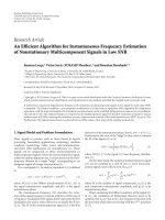
Figure 1:Thecasewherenode
j
has wrong estimated location.
i
i,j1
i,j2
i
, j
i, j
2
i, j
1
i, j
i
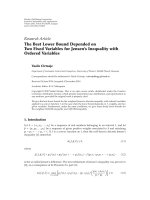
Figure 2: Possible location of neighboring node
i,j
.
(2) If the packet is not in the cache, then it is added to the
cache and forwarded to its neighboring nodes with
hop count modified to add one hop.
Having information from some anchors, the nodes now
initialize their location ready for SOM learning process.
In our proposed method, the initial location of a node
is calculated based on either randomized value (if node
does not receive enough information from three anchors)
or a value calculated using a trilateral method. In this
initialization stage, nodes also exchange information (using
short “HELLO” message broadcast) so that each node has
information about its neighboring nodes (1-hop neighbors).
Each node also exchanges information about 1-hop neigh-
bors (just the IDs of 1-hop neighbors) with its neighboring
nodes, so that all nodes in the network have information
about both 1-hop and 2-hop neighboring nodes.
3.2. Learning Stage. Before going into our algorithm details,
let us formulate the mathematical notations which will
be used in this paper. We represent a wireless ad-hoc
network as an undirected connected graph. The vertices are
(
ij
−
ij,k
)
ij
has wrong location
ij
ij
i,j,k
i
i, ji, j
i
ij
correct location
i, j, k
y
x(0.0)
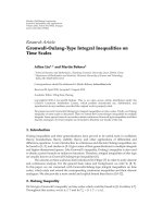
Figure 3: The case where neighboring node
i,j
is located at wrong
location.
Start LS-SOM
Anchors broadcast &
initalize LS-SOM parameters
Unknown node has
information from 3 anchors?
Initialize location using
random method
Initialize location using
trilateral method
Neighborhood
information is expired?
Neighborhood detection
using ‘HELLO’ messages
Perform SOM
learning at step m-th
m
= m +1 Resetm = 1
m
≥ T?
No Yes
No
Ye s
No Yes
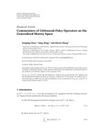
Figure 4: Repeated learning in mobile environment.
nodes’ locations, and edges are the connectivity information
(direct connection between neighboring nodes). The target
wireless ad-hoc network is formed by G anchors with known
locations Ω
i
(i = 1,2, , G) and N nodes with unknown
locations. The unknown nodes have actual locations denoted
4 EURASIP Journal on Wireless Communications and Networking
0.1
0.2
0.3
0.4
0.5
0.6
0.7
0.8
Mean error (R)
7 8 9 1011121314
Connectivity
Known HOP, random, 100 nodes, 10 anchors
MDS-MAP(C)
MDS-MAP(P)
LS-SOM
SOM
DV-HOP
Figure 5: Performace by connectivity.
0.2
0.25
0.3
0.35
0.4
0.45
0.5
Mean error (R)
4 6 8 10121416
Number of anchors
Known HOP, random, 100 nodes, connectivity
= 10.18
MDS-MAP(C)
MDS-MAP(P)
LS-SOM
SOM
DV-HOP
Figure 6: Performace by anchors.
as ω
i
(i = 1, 2, , N) and estimated locations denoted as
i
(i = 1, 2, , N).
(1) Estimated location exchange: at this step, each node
forwards its estimated location to all of its neighbors, so
that it also knows the estimated location of its neighbors as
i,j
(j = 1, 2, , N
i
)withN
i
is the number of nodes within
its communication range.
(2) Local update of relative location: we will now shape
the topology at each region formed by the node with location
i
together with all of its neighboring nodes. The node
0.15
0.2
0.25
0.3
0.35
Mean error (R)
0 5 10 15 20 25 30 35 40 45
50
Total SOM learning steps
Figure 7: Performace by SOM learning steps.
with location
i
plays as the input vector and becomes
the winning neuron for that region. Consequently, the
neighboring nodes of the node with location
i
will receive
the updating vector from node with location
i
. Suppose that
the node with the estimated location
i
has N
i
neighbors.
The locations of these neighbors are denoted as
i,j
(j =
1, ,N
i
). Based on classical SOM, neighboring nodes of
the node with location
i
will update their weight with the
following formula:
i,j
(
m +1
)
=
i,j
(
m
)
+ Δ
(
m
)
,
(3)
where Δ(m) is calculated using
Δ
(
m
)
= α
(
m
)
i
−
i,j
(
m
)
,(4)
in which α(m) is the learning rate exponential decay function
at iteration m
−th defined in (5).
α
(
m
)
= exp
−
m +1
T
(5)
where m denotes the m-th time step of the total T learning
steps. But, updating by using (3) means that the neighboring
nodes will move toward the location determined by
i
.
This will lead to the problem as showed in Figure 1.From
Figure 1, the nodes with location
j
and
k
are the neighbors
of the node with location
i
,but
j
is not the neighbor of
k
. In the worst case, the estimated location of the node
with location
j
falls into the radio range of the node with
location
k
, then the node with location
j
may not escape
from that wrong location throughout the learning process
(dead location) as illustrated by position j
.
In this paper, we propose an algorithm to solve this
problem as follows. Suppose that at the node with location
i
, we have to update location for the neighbor node with
location
i,j
(j = 1, , N
i
). First, we find out other L
i,j
neighboring node
i,j,k
(k = 1, , L
i,j
) of the node with
location
i
that are not the neighbor of the node with
location
i,j
(this is done easily because each node knows
its neighbors’ neighbors) and find their estimated location
EURASIP Journal on Wireless Communications and Networking 5
0
1
2
3
4
5
6
7
8
9
10
11
12
13
14
15
16
17
18
19
20
21
22
23
24
25
26
27
28
29
30
31
32
33
34
35
36
37
38
39
40
41
42
43
44
45
46
47
48
49
50
51
52
53
54
55
56
57
58
59
60
61
62
63
64
65
66
67
68
69
70
71
72
73
74
75
76
77
78
79
80
81
82
83
84
85
86
87
88
89
90
91
92
93
94
95
96
97
98
99
1
2
3
4
5
6
7
8
9
246 8
(a)
0
1
2
3
4
5
6
7
8
9
10
11
12
13
14
15
16
17
18
19
20
21
22
23
24
25
26
27
28
29
30
31
32
33
34
35
36
37
38
39
40
41
42
43
44
45
46
47
48
49
50
51
52
53
54
55
56
57
58
59
60
61
62
63
64
65
66
67
68
69
70
71
72
73
74
75
76
77
78
79
80
81
82
83
84
85
86
87
88
89
90
91
92
93
94
95
96
97
98
99
1
2
3
4
5
6
7
8
9
10
024 68
(b)
0
1
2
3
4
5
6
7
8
9
10
11
12
13
14
15
16
17
18
19
20
21
22
23
24
25
26
27
28
29
30
31
32
33
34
35
36
37
38
39
40
41
42
43
44
45
46
47
48
49
50
51
52
53
54
55
56
57
58
59
60
61
62
63
64
65
66
67
68
69
70
71
72
73
74
75
76
77
78
79
80
81
82
83
84
85
86
87
88
89
90
91
92
93
94
95
96
97
98
99
1
2
3
4
5
6
7
8
9
246 8
(c)
0
1
2
3
4
5
6
7
8
9
10
11
12
13
14
15
16
17
18
19
20
21
22
23
24
25
26
27
28
29
30
31
32
33
34
35
36
37
38
39
40
41
42
43
44
45
46
47
48
49
50
51
52
53
54
55
56
57
58
59
60
61
62
63
64
65
66
67
68
69
70
71
72
73
74
75
76
77
78
79
80
81
82
83
84
85
86
87
88
89
90
91
92
93
94
95
96
97
98
99
0
1
2
3
4
5
6
7
8
9
246
8
(d)
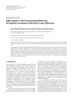
Figure 8: Topology regeneration (N = 100, G = 4, connectivity = 4.88): (a) actual topology, (b) DV-HOP (error = 0.50), (c) SOM (error =
0.35), (d) LS-SOM (error = 0.23).
falls into radio range of the node with location
i,j
.Now
we calculate the vector that has the direction towards the
intersection area as illustrated by the dashed area in Figure 2.
As illustrated in Figure 3, this vector is calculated using
ξ
i,j
=
1
L
i,j
L
i,j
k=1
R −
i,j
−
i,j,k
i,j
−
i,j,k
i,j
−
i,j,k
,(6)
where R denotes the maximum communicable range
between node with location
i,j
and node with location
i,j,k
(k = 1, ,L
i,j
). We use vector ξ
i,j
as a guidance
to update the location of the node with location
i,j
by
changing (3)to(7),
i,j
(
m +1
)
=
i,j
(
m
)
+ Δ
(
m
)
+
|Δ
(
m
)
|
⎛
⎝
ξ
i,j
ξ
i,j
⎞
⎠
β.
(7)
The update by (7) makes each node move toward the
intersection area as showed in Figure 2. This update also
maximizes the correlation between the neighboring nodes
that is the key problem for the speed and accuracy of
topological convergence using SOM. In (7), β is a learning
bias parameter calculated using
β
=
⎧
⎨
⎩
0, m<= τ,
1, m>τ,
(8)
with τ is a learning threshold. This threshold determines the
step to apply this modification. Basically, we can apply this
modification after several steps of SOM learning when nodes
are in relative order to ensure the convergence of the learning
process. At the end of this step, the node with location
i
transmits its neighbor location updates based on (7)toallof
6 EURASIP Journal on Wireless Communications and Networking
1
2
3
4
5
6
7
8
9
24 68
100 nodes, R
= 2, connectivity = 10.18
Figure 9: An actual random deployment topology.
its neighbors. As a result, it also receives the similar updates
from its N
i
neighboring nodes as
j,i
(j = 1, , N
i
). Node
with location
i
now calculates its newly estimated location
by averaging its current location and the updates from the
neighboring nodes using
i
=
1
N
i
+1
⎛
⎝
N
i
j=1
j,i
+
i
⎞
⎠
.
(9)
The learning process is repeated T times.
3.3. Mobility Consideration. In MANETs, nodes may move
in arbitrarily manner, so the movement of nodes will affect
the performance of the algorithm. To adapt LS-SOM with
MANETs, we proposed a repeated learning algorithm as
follows.
(1) First Time Initialization. Anchors participate in
localization will flood the network just one time, so that
nodes can calculate the initial location for fast topology
convergence.
(2) Repeated Learning. At specified interval, nodes per-
form neighboring detection by exchanging short “HELLO”
messages. Having neighboring information, nodes now
proceed with the learning process.
The algorithm is illustrated by the flowchart in Figure 4.
4. Simulation Evaluations
To evaluate the performance of our proposed method, we use
the average error ratio in comparison with the radio range of
the nodes presented in
Error
(
R
)
=
1
N
N
i=1
|
i
−ω
i
|
R
.
(10)
4.1. Simulation Parameters. To ease the comparison, we call
the method in the existing work [10]asSOM,andourpro-
posed method as LS-SOM. We conducted the simulation for
static and mobile scenarios by using MATLAB (we integrated
SOM, DV-HOP, and LS-SOM into the program received
from [7]) and NS-2, respectively. For static scenarios, each
experiment is done on thousands of randomly generated
topologies that are deployed by 100 nodes on an area of 10
by 10. For mobile scenarios, we simulated on networks with
25 randomly distributed nodes on an area of 300 by 300
square meters. The propagation model is TwoRayGround
and transmission range of each node is 100 meters. The
common parameters used in simulation are as follows.
Number of SOM learning steps T is 15, and Learning bias
threshold τ is 1.
4.2. Static Networks. With static networks, we study how the
accuracy is influenced by the connectivity level (the average
number of neighboring nodes that a node has direct commu-
nication with), and the number of anchor nodes deployed.
Figure 5 shows the average error with different connectivity
levels. The result indicates that LS-SOM achieves very good
accuracy over the SOM, DV-HOP, MDS-MAP(C), and even
MDS-MAP(P) from sparse to dense networks. Especially
with very sparse networks, LS-SOM still performs better than
the others. The performance with the variance of anchors is
showed in Figure 6. We find that LS-SOM increases accuracy
when the number of anchors increases. When the number
of anchors increases, LS-SOM improves accuracy much
better than the others. We have tested and realized that
on the grid deployment with 50% position error, LS-SOM
gets better accuracy than the random deployment. Figure 7
shows the average error through each SOM learning step.
LS-SOM needs only 15 to 30 learning steps to achieve a
stable result. Comparing to thousands of learning steps in
the traditional SOM, LS-SOM decreases network overhead
and computational cost. Figure 8(a) shows one of the actual
topology that is generated during the simulation. Figures
8(b), 8(c),and8(d) show the topologies estimated with
DV-HOP, SOM and LS-SOM, respectively. In these figures,
the rectangles and the circles denote the anchor nodes and
the unknown nodes, respectively. From the figures, one can
realize that LS-SOM outperforms the topology regeneration.
Especially, it is resistant to the perimeter effect.
Figure 9 shows another actual topology in random
deployment experiment, and the topology estimation result
is reported in Figure 10. The lines in Figure 10 show
the differences between the actual location and estimated
location of each method used. The shorter the line, the better
the accuracy is.
Figure 11 shows the distribution of nodes localized for
1000 randomly generated networks with 100 nodes, number
of anchors ranging from 4 to 15, and connectivity is selected
randomly from 7 to 15. From Figure 11, 80% of nodes
localized with the error around 30% for LS-SOM.
4.3. Mobile Networks. We have implemented LS-SOM in
NS-2 environment, in which LS-SOM is designed as an
EURASIP Journal on Wireless Communications and Networking 7
1
2
3
4
5
6
7
8
9
246810
SOM (err
=0.46R)
(a) SOM
1
2
3
4
5
6
7
8
9
24 68
LS-SOM (err
=0.24R)
(b) LS-SOM
1
2
3
4
5
6
7
8
9
10
11
246810
MDS-MAP (C) (err
= 0.42R)
(c) MDS-MAP(C)
1
2
3
4
5
6
7
8
9
10
246810
MDS-MAP (P) (err
= 0.38R)
(d) MDS-MAP(P)
Figure 10: Estimation for random deployment topology.
agent installed on each node and runs completely in parallel
manner. In our simulation scenarios, 4 anchor nodes are
deployed and they are also moving. The movement of nodes
is simulated with the RandomWayPoint mobility model. The
mobility scenarios are generated with maximum speed of
10 meters per second. Figure 12 shows the performance of
LS-SOM by simulation time. From Figure 12, we can see
that LS-SOM will give a stable estimation accuracy after
the time period for initialization and initial learning. The
delay period depends on the network configuration. In our
simulation on NS-2, the difficulty is that the transmission
delay and packet collision at MAC layer. We just simply solve
the packet collision by using randomized packet exchange
scheduling. Figure 13 shows the throughput for generated
packets by simulation time. We see a burst of traffic at the
beginning because of the anchor flooding in the initialization
stage. From this observation, we can easily find that the cost
for network flooding is very expensive. Figure 14 shows the
throughput of dropping packets due to collision. We realize
that during the learning process, about 30% of exchanging
messages were dropped. Figure 15 shows the distribution of
dropping packets at each node. Number of dropped packets
of nodes near the center of topology is greater than that of
nodes near the perimeters. It is to infer that the number of
packet dropped will increase with the connectivity level, and
we should consider this problem when designing a practical
localization system.
8 EURASIP Journal on Wireless Communications and Networking
0
10
20
30
40
50
60
70
80
90
100
Nodes localized (%)
0.10.20.30.40.50.60.70.80.9
Mean error (R)
Known HOP, random, 100 nodes
MDS-MAP(C)
MDS-MAP(P)
LS-SOM
SOM
DV-HOP
Figure 11: Distribution of nodes localized (G = 4 to 15).
0
0.1
0.2
0.3
0.4
0.5
0.6
0.7
Mean error (R)
01020304050
Simulation time (s)
Figure 12: Performace by simulation time (N = 25, G = 4, nodes
speed
= 10m/s).
50
100
150
200
250
300
Throughput (generating packets /TIL)
5 101520253035
Simulation time (s)
Figure 13: Generating packets (N = 25, G = 4, nodes speed =
10 m/s).
0
50
100
150
Throughput (dropping packets /TIL)
5 101520253035
Simulation time (s)
Figure 14: Dropping packets (N = 25, G = 4, nodes
speed
=10 m/s).
0
5
10
15
20
Dropped packets
4
3
2
1
0
4
3
2
1
0
Send nodes
Receive and drop nodes
Figure 15: Distribution of dropping packets.
5. Conclusions
We have presented our proposed Distributed Range-free
Localization Algorithm Based on Self-Organizing Maps (LS-
SOMs) in this paper. By introducing the utilization of
intersection areas between radio coverage of neighboring
nodes, the algorithm maximizes the correlation between
neighboring nodes in distributed SOM implementation.
With this correlation maximization, our method increases
the quality of the topology estimation and reduces the time of
the topological convergence. With our proposed solution for
mobility management, LS-SOM is capable of working with
networks having high mobility. From intensive simulations,
the results show that LS-SOM has achieved good accuracy
over the original SOM and other algorithms. LS-SOM has
reduced the SOM learning steps to just around 15 to 30
steps. Besides that, LS-SOM is capable of working not only
with static networks, but also with mobile networks. Future
work will investigate in a more precise distance measurement
method to make LS-SOM to be more flexible.
EURASIP Journal on Wireless Communications and Networking 9
References
[1] R.Poovendran,C.L.Wang,andS.Roy,Secure Localization and
Time Synchronization for Wireless Sensor and Ad Hoc Networks,
Springer, Berlin, Germany, 2007.
[2] B. H. Wellenhoff, H. Lichtenegger, and J. Collins, Global
Positioning System: Theory and Practice, Springer, Berlin,
Germany, 4th edition, 1997.
[3] A. Savvides, C. C. Han, and M. B. Strivastava, “Dynamic
finegrained localization in ad-hoc networks of sensors,” in
Proceedings of the 7th Annual International Conference on
Mobile Computing and Networking (MobiCom ’01), pp. 166–
179, Rome, Italy, July 2001.
[4] D. Niculescu and B. Nath, “Ad hoc positioning system (APS)
using AOA,” in Proceedings of the 22nd Annual Joint Conference
of the IEEE Computer and Communications Societies (INFO-
COM ’03), vol. 3, pp. 1734–1743, San Francisco, Calif, USA,
2003.
[5]N.Patwari,A.O.HeroIII,M.Perkins,N.S.Correal,and
R. J. O’Dea, “Relative location estimation in wireless sensor
networks,” IEEE Transactions on Signal Processing, vol. 51, no.
8, pp. 2137–2148, 2003.
[6] D. Nicolescu and B. Nath, “Ad-hoc positioning systems
(APS),” in Proceedings of IEEE Global Telecommunicatins
Conference (GLOBECOM ’01), San Antonio, Tex, USA, 2001.
[7] Y. Shang, W. Ruml, Y. Zhang, and M. Fromherz, “Localization
from connectivity in sensor networks,” IEEE Transactions on
Parallel and Distributed Systems, vol. 15, no. 11, pp. 961–974,
2004.
[8] D. A. Tran and T. Nguyen, “Localization in wireless sensor net-
works based on support vector machines,” IEEE Transactions
on Parallel and Distributed Systems, vol. 19, no. 7, pp. 981–994,
2008.
[9] G. Giorgetti, S. K. S. Gupta, and G. Manes, “Wireless
localization using self-organizing maps,” in Proceedings of
the 6th International Symposium on Information Processing in
Sensor Networks (IPSN ’07), pp. 293–302, Cambridge, Mass,
USA, April 2007.
[10] S. Asakura, D. Umehara, and M. Kawai, “Distributed location
estimation method for mobile terminals based on SOM
algorithm,” IEICE Transactions on Communications, vol. J85-
B, no. 7, pp. 1042–1050, 2002.
[11] J. Hu and G. Lee, “Distributed localization of wireless sensor
networks using self-organizing maps,” in Proceedings of the
IEEE International Conference on Multisensor Fusion and
Integration for Intelligent Systems (MFI ’08), pp. 284–289,
Seoul, South Korea, 2008.
[12] J. Sum, C. S. Leung, L. W. Chan, and L. Xu, “Yet another algo-
rithm which can generate topograph map,” IEEE Transactions
on Neural Networks, vol. 8, no. 5, pp. 1204–1207, 1997.
[13] J. A. Janet, R. Gutierrez, T. A. Chase, M. W. White, and J. C.
Sutton III, “Autonomous mobile robot global self-localization
using Kohonen and region-feature neural networks,” Journal
of Robotic S ystems, vol. 14, no. 4, pp. 263–282, 1997.
[14] E. Ertin and K. L. Priddy, “Self-localization of wireless sensor
networks using self organizing maps,” in Intelligent Comput-
ing: Theory and Applications III, vol. 5803 of Proceedings of
SPIE, pp. 138–145, Orlando, Fla, USA, March 2005.
[15] P. D. Tinh, T. Noguchi, and M. Kawai, “Localization scheme
for large scale wireless sensor networks,” in Proceedings of the
International Conference on Intelligent Sensors, Sensor Networks
and Information Processing (ISSNIP ’08), pp. 25–30, 2008.
[16] T. Kohonen, Self-Organizing Maps, Springer, Berlin, Germany,
3rd edition, 2001.