Báo cáo hóa học: " Research Article Bandwidth-Efficient Cooperative Relaying Schemes with Multiantenna Relay" pptx
Bạn đang xem bản rút gọn của tài liệu. Xem và tải ngay bản đầy đủ của tài liệu tại đây (924.04 KB, 11 trang )
Hindawi Publishing Corporation
EURASIP Journal on Advances in Signal Processing
Volume 2008, Article ID 683105, 11 pages
doi:10.1155/2008/683105
Research Article
Bandwidth-Efficient Cooperative Relaying Schemes with
Multiantenna Relay
Khuong Ho-Van and Tho Le-Ngoc
Department of Electrical and Computer Engineering, McGill University, Montreal, QC, Canada H3A 2A7
Correspondence should be addressed to Tho Le-Ngoc,
Received 1 November 2007; Revised 12 February 2008; Accepted 17 March 2008
Recommended by Hyundong Shin
We propose coded cooperative relaying schemes in which all successfully decoded signals from multiple sources are forwarded
simultaneously by a multiantenna relay to a common multiantenna destination to increase bandwidth efficiency. These schemes
facilitate various retransmission strategies at relay and single-user and multiuser iterative decoding techniques at destination,
suitable for trade-offs between performance, latency, and complexity. Simulation results show that the proposed schemes
significantly outperform direct transmission under the same transmit power and bandwidth efficiency.
Copyright © 2008 K. Ho-Van and T. Le-Ngoc. This is an open access article distributed under the Creative Commons Attribution
License, which permits unrestricted use, distribution, and reproduction in any medium, provided the original work is properly
cited.
1. INTRODUCTION
Cooperative relaying has attracted a great deal of attention
recently due to its capability of improving performance,
increasing system capacity, extending coverage, and so
forth [1, 2]. Different signal processing techniques for
retransmission and detection at relays and destination for
cooperative relaying have been presented. In [3–6], the
relays receive signals from sources in one phase and simply
amplify or demodulate source signals before forwarding
processed signals to the destination in another phase. The
destination can use maximum ratio combining in both
phases to recover the original information. In [7–11], coded
cooperative relaying schemes were proposed, in which the
relays decode the source signals and re-encode the decoded
information in a different manner as compared to the sources
(e.g., the decoded information is interleaved before being re-
encoded [8]) so that the destination can use code combining
techniques such as iterative decoding to recover the original
information. Coded cooperative relaying schemes are not
only better than those based on repetition coding under
various channel conditions [1], but also provide a great
degree of flexibility to adapt channel conditions by allowing
different code rates and partitions, for example, relayed
signal can include just new parity bits [9]orwithafraction
of repeated information bits [10].
The cooperative relaying schemes in [2–11] only consider
a simple scenario with a source, a relay, and a destination;
all are equipped with a single antenna. To increase spatial
diversity order as well as cooperation probability between
the source and the relay, several multiantenna relays were
investigated using the diversity combining schemes in [12].
In general, all schemes in [2–12] reduce dramatically band-
width efficiency as extended to a scenario with multiple
sources. This comes from the fact that at least one additional
phase is required to relay the signal for each source.
Different from those in [2–12], the coded cooperative
relaying scheme in [13, 14] illustrates another scenario in
which a relay assists the information transmission of two
sources. This scheme can be extended to the case of multiple
sources. However, it suffers the same disadvantage of low
bandwidth efficiency as those in [2–12]. It is noted that, in
order to achieve high bandwidth efficiency, a single-antenna
relay can detect multiple source signals and retransmit them
in only one time slot as a multiplexed signal using a much
higher modulation level than that of the sources at the
expense of increased complexity and transmit power. In
[15], a cooperative relaying scheme is proposed, where a
multiantenna relay helps multiple single-antenna sources in
their information transmission to a common multiantenna
destination. By relaying each source signal on each antenna
of the relay, this scheme exploits the multiplexing gain of
2 EURASIP Journal on Advances in Signal Processing
multi-input multi-output (MIMO) systems, thus improving
bandwidth efficiency. Theoretical analysis in terms of outage
probability shows its superiority to direct transmission.
However, the choice of channel codes that can approach
the theoretical limit on outage probability is not addressed.
In addition, the cooperative relaying scheme under con-
sideration is based on repetition coding and, hence, is not
comparable with coded cooperative relaying schemes.
In this paper, we propose coded cooperative relaying
schemes using multiantenna relay to achieve high bandwidth
efficiency and high cooperation probability between the
sources and the relay (due to receive diversity), which
is essential to provide spatial diversity at the destination.
In addition, instead of demodulate-and-forward and zero-
forcing detection as in [15], we explore the proposed colo-
cated multiantenna relaying and code combining structures
to develop different efficient retransmission schemes at
the relay and single-user and multiuser iterative decoding
techniques at the destination in order to improve the system
performance. As an example of channel coding, we consider
a convolutional code and investigate the performance of the
proposed scheme in terms of bit error rate (BER) instead of
the outage probability as in [15].
The rest of this paper is organized as follows. In Section 2,
we present the system model under consideration. The
proposed signal processing techniques at the relay and
destination are discussed in Sections 3 and 4,respectively.
Simulation results are presented in Section 5 for performance
evaluation of the proposed schemes and comparison. Finally,
the paper is concluded in Section 6.
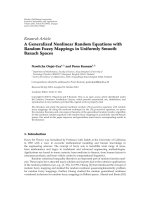
2. SYSTEM MODEL
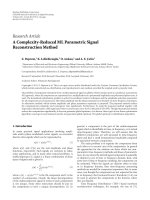
Figure 1 shows the cooperative relaying system under con-
sideration with T single-antenna sources, a T-antenna desti-
nation, and a T-antenna relay to assist the communication
between the sources and destination. For simplicity, we
consider the number of sources equal to that of antennas at
the destination and the relay. However, it is straightforward
to extend to the general case with F single-antenna sources,
a destination with U antennas, and a relay with K antennas
where U, K
≥F as in [15]. In addition, we do not consider the
cooperation between sources (i.e., similar to [15]), although
this cooperation can improve the system performance.
All terminals operate in a half-duplex mode as follows.
Each source S
t
, t ∈{1, , T} takes turn to transmit
its signal in its assigned time slot as shown in Tab le 1.
Throughout this paper, equal-length time slots are assumed.
Its information bit segment I
t
is first encoded and then
mapped into modulation signaling elements s
t
(e.g., M-PSK,
M-QAM) to be transmitted, that is,
s
t
=
s
t
[1], , s
t
[l], , s
t
L
t
=
ϕ
Φ
I
t
,(1)
where ϕ
{·} and Φ{·} represent the modulation and encod-
ing functions, respectively; s
t
[l] is a complex symbol trans-
mitted from the source S
t
at the time instant l (l = 1, , L
t
);
L
t
is the number of modulated symbols in the time slot t.If
all sources use the same modulation channel coding schemes,
L
t
= L for any t ∈{1, , T}.
S
1
S
T
11
T
R
T
1
T
D
Figure 1: System model.
Table 1: Half-duplex transmission mode.
Time slot 1 ··· TT+1
Terminal S
1
··· S
T
R
During the first T time slots , the relay decodes the signals
received from T sources. Subsequently, the relay processes
only the successfully decoded signals (e.g., indicated by the
cyclic redundancy check (CRC)) and forwards the processed
signals to the destination in the time slot (T +1)asshown
in Tab le 1 . The destination uses both the signals directly
received from the sources and the signal from the relay to
perform the signal detection.
With only one additional time slot (T +1)required
to relay all decoded signals of T sources, the bandwidth
efficiency of the proposed schemes is reduced by a factor of
T/(T + 1) as compared to 1/2 for the conventional schemes
in [2–14]. For large T, T/(T + 1) approaches 1, that is, the
bandwidth loss for relaying is negligible. In a synchronized
system with T-antenna relay and destination, simultaneous
transmission from T single-antenna sources in one time slot
is possible for further improved bandwidth efficiency at the
expense of receiver complexity and possible performance
degradation at relay and destination, and beyond the scope
of this paper.
We assume all channels experience independent block
frequency-flat fading, that is, frequency-flat fade is fixed
during a time slot but independently changed from one time
slot to another. Furthermore, channel state information is
available only at the receivers, not at the transmitters.
3. PROPOSED COOPERATIVE RELAYING SCHEMES
In this section, we will discuss the signal processing at the
relay for detection and retransmission.
3.1. Signal detection at relay
Figure 2 shows the simplified receiver structure at the
relay. The baseband-equivalent, discrete-time received signal
vector r
t
[l] at the relay can be expressed as
r
t
[l] = a
t
s
t
[l]+n
t
[l], (2)
K. Ho-Van and T. Le-Ngoc 3
Received signal
MRC
Demapping
Decoder I
t
r
t
[l]
r
t
[l]
Λ(b
t,l,p
|r
t
[l])
Bit metrics calculation
Figure 2: Decoding the signal of the source S
t
at the relay.
where a
t
is the T × 1 channel vector from the transmit
antenna of the source S
t
to the T receive antennas of the relay
(each element of a
t
is modeled as circularly symmetric zero-
mean complex Gaussian random variable), and n
t
[l] is the T
× 1 noise vector with the covariance matrix N
0
I
T×T
(i.e., the
elements of n
t
[l] are modeled as circularly symmetric zero-
mean complex Gaussian random variables with variance
N
0
/2 per dimension). Here, I
T×T
is the unity matrix of the
size T
× T.
To p r o d u c e I
t
, at first maximum ratio combining is
applied to the elements of r
t
[l]as
r
t
[l] =
a
H
t
r
t
[l]
a
H
t
a
t
= a
t
s
t
[l]+n
t
[l], (3)
where a
t
=
a
H
t
a
t
, n
t
[l] is the noise variable with variance
N
0
,and(·)
H
is the complex conjugate transpose.
The resulting signals r
t
[l] are then soft demapped to
produce the log-likelihood ratios (LLRs) for all the coded
bits, that is, the bit metrics, as follows
Λ
b
t,l,p
| r
t
[l]
=
log
s
x
∈χ
1,p
exp
−
r
t
[l] −a
t
s
x
2
/N
0
s
x
∈χ
0,p
exp
−
r
t
[l] −a
t
s
x
2
/N
0
,
(4)
where p
∈{1, 2, , m = log
2
M}, b
t,l,p
is the pth coded bit
in a group of m
= log
2
M bits carried by s
t
[l], and M is the
constellation size. The subsets χ
1,p
and χ
0,p
contain the signal
points in the M-ary constellation whose pth labeling bits are
“1” and “0,” respectively.
Finally, the bit metrics are applied to decoding I
t
(e.g.,
[16]) and error detection (e.g., using CRC) is performed.
3.2. Signal retransmission at relay
For unsuccessful error detection, the corresponding I
t
is dis-
regarded. The successfully recovered I
t
is first interleaved by a
random interleaver Π and then processed for retransmission.
For low implementation complexity, the relay applies the
same channel coding and modulation schemes used by the
sources.
We propose two following retransmission techniques.
3.2.1. Parallel transmission (PT)
For parallel transmission (PT), the N (
≤T) successfully
recovered information segments, I
t
, t ∈{1, , T} are pro-
cessed separately and retransmitted on different antennas as
shown in Figure 3. The relay randomly chooses N among T
transmit antennas (e.g., the first N out of T antennas as in the
simulations). With channel knowledge at relay transmitter,
T
1
Encoder
Mapping
Encoder
Mapping
I
l
I
T
x
T
x
1
Π
Π
Figure 3: Parallel transmission.
an optimum choice of N antennas for retransmission can be
derived. For notational simplicity, we assume T
= N in the
sequel. Obviously, by simply changing the sizes of vectors and
matrices in equations, we easily obtain equations for the case
of T
≥ N.
The signal x
t
transmitted on the antenna t can be
represented as
x
t
=
x
t
[1], , x
t
[l], , x
t
[L]
=
ϕ
Φ
Π
I
t
,(5)
where Π
{·} represents the interleaving function, and x
t
[l]is
the modulated symbol transmitted on the antenna t at the
time instant l.
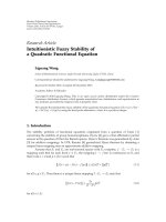
3.2.2. Multiplexing transmission (MT)
Figure 4 shows the block diagram of the proposed mul-
tiplexing transmission (MT) technique. The interleaved
information segments Π
{I
t
} are first bit-level multiplexed as
in [17], that is, the information bits of Π
{I
1
}, , Π{I
T
} are
alternately selected. Therefore, the correlation between I
t
is
introduced to facilitate the high-performance multiuser j oint
iterative decoding (MUJID) to be done at the destination.
While multiplexing increases the volumes (in bits), it also
makes longer parity segments, and hence stronger codes.
Then, the multiplexed segment J
= Ω{Π{I
1
}, , Π{I
T
}} is
encoded, where Ω
{·, ·}represents the multiplexing function.
Finally, the resulting coded bits Φ
{J} are subsequently split
into T parallel streams; each is modulated and transmitted
on one antenna.
4. SIGNAL PROCESSING AT DESTINATION
The destination processes the signals from T sources received
in the first T time slots to produce their corresponding bit
metrics in a similar manner as the relay. Hence, we use the
same notations as in Section 3.1 to avoid the duplication. For
example, Λ(b
t,l,p
| r
t
[l]) is the LLR of the pth coded bit in a
group of m bits carried by s
t
[l], which is computed based on
the signal at the destination received from S
t
.
4 EURASIP Journal on Advances in Signal Processing
T
1
I
l
I
T
x
T
x
1
Π
Π
Encoder
Mapping
Mapping
S/P
M
U
X
Figure 4: Multiplexing transmission.
In the last (T + 1)th time slot, the destination receives the
signal from the relay. The baseband-equivalent, discrete-time
received signal vector y[l] at the time instant l in the time slot
(T + 1) at the destination can be modeled as
y[l]
= Hx[l]+n[l], l = 1, , L,(6)
where y[l] is the T
× 1 received signal vector on the T
receive antennas of the destination, H is the T
× T channel
matrix from the T transmit antennas of the relay to the
T receive antennas of the destination (the elements of H
are modeled as circularly symmetric zero-mean complex
Gaussian random variables), x[l]
= (x
1
[l], x
2
[l], , x
T
[l])
T
is the T × 1 symbol vector transmitted from the relay at
the time instant l,andn[l] is the T
× 1 noise vector with
the covariance matrix N
0
I
T×T
.Here(·)
T
is the transpose
operator.
In the following subsections, we will discuss the proposed
bit metric calculations and iterative decoding structures.
4.1. Bit metric calculations in time slot (T +1)
The destination also needs to calculate the bit metrics for all
coded bits (retransmitted by the relay) in order to perform
the iterative decoding for all T source signals. We consider
three calculation techniques based on maximum likelihood
(ML), zero-forcing (ZF), and QR decomposition.
4.1.1. ML-based bit metric calculation (MLC)
The LLRs for all coded bits transmitted from the relay are
computed as
Λ
b
r,t,l,p
| y[l]
=
log
x∈χ
1,t,p
exp
−
y[l] −Hx
2
/N
0
x∈χ
0,t,p
exp
−
y[l] −Hx
2
/N
0
,
(7)
where p
∈{1,2, , m}, b
r,t,l,p
is the pth coded bit in a
group of m bits carried by x
t
[l]. The subsets χ
1,t,p
and χ
0,t,p
contain the symbol vectors x =(x
1
, x
2
, , x
T
)
T
so that the
signal points x
t
in the M-ary constellation whose pth labeling
bits are “1” and “0,” respectively.
The ML-based bit metric calculationis optimum in
the sense of minimum bit error probability. However, to
calculate Λ(b
r,t,l,p
| y[l]) in (7), we need to sum over 2
mT−1
possible symbol vectors in the set χ
1,t,p
. So, the complexity of
the ML-based bit metrics calculation can be prohibitive for
large M and T. This problem can be remedied by applying the
list slab-sphere detection method in [18], but the searching
range of this method depends on the received signals, thus
making the complexity still high. In this paper, we propose
two low-complexity methods: ZF-based bit metric calculation
(ZFC) and QR -based bit metric calculation (QRC).
4.1.2. ZF-based bit metric calculation (ZFC)
The received vector y[l] is first multiplied by W
=
(H
H
H)
−1
H
H
to suppress the interference between transmit-
ted symbols on different transmit antennas:
z[l]
= Wy [l] = x[l]+η[l], (8)
where z[l]
= (z
1
[l], , z
T
[l])
T
and η[l] = Wn[l] = (η
1
[l],
, η
T
[l])
T
with η
t
[l] being a circularly symmetric zero-
mean complex Gaussian random variable with variance σ
t
[l]
= W(t,:)W(t,:)
H
N
0
. W(t,:) denotes the tth row of the matrix
W.
Explicitly, (8)canberewrittenas
z
t
[l] = x
t
[l]+η
t
[l]. (9)
Therefore, we apply (4) to compute the LLRs for all coded
bits from the relay as
Λ
b
r,t,l,p
| z
t
[l]
=log
s
x
∈χ
1,p
exp
−
z
t
[l]−s
x
2
/σ
t
[l]
s
x
∈χ
0,p
exp
−
z
t
[l]−s
x
2
/σ
t
[l]
.
(10)
Although the ZF-based bit metrics calculation is much
simpler than the ML-based bit metrics calculation (i.e., to
calculate Λ(b
r,t,l,p
| z
t
[l]) in (10), we only need to sum
over 2
m−1
possible symbols in the set χ
1,p
), multiplying
y[l]byW causes the noise enhancement with a factor of
W(t,:)W(t,:)
H
and therefore, leading to the performance
degradation.
4.1.3. QR-based bit-metric calculation (QRC)
Using QR decomposition [19], that is, H
= QR where Q is
a unitary matrix and R
= [r
i,j
] is an upper triangular matrix
(i.e., r
i,j
= 0ifi > j), (6)canberewrittenas
k[l]
= Q
H
y[l] = Rx[l]+ν[l], (11)
where k[l]
= (k
1
[l], , k
T
[l])
T
and ν[l] = Q
H
n[l] = (ν
1
[l],
, ν
T
[l])
T
has the same probability distribution of n[l] since
Q is a unitary matrix. The elements of k[l] can be expressed
as
k
T
[l] = r
T,T
x
T
[l]+ν
T
[l], (12)
k
t
[l] = r
t,t
x
t
[l]+
T
j=t+1
r
t, j
x
j
[l]+ν
t
[l], t = T −1, ,1.
(13)
The above expressions, (12)-(13), indicate that the signal
element x
T
[l] does not contain any interference from the
K. Ho-Van and T. Le-Ngoc 5
other elements, and the element x
t
[l] contains interference
from only the elements x
t+ j
[l], where j = 1, ,(T − t)
and t
= T − 1, ,1. Consequently, we propose the bit
metrics calculation in accompany with the successive soft
interference cancellation (e.g., [20, 21]) as follows.
Basedon(12), and similar to (4), the LLRs for the coded
bits transmitted on the antenna T of the relay can be first
computed as
Λ
b
r,T,l,p
| k
T
[l]
=
log
s
x
∈χ
1,p
exp
−
k
T
[l] −r
T,T
[l]s
x
2
/N
0
s
x
∈χ
0,p
exp
−
k
T
[l] −r
T,T
[l]s
x
2
/N
0
.
(14)
Then, Λ(b
r,T,l,p
| k
T
[l])’s are used to compute the soft
symbols, m
T
[l]’s, corresponding to x
T
[l]’s for the transmit
antenna T and the variances, λ
T
[l]’s, of these soft symbols as
m
T
[l] = E
x
T
[l]
=
M
c=1
x
c
Pr
x
T
[l] = x
c
,
λ
T
[l] = E
x
c
−m
T
[l]
2
=
M
c=1
x
c
−m
T
[l]
2
Pr
x
T
[l] = x
c
,
(15)
where x
c
for c = 1, , M = 2
m
are the M possible values
of x
T
[l], E{·} is the expectation, and the probability of each
possible value of x
T
[l]isgivenby
Pr
x
T
[l] = x
c
=
m
p=1
Pr
b
r,T,l,p
. (16)
In (16), we assume the statistical independence of each
bit b
r,T,l,p
carried by the symbol x
T
[l] and the probability of
b
r,T,l,p
is
Pr
b
r,T,l,p
=
1
1+exp
(−1)
b
r,T,l,p
Λ
b
r,T,l,p
| k
T
[l]
. (17)
Finally, we calculate the LLRs for the coded bits on the
remaining transmit antennas in the order t
= T − 1, ,1in
two steps. In the first step, all interferences from the symbols
x
j
[l]’s, on other transmit antennas j, j = t +1, , T on the
symbol x
t
[l], on the considered transmit antenna t (see (13)),
are softly cancelled out from k
t
[l]as
k
t
[l] = k
t
[l] −
T
j=t+1
r
t, j
m
j
[l]
= r
t,t
x
t
[l]+
T
j=t+1
r
t, j
x
j
[l] −m
j
[l]
+ ν
t
[l]
ν
t
[l]
.
(18)
Based on (18) and the Gaussian assumption on the
residual interference (same as [20]), the ν
t
[l]in(18) is the
circularly symmetric zero-mean complex Gaussian random
variable with variance σ
t
[l]
σ
t
[l] =
T
j=t+1
r
t, j
2
λ
j
[l]+N
0
. (19)
Π
−1
L
(j)
1,e
Π
−1
L
(j)
T,e
De-MUX
L
(j)
e
SISO
P/S
Λ
b
r,t,l,p
Bit metrics
calculation
From
the
relay
MUX
L
(j−1)
a
ΠΠ
SISO
L
(j−1)
1,a
SISO
Bit metrics
calculation
Bit metrics
calculation
From S
1
From S
T
Λ
b
1,l,p
Λ
b
T,l,p
L
(j)
1,e
L
(j)
T,e
L
(j−1)
T,a
Figure 5: Multiuser joint iterative decoding for multiplexing
transmission at the relay.
In (18)and(19), m
j
[l]andλ
j
[l]aregivenby(15),
respectively, with T being substituted by j.
In the second step, we compute the LLRs for the coded
bits transmitted on the transmit antenna t of the relay as
Λ
b
r,t,l,p
| k
t
[l]
=
log
s
x
∈χ
1,p
exp
−
k
t
[l] −r
t,t
[l]s
x
2
/σ
t
[l]
s
x
∈χ
0,p
exp
−
k
t
[l] −r
t,t
[l]s
x
2
/σ
t
[l]
.
(20)
From (14)and(20), we realize that to calculate the LLRs
for the coded bits we only need to sum over 2
m−1
possible
symbols in the set χ
1,p
. Therefore, the searching range of QRC
and ZFC is the same. However, QRC can avoid the noise
enhancement of ZFC (see (18)).
4.2. Iterative decoding
Depending on the transmission techniques at the relay
(parallel or multiplexing), we apply the corresponding
iterative decoding techniques. For notational convenience,
we simplify Λ(b
t,l,p
| r
t
[l]) in (4)asΛ(b
t,l,p
), and unify
Λ(b
r,t,l,p
| y[l]) in (7), Λ(b
r,t,l,p
| z
t
[l]) in (10), Λ(b
r,T,l,p
|
k
T
[l]) in (14), and Λ(b
r,t,l,p
| k
t
[l]) in (20)asΛ(b
r,t,l,p
).
4.2.1. Multiuser joint iterative decoding (MUJID)
Figure 5 shows the decoding diagram for the multiplex-
ing transmission at the relay. Owing to multiplexing the
information bit segments of T sources, the MUJID is
exploited. The decoder considers a sequence of (T + 1) LLR
segments, Λ(b
t,l,p
), Ψ{Λ(b
r,1,l,p
), Λ(b
r,2,l,p
), , Λ(b
r,T,l,p
)}
where Ψ{·, ·} represents the parallel-to-serial converting
function, for t
∈{1, 2, , T} and uses a component soft-
in soft-out (SISO) decoder in [16]torecoverT information
bit segments I
t
’s, from T sources within J iterations.
6 EURASIP Journal on Advances in Signal Processing
L
(j−1)
t,a
L
(j)
t,e
L
(j)
t,e
Λ
b
r,t,l,p
SISOSISO Π
Π
−1
Bit metrics
calculation
Bit metrics
calculation
From
S
t
Λ
b
t,l,p
From the relay
Figure 6: Single-user iterative decoding for source S
t
.
Table 2: Proposed cooperative relaying schemes.
Scheme Description
PT ZF PT, ZFC, SUID
PT
QR PT, QRC, SUID
PT
ML PT, MLC, SUID
MT
ZF MT, ZFC, MUJID
MT
QR MT, QRC, MUJID
MT
ML MT, MLC, MUJID
In each iteration j for j ∈{1, 2, , J}, based on the
LLR segments, Λ(b
t,l,p
), and the int rinsic segments, L
t,a
(j
−1)
,
the SISO decoder computes the extrinsic segments, L
t,e
(j)
,
corresponding to the information bit segments, I
t
’s, where
L
t,a
(0)
= 0, since no prior information about the coded bits is
available in the first iteration. Then, the extrinsic segments,
L
t,e
(j)
, are interleaved and multiplexed into the intrinsic
segment, L
a
(j
−1)
= Ω{Π{L
1,e
(j)
}, , Π{L
T,e
(j)
}},corres-
ponding to the information bit segment, Ω
{Π{I
1
}, ,
Π
{I
T
}}. Sequentially, the SISO decoder computes the
extrinsic segment, L
e
(j)
, based on the LLR segment,
Ψ
{Λ(b
r,1,l,p
), Λ(b
r,2,l,p
), , Λ(b
r,T,l,p
)}, and the intrinsic seg-
ment, L
a
(j
−1)
. Finally, L
e
(j)
is demultiplexed into Textrinsic
segments, L
t,e
(j)
.
At the end of each iteration j, the SISO decoder will
produce a sequence of Textrinsicsegments, L
t,e
(j)
, which are
the soft outputs corresponding to T information segments of
the T sources, I
t
’s. They are stored to be used as inputs of the
SISO decoder in the next iteration (j +1).Afterasufficient
number of iterations, Textrinsicsegments, L
t,e
(j)
,canbe
used to make a decision on the transmitted information bit
segments.
4.2.2. Single-user iterative decoding (SUID)
As the parallel transmission does not introduce any correla-
tion among the T source signals, the SUID can be used to
recover the information bit segment of the source t as shown
in Figure 6. This iterative decoding is akin to the standard
Turbo decoding and, hence, will not be described further in
detail for briefness.
00.51 1.52 2.533.544.55
SNR (dB)
10
0
10
−1
10
−2
10
−3
10
−4
10
−5
BER
DT
Reference [9]
PT
ZF
PT
QR
PT
ML
MT
ZF
MT
QR
MT
ML
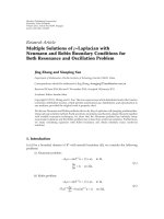
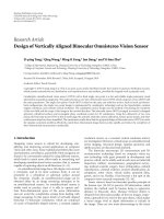
Figure 7: BER versus SNR (SNR
in
= SNR + 10 dB, SNR
rd
= SNR +
5dB).
5. SIMULATION RESULTS
Simulation is used to evaluate and compare the performance
of the proposed schemes and others in an independent
frequency-flat block Rayleigh fading environment under
various conditions.
5.1. Simulation setup
Ta ble 2 summarizes the 6 proposed schemes under consider-
ation by simulation, as the results of 2 relay retransmission
techniques are PT and MT, and 3 bit metric calculations:
MLC, ZFC, and QRC.
As reference, we consider the direct transmission (i.e.,
without the relay) using the 4-state, rate 1/2 recursive sys-
tematic convolutional code (RSCC) of generator polynomial
[1, 5/7] in octal form, and the cooperative relaying scheme
in [9]whereT single-antenna relays help T single-antenna
sources in the pairwise manner. All considered schemes use
the same encoder.
Obviously, the difference in the system model between
our proposed schemes and the scheme in [9] is the way
to deploy T relay antennas: T colocated antennas as in
our system model or T distributed antennas as in [9].
Using T colocated antennas as in our system model benefits
from the high cooperation probability between the sources
and the relay which is essential to provide spatial diversity
at the destination and high bandwidth efficiency (reduced
by a factor of T/(T +1)comparedto1/2for[9]). On
the other hand, the proposed schemes suffer the symbol
interference in the time slot (T + 1) while that in [9]does
not. However, the low bandwidth efficiency of the scheme in
[9] requires an increase in modulation level, thus degrading
K. Ho-Van and T. Le-Ngoc 7
00.51 1.52 2.533.544.55
SNR (dB)
10
−1
10
−2
10
−3
10
−4
10
−5
BER
DT
Reference [9]
PT
ZF
PT
QR
PT
ML
MT
ZF
MT
QR
MT
ML
Figure 8: BER versus SNR (SNR
in
= SNR + 20 dB, SNR
rd
= SNR +
5dB).
the performance, which cannot be compensated by the
interference-free advantage if the cooperation probability
between the source and the relay is low (i.e., interuser
channel is bad). These aspects will be demonstrated by the
following simulation results.
For the purpose of illustration, we investigate the case of
T
= 3. For a fair comparison in terms of bandwidth efficiency,
the direct transmission, the proposed schemes, and that in
[9] use 8-PSK, 16-QAM, and 64-QAM, respectively. We also
assume equal transmitted power for all terminals and for
the relay antennas (i.e., the total relay transmitted power is
equally shared by its antennas, E
{|x
t
[l]|
2
} = E{|s
t
[l]|
2
}/N).
We assume identically and independently distributed
(iid) frequency-flat fading over any source-relay (or desti-
nation) or relay-destination channel. For the scheme in [9],
we assume that the relay t corresponds to the antenna t of
the relay in our model. We denote the average signal-to-
noise ratio of the channel between the source and the receive
antenna of the relay as SNR
in
, between the source and the
receive antenna of the destination as SNR, and between the
transmit antenna of the relay to the receive antenna of the
destination as SNR
rd
.
The information bit segment is of 180-bit length and
the CRC-16-CCITT code is used to check if the recovered
source’s information segment is error free. In addition, we
examine J
= 5iterations.
Due to the above iid fading assumption, all sources in the
schemes PT
ZF, PT ML, MT ZF, and MT ML have identical
performance. However, PT
QR and MT QR offer different
performances for different sources due to the nature of
the soft interference cancellation. For this, the performance
curves for PT
QR and MT QR in the following results
represent the BER averaged over all sources (i.e., sum of BERs
of all sources divided by the number of sources).
00.51 1.52 2.533.544.55
SNR (dB)
10
0
10
−1
10
−2
10
−3
10
−4
10
−5
BER
Reference [9]-SNR
in
=SNR+10 dB
Reference [9]-SNR
in
=SNR+20 dB
PT
ZF-SNR
in
=SNR+10 dB
PT
ZF-SNR
in
=SNR+20 dB
MT
ZF-SNR
in
=SNR+10 dB
MT
ZF-SNR
in
=SNR+20 dB
PT
ML-SNR
in
=SNR+10 dB
PT
ML-SNR
in
=SNR+20 dB
MT
ML-SNR
in
=SNR+10 dB
MT
ML-SNR
in
=SNR+20 dB
Figure 9: BER versus SNR with different interuser channel qualities
and SNR
rd
= SNR+5dB.
5.2. Simulation results
Figure 7 shows the performance curves of the investigated
schemes with SNR
in
= SNR + 10 dB and SNR
rd
= SNR
+ 5 dB. We observe that all the proposed schemes sig-
nificantly outperform the others. Among the proposed
schemes, those with MUJID (i.e., MT
ML/MT QR/MT ZF)
are considerably better than those with SUID (i.e.,
PT
ML/PT QR/PT ZF) due to the longer codeword gen-
erated from the multiplexing operation. However, the
longer codeword also makes longer decoding latency for
the MUJID. Therefore, performance delay trade-off can be
made for different requirements. In addition, among those
with MUJID (or SUID), MT
ML, MT QR, and MT ZF (or
PT
ML, PT QR, and PT ZF) perform in the descending
order but their complexities are in the reversed order. This
is consistent with the previous discussions. Consequently,
another trade-off between performance and complexity is also
an option for different requirements. Moreover, the scheme
in [9] performs even worse than the direct transmission.
This comes from the fact that the former (due to the
nature of the two time slot cooperative relaying) must use
a higher modulation level than that of the latter for the same
bandwidth efficiency, while the interuser channel is of low
8 EURASIP Journal on Advances in Signal Processing
00.51 1.52 2.533.544.55
SNR (dB)
10
0
10
−1
10
−2
10
−3
10
−4
10
−5
BER
DT
Reference [9]
PT
ZF
PT
QR
PT
ML
MT
ZF
MT
QR
MT
ML
Figure 10: BER versus SNR (SNR
in
= SNR + 10 dB, SNR
rd
= SNR
+15dB).
quality, making the cooperation between the source and the
relay take place less frequently. Therefore, the scheme in [9]
is almost in the direct transmission mode (i.e., the direct
transmission with 64-QAM in [9] is obviously worse than
that with 8-PSK).
Figure 8 shows the performance curves of the inves-
tigated schemes with better quality interuser channels,
SNR
in
= SNR + 20 dB. Since the source-destination channel
qualities are unchanged, the direct transmission has the
same performance as previously shown in Figure 7, while
the performance of the scheme in [9] is drastically improved
with the interuser channel quality. This is because with
the improved interuser channel, the cooperation probability
between the source and the relay increases, thus enhancing
the spatial diversity at the destination. However, it is still
worse than any proposed scheme.
The simulation results in Figures 7 and 8 are combined
in Figure 9 to see the impact of the interuser channel on the
BER performance. It is seen that the proposed schemes are
relatively insensitive to the change of the individual interuser
channel, while the scheme in [9]isgreatlyaffected. This
is obvious since multiple colocated antennas at the relay
increase the spatial diversity of the received signals, providing
an overall highly reliable transmission over the source-relay
channel. As a result, improving an individual source-relay
SNR does not contribute significantly to the performance
of signal detection at the relay. In contrast, the single-
input, single-output source-relay channel in the scheme [9]
makes the transmission reliability over this channel heavily
dependent on its channel quality (or SNR).
Figure 10 illustrates the performance of various schemes
with SNR
rd
= SNR + 15 dB and SNR
in
= SNR + 10 dB. The
00.51 1.52 2.533.544.55
SNR (dB)
10
0
10
−1
10
−2
10
−3
10
−4
10
−5
10
−6
BER
Reference [9]-SNR
rd
=SNR+5 dB
Reference [9]-SNR
rd
=SNR+15 dB
PT
ZF-SNR
rd
=SNR+5 dB
PT
ZF-SNR
rd
=SNR+15 dB
MT
ZF-SNR
rd
=SNR+5 dB
MT
ZF-SNR
rd
=SNR+15 dB
PT
ML-SNR
rd
=SNR+5 dB
PT
ML-SNR
rd
=SNR+15 dB
MT
ML-SNR
rd
=SNR+5 dB
MT
ML-SNR
rd
=SNR+15 dB
Figure 11: BER versus SNR with different relay destination channel
qualities, SNR
in
= SNR+10dB.
00.51 1.52 2.533.544.55
SNR (dB)
10
−1
10
−2
10
−3
10
−4
10
−5
10
−6
BER
DT
Reference [9]
PT
ZF
PT
QR
PT
ML
MT
ZF
MT
QR
MT
ML
Figure 12: BER versus SNR (SNR
in
= SNR + 20 dB, SNR
rd
= SNR
+15dB).
K. Ho-Van and T. Le-Ngoc 9
0123456789
SNR (dB)
10
−1
10
−2
10
−3
10
−4
BER
10
−1
10
−2
10
−3
10
−4
BER
012345678
SNR (dB)
(a) PT
ZF (d) MT ZF
012345678
SNR (dB)
10
−1
10
−2
10
−3
10
−4
BER
10
−1
10
−2
10
−3
10
−4
10
−5
BER
01234567
SNR (dB)
(b) PT
QR (e) MT QR
01234567
SNR (dB)
10
−1
10
−2
10
−3
10
−4
10
−5
BER
10
−1
10
−2
10
−3
10
−4
10
−5
BER
00.511.522.533.544.55
SNR (dB)
(c) PT
ML (f) MT ML
Iteration 1
Iteration 2
Iteration 3
Iteration 4
Iteration 5
Iteration 1
Iteration 2
Iteration 3
Iteration 4
Iteration 5
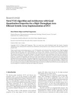
Figure 13: BER versus SNR for different iterations (SNR
in
= SNR + 10 dB and SNR
rd
= SNR+5dB).
performance of the direct transmission is the same as shown
in Figure 7 due to the unchanged source-destination channel
qualities. With the improved relay-destination channel, the
relay forwards the processed information of the sources
more reliably, thus enhancing the spatial diversity at the
destination. For the scheme in [9], its performance is not
improved much, since the cooperation between the relays
and the sources are rare (due to unchanged SNR
in
=
SNR + 10 dB as for Figure 7), and as a consequence the
better relay-destination channel does not contribute much
10 EURASIP Journal on Advances in Signal Processing
to its performance improvement. For easy comparison, we
combine the results in Figures 7 and 10 into Figure 11.
Figure 11 indicates that the proposed schemes perform
drastically better with improved relay-destination channel
quality as compared to the others. Figure 11 also shows
that MUJID is significantly better than SUID, but their
performance difference is reduced with the increased SNR
rd
.
For example, at the target BER of 10
−3
, the improvement
offered by MT
ML as compared to PT ML is around 2 dB for
SNR
rd
= SNR + 5 dB and reduced to only 0.75 dB for SNR
rd
= SNR + 15 dB.
To see the effect of both the source-relay channels
and the relay-destination channels on the performance of
the investigated schemes, we consider the case where the
source-relay channels are improved (e.g., SNR
in
= SNR
+ 20 dB), while the relay-destination channels are similar
to those in Figure 10, that is, SNR
rd
= SNR + 15 dB.
The simulation results are illustrated in Figure 12. Since
the source-destination channel qualities are unchanged, the
direct transmission has the same performance as shown in
Figure 7, while the performance of the proposed schemes
and that in [9] are substantially improved. In addition, the
performance gap between the proposed scheme and that in
[9] is dramatically increased with the improvement of the
source-relay channels and the relay-destination channels (by
comparing Figures 7 and 12).
Figure 13 indicates the BER performance of the 6 pro-
posed schemes for different iterations where SNR
in
= SNR +
10 dB and SNR
rd
= SNR + 5 dB. We see that all the proposed
schemes converge after 3 iterations.
6. CONCLUSIONS
We proposed the coded cooperative relaying schemes using a
multiantenna relay to assist the information retransmission
of multiple sources. These schemes achieve high bandwidth
efficiency as well as high performance due to different
transmission techniques at the relay and the diversified
iterative decoding at the destination. In addition, different
from the conventional cooperative relaying schemes (e.g.,
[9]) whose performance heavily depends on the individual
source-relay channel quality, the proposed schemes are
almost insensitive to the individual source-relay channel
due to the diversity provided by multiple receive antennas.
Therefore, the relay can help the sources to improve their
performances in a large range of SNR.
In the proposed schemes, we do not consider the
cooperation between sources. This cooperation is expected to
improve further performance but also makes the cooperative
schemes more complicated. It could be an interesting topic
for further research.
For a fixed relay as considered in this paper, the channel
from the relay and the destination is less time variant.
Consequently, the channel state information can be available
at the relay so that some techniques such as precoding
and power allocation at the relay can be exploited to
enhance the information transmission reliability over the
relay-destination channel, thus improving the overall system
performance.
ACKNOWLEDGMENT
This work was partially supported by the Prompt/NSERC/
CRD Grants with InterDigital Canada.
REFERENCES
[1] A. Nosratinia, T. E. Hunter, and A. Hedayat, “Cooperative
communication in wireless networks,” IEEE Communications
Magazine, vol. 42, no. 10, pp. 74–80, 2004.
[2] R. Pabst, B. H. Walke, D. C. Schultz, et al., “Relay-based
deployment concepts for wireless and mobile broadband
radio,” IEEE Communications Magazine, vol. 42, no. 9, pp. 80–
89, 2004.
[3] J.N.Laneman,D.N.C.Tse,andG.W.Wornell,“Cooperative
diversity in wireless networks: efficient protocols and outage
behavior,” IEEE Transactions on Information Theory, vol. 50,
no. 12, pp. 3062–3080, 2004.
[4] A. Bletsas, A. Khisti, D. P. Reed, and A. Lippman, “A
simple cooperative diversity method based on network path
selection,” IEEE Journal on Selected Areas in Communications,
vol. 24, no. 3, pp. 659–672, 2006.
[5]A.S.Ibrahim,A.K.Sadek,W.Su,andK.J.R.Liu,
“Cooperative communications with partial channel state
information: when to cooperate?” in Proceedings of the IEEE
Global Telecommunications Conference (GLOBECOM ’05), vol.
5, pp. 3068–3072, St. Louis, Mo, USA, November-December
2005.
[6] K. G. Vardhe, D. Reynolds, and M. C. Valenti, “Outage proba-
bility of a multi-user cooperation protocol in an asynchronous
CDMA cellular uplink,” in Proceedings of the 41st Annual
Conference on Information Sciences and Systems (CISS ’07),pp.
179–184, Baltimore, Md, USA, March 2007.
[7] M. C. Valenti and B. Zhao, “Distributed turbo codes: towards
the capacity of the relay channel,” in Proceedings of the 58th
IEEE Vehicular Technology Conference (VTC ’03), vol. 1, pp.
322–326, Orlando, Fla, USA, October 2003.
[8] T. E. Hunter, S. Sanayei, and A. Nosratinia, “Outage analysis of
coded cooperation,” IEEE Transactions on Information Theory,
vol. 52, no. 2, pp. 375–391, 2006.
[9] M. Janani, A. Hedayat, T. E. Hunter, and A. Nosratinia,
“Coded cooperation in wireless communications: space-time
transmission and iterative decoding,” IEEE Transactions on
Signal Processing, vol. 52, no. 2, pp. 362–371, 2004.
[10] H. T. Nguyen, H. H. Nguyen, and T. Le-Ngoc, “A bandwidth-
efficient coded cooperative communications system,” in Pro-
ceedings of the 64th IEEE Vehicular Technology Conference
(VTC ’06), pp. 1–5, Montreal, QC, Canada, September 2006.
[11] H. Ochiai, P. Mitran, and V. Tarokh, “Variable-rate two-
phase collaborative communication protocols for wireless
networks,” IEEE Transactions on Information Theory, vol. 52,
no. 9, pp. 4299–4313, 2006.
[12] A. Adinoyi and H. Yanikomeroglu, “Cooperative relaying in
multi-antenna fixed relay networks,” IEEE Transactions on
Wireless Communications, vol. 6, no. 2, pp. 533–544, 2007.
[13] C. Hausl and P. Dupraz, “Joint network-channel coding
for the multiple-access relay channel,” in Proceedings of
the International Workshop on Wireless Ad Hoc and Sensor
Networks (IWWAN ’06), New York, NY, USA, June 2006.
[14]H.T.Nguyen,H.H.Nguyen,andT.Le-Ngoc,“Ajoint
network-channel coding scheme for relay-based commu-
nications,” in Proceedings of the Canadian Conference on
Electrical and Computer Engineering (CCECE ’07), pp. 904–
907, Vancouver, BC, Canada, April 2007.
K. Ho-Van and T. Le-Ngoc 11
[15] F. A. Onat, H. Yanikomeroglu, and S. Periyalwar, “Relay-
assisted spatial multiplexing in wireless fixed relay networks,”
in Proceedings of the IEEE Global Telecommunications Confer-
ence (GLOBECOM ’06), San Francisco, Calif, USA, November
2006.
[16] S. Benedetto, D. Divsalar, G. Montorsi, and F. Pollara, “A
soft-input soft-output APP module for iterative decoding of
concatenated codes,” IEEE Communications Letters, vol. 1, no.
1, pp. 22–24, 1997.
[17] H V. Khuong and T. Le-Ngoc, “A bandwidth-efficient coded
user-cooperation scheme for flat block fading channels,” in
Proceedings of the 4th Internat ional Symposium on Wireless
Communication Systems (ISWCS ’07), pp. 421–425, Trond-
heim, Norway, October 2007.
[18] K K. Wong, A. Paulraj, and R. D. Murch, “Efficient high-
performance decoding for overload MIMO antenna system,”
IEEE Transactions on Wireless Communications, vol. 6, no. 5,
pp. 1833–1843, 2007.
[19] R. Horn and C. Johnson, Matrix Analysis, Cambridge Univer-
sity Press, Cambridge, UK, 1985.
[20] W J. Choi, K W. Cheong, and J. M. Cioffi,“Iterativesoft
interference cancellation for multiple antenna systems,” in
Proceedings of the IEEE Wireless Communications and Network-
ing Conference (WCNC ’00), vol. 1, pp. 304–309, Chicago, Ill,
USA, September 2000.
[21] Y. Li, X G. Xia, and G. Wang, “Simple iterative methods
to exploit the signal-space diversity,” IEEE Transactions on
Communications, vol. 53, no. 1, pp. 32–38, 2005.