Báo cáo hóa học: " Facile Synthesis of Novel Nanostructured MnO2 Thin Films and Their Application in Supercapacitors" pptx
Bạn đang xem bản rút gọn của tài liệu. Xem và tải ngay bản đầy đủ của tài liệu tại đây (392.87 KB, 6 trang )
NANO EXPRESS
Facile Synthesis of Novel Nanostructured MnO
2
Thin Films
and Their Application in Supercapacitors
H. Xia Æ W. Xiao Æ M. O. Lai Æ L. Lu
Received: 16 April 2009 / Accepted: 14 May 2009 / Published online: 2 June 2009
Ó to the authors 2009
Abstract Nanostructured a-MnO
2
thin films with differ-
ent morphologies are grown on the platinum substrates by a
facile solution method without any assistance of template
or surfactant. Microstructural characterization reveals that
morphology evolution from dandelion-like spheres to
nanoflakes of the as-grown MnO
2
is controlled by synthesis
temperature. The capacitive behavior of the MnO
2
thin
films with different morphologies are studied by cyclic
voltammetry. The a-MnO
2
thin films composed of dande-
lion-like spheres exhibit high specific capacitance, good
rate capability, and excellent long-term cycling stability.
Keywords Supercapacitor Á MnO
2
Á Nanostructure Á
Thin film Á Cyclic voltammetry
Introduction
In recent years, manganese oxides (MnO
2
) have attracted
considerable interests due to their distinctive physical and
chemical properties and wide applications in catalysis, ion
exchange, molecular adsorption, biosensor, and energy
storage [1–5]. Specifically, manganese oxides have been
extensively evaluated as electrode materials for superca-
pacitors due to their low cost and environmental benignity
compared to noble metal oxides such as RuO
2
[6–8]. In the
development of supercapacitors, nanostructured electrode
materials have received great interests as they exhibit
higher specific capacitance and rate capability compared to
traditional bulk materials. Over the years, various nano-
structured manganese oxides, including one-dimensional (1-
D) (nanorodes, nanowires, nanobelts, nanoneedles, and nano-
tubes), two-dimensional (2-D) (nanosheets, nanoflakes), and
three-dimentional (3-D) (nanospheres, nanoflowers, hollow
urchins) nanostructures, have been synthesized [9–16]. 3-D
hierarchical porous structures often produce more active
sites and exhibit more favorable electrochemical properties
than 2-D and 1-D structures. However, facile synthesis and
mass production of complex 3-D nanostructures are still a
challenge in the areas of materials science [17–20]. It has
been reported that a core-shell structure with spherically
aligned nanorods of a-MnO
2
can be prepared through a
simple room temperature reaction between MnSO
4
and
(NH
4
)
2
S
2
O
8
with a catalyst of Ag
?
in an acid solution [21].
A similar method used by Gong et al. is able to synthesize
MnO
2
hollow urchins with a reactive template of carbon
spheres [22]. Wang et al. also reported the synthesis of
hierarchical a-MnO
2
spheres by the reaction between
MnSO
4
and K
2
S
2
O
8
with the addition of CuSO
4
in an acidic
solution [23]. However, the preparation of 3-D nanostruc-
tured MnO
2
in the thin film form has never been reported.
Since the use of composite electrodes introduces additional
undesirable interfaces in the electrode material with the risk
of negating the benefits of electrochemistry using nano-
structures, thin film electrodes enable us to investigate the
electrochemical properties of the active material itself
without the influence of binders and conductive additives as
required for composite electrodes.
In this paper, we propose the stratagem to synthesize
3-D a-MnO
2
dandelion-like spheres and 2-D a-MnO
2
nanoflakes by a reaction between MnSO
4
and (NH
4
)
2
S
2
O
8
in a Na
2
SO
4
solution at low temperatures. With a platinum
(Pt) substrate submerged into the reaction solution, the
nanostructured MnO
2
can be directly deposited on the Pt
H. Xia Á W. Xiao Á M. O. Lai Á L. Lu (&)
Department of Mechanical Engineering, National University of
Singapore, 9 Engineering Drive 1, Singapore 117576, Singapore
e-mail:
123
Nanoscale Res Lett (2009) 4:1035–1040
DOI 10.1007/s11671-009-9352-4
substrate in the thin film form. The effects of the synthesis
temperature on the morphology of the films are investi-
gated, and the capacitive behaviors of nanostructured
MnO
2
thin films with different morphologies are studied
and compared.
Experimental
Synthesis of Nanostructured MnO
2
Analytical grade MnSO
4
, (NH
4
)
2
S
2
O
8
, and Na
2
SO
4
from
Sigma–Aldrich were used. A typical synthesis of nano-
structured MnO
2
was performed by dissolving MnSO
4
,
(NH
4
)
2
S
2
O
8
, and Na
2
SO
4
with a molar ratio of 1:1:1 in
30 mL deionized water at room temperature. The con-
centrations of Mn
2?
,S
2
O
8
2-
, and SO
4
2-
in the solution
are the same as 0.1 mol L
-1
. A Pt substrate was sub-
merged into the solution, while the solution was mag-
netically stirred in a beaker at room temperature (RT) for
12 h or at 80 °C for 2 h. One side of the Pt substrate
was covered with Parafilm, so that MnO
2
can only be
deposited on one side. After the reaction, the Pt substrate
was washed using distilled water and then dried in the
vacuum at 60 °C overnight.
Characterization
Structure and crystallinity of thin films were characterized
using a Shimadzu XRD-6000 X-ray diffractometer with Cu
Ka radiation at a scanning rate of 1°min
-1
. Surface mor-
phology of the as-deposited thin films was characterized
using a Hitachi S-4100 field emission scanning electron
microscope (FESEM). Weights of the MnO
2
thin films
were measured using a microbalance with an accuracy of
0.01 mg.
All electrochemical measurements were conducted
using a Solartron 1287 electrochemical interface com-
bined with a Solatron 1260 frequency response analyzer.
For the electrochemical measurements, a three-electrode
cell system composed of a MnO
2
thin film electrode as
the working electrode, a high surface carbon rod as the
counter electrode, and an Ag/AgCl reference electrode
was employed. The capacitive behaviors of the as-
deposited MnO
2
thin films were characterized by cyclic
voltammetry (CV) in 1 M Na
2
SO
4
electrolyte at room
temperature. CV measurements were performed on the
three-electrode cells in the voltage window between 0
and 0.9 V at different scan rates from 20 to 200 mV s
-1
.
Electrochemical impedance spectra (EIS) of different
thin film electrodes were measured at the open-circuit
potential in the frequency range from 100 kHz to
10 mHz.
Results and Discussion
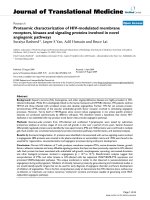
Figure 1a, b shows the XRD patterns of the MnO
2
thin
films synthesized at different temperatures. Notably, major
diffraction peaks in Fig. 1a, b can be indexed as a tetrag-
onal symmetry of a-MnO
2
with a space group of I4/m
(JCPDS Card, No. 44-0141). Comparing Fig. 1a with
Fig. 1b, it can be seen that the diffraction peaks in Fig. 1a
are sharper and stronger, indicating that the degree of
crystallinity of the products is enhanced as the synthesis
temperature increases. However, some small impurity
peaks observed from both Fig. 1a, b can be indexed as
Mn
3
O
4
, which is probably due to the incomplete oxidation
reaction between Mn
2?
and S
2
O
8
2-
. The complete for-
mation of MnO
2
from the solution can be expressed as the
following reaction:
MnSO
4
þðNH
4
Þ
2
S
2
O
8
þ 2H
2
O
! MnO
2
þðNH
4
Þ
2
SO
4
þ 2H
2
SO
4
ð1Þ
a-MnO
2
has usually been found to be the product of the
oxidation of Mn
2?
by S
2
O
8
2-
either through a
hydrothermal reaction [24] or through a mild solution
reaction [21–23]. It has been observed in this study that the
formation of nanostructured MnO
2
is preferred to deposit
on the Pt substrate rather than in the solution. Therefore,
the preparation of MnO
2
thin films (as shown in Fig. 1c) in
this study is quite simple and convenient compared with
electrochemical deposition, which is usually employed to
prepare MnO
2
thin films.
The morphologies of the MnO
2
thin films synthesized at
different temperatures are shown in Fig. 2. It can be seen
from Fig. 2a that the film synthesized at RT is composed of
uniform microscopic spheres with diameters ranging from
0.5 to 1 lm. The magnified FESEM image (Fig. 2b) shows
that these microscopic spheres are composed of
Fig. 1 a XRD pattern of the MnO
2
thin film synthesized at RT, b
XRD pattern of the MnO
2
thin film synthesized at 80 °C (The dotted
lines in red color represent the diffraction peaks from Mn
3
O
4
), and c
photos of the Pt substrate before and after the deposition
1036 Nanoscale Res Lett (2009) 4:1035–1040
123
nanowhiskers, resulting in a dandelion-like morphology. Li
et al. [22] reported that a core-shell structure microspheres
(2–3 lm) of a-MnO
2
can be obtained by the reaction
between MnSO
4
and (NH
4
)
2
S
2
O
8
with the addition of
AgNO
3
catalyst at RT for 1–2 days. The thin shell of this
structure is composed of nanorods, and this morphology
can only be obtained with the existence of Ag
?
. Wang
et al. [23] reported that sea urchin-shaped microspheres
(*1 lm) of a-MnO
2
can be obtained by the reaction
between MnSO
4
and K
2
S
2
O
8
with the addition of CuSO
4
at
70 °C for 3 days. In the present work, the 3-D hierarchical
structure of a-MnO
2
can be obtained at RT in a relatively
short synthesis time (12 h) without using any AgNO
3
or
CuSO
4
since the addition of catalyst of AgNO
3
or CuSO
4
may induce Ag
?
or Cu
2?
impurities in the final MnO
2
products [23]. It is assumed that reaction between Mn
2?
and S
2
O
8
2-
in the Na
2
SO
4
solution with a Pt substrate is
relatively faster compared to the previous studies [22, 23].
It is interesting to observe a morphology evolution of the
film, as the synthesis temperature increases. As shown in
Fig. 2d, the film synthesized at 80 °C exhibits another type
of porous structure with nanoflakes almost vertically
aligned on the Pt substrate. The magnified FESEM image
(Fig. 2e) shows that the average size of the nanoflakes is
about 500 nm, and the thickness of the nanoflakes is less
than 50 nm.
The possible formation mechanism for the hierarchical
MnO
2
spheres is schematically illustrated in Fig. 2c.
Generally speaking, the crystal growth process always
includes two steps: the initial nucleation stage and fol-
lowing crystal growth stage [25, 26]. Initially, MnO
2
col-
loids are slowly formed and attached to the Pt substrate.
After which, the absorbed MnO
2
colloids on the Pt sub-
strate tend to aggregate loosely to form spherical appear-
ance due to their high surface energies. Because the
reaction temperature is at RT, Gibbs energy for nucleation
of new MnO
2
sites is low. As a consequence, MnO
2
col-
loids tend to attach on the habit planes of existing MnO
2
sites, leading to the formation of 1-D nanowhiskers from
the initial colloidal microspheres. With increase in the
processing duration, finally dandelion-like 3-D micro-
spheres of MnO
2
on the Pt substrate appear. However, on
the contrary to Wang’s finding [23], the increase in reac-
tion temperature in this study is unable to improve the
formation of 3-D hierarchical microspheres of MnO
2
but
leads to the formation of 2-D nanoflakes. This phenomenon
can be explained by the change in growth mechanisms as
shown in Fig. 2f. When the reaction temperature is
Fig. 2 FESEM images for RT
synthesized MnO
2
: a low
magnification and b high
magnification, c schematic
illustration for the possible
formation mechanism of
dandelion-like MnO
2
microspheres, FESEM images
for 80 °C synthesized MnO
2
: d
low magnification and e high
magnification, and f schematic
illustration for the possible
formation mechanism of MnO
2
nanoflakes
Nanoscale Res Lett (2009) 4:1035–1040 1037
123
increased to 80 °C, the reaction rate is greatly enhanced
along with the high rate of adsorption of MnO
2
colloids to
the Pt substrate. Under such circumstances, in addition to
the one-dimentional growth of the nuclei along the low
energy direction [27], the growth of the nuclei along other
directions can also happen due to the fast nucleation and
adsorption rates of MnO
2
at an elevated temperature.
Therefore, nanoflakes instead of nanowhiskers form
resulting in the morphology evolution.
The 3-D and 2-D nanostructured MnO
2
are promising as
electrode materials for supercapacitors due to their porous
structure, large surface area, and short diffusion length for
protons or alkali cations. In order to evaluate the electro-
chemical properties of the as-deposited thin films, the thin
film samples with different nanostructures were charac-
terized in aqueous 0.1 M Na
2
SO
4
electrolyte with CV
measurements. The CV curves at various scan rates from
20 to 200 mV s
-1
for the sample A and B are shown in
Fig. 3a, b (sample A represents MnO
2
with dandelion-like
sphere morphology, and sample B represents MnO
2
nanoflakes). It can be seen that the curves at the low scan
rate of 20 mV s
-1
for both samples exhibit ideal sym-
metrical rectangle-like shape indicating ideal capacitive
behavior. As the scan rate increases, slight distortion from
the ideal symmetrical rectangle shape can be observed
from the CV curves for both samples. However, it is clear
to see that the distortion from the rectangularity of the CV
curves for the sample A is much less than that for the
sample B, indicating much better rate performance of the
sample A due to its finer nano-architecture. The specific
capacitance of the nanostructured MnO
2
film can be
obtained by the following equation:
CðF=gÞ¼
Q
DE Á m
ð2Þ
where Q is the voltammetric charge, DE is the voltage
window (0.9 V), and m is the mass of the active material of
the electrode. The specific capacitances at different scan
rates for both samples are shown in Fig. 3c. At the scan
rate 20 mV s
-1
, the sample A exhibits a much higher
specific capacitance of about 230 F/g than 180 F/g of the
sample B. As the scan rate increases, the specific capaci-
tance for both samples decreases, which is typical for
electrochemically active MnO
2
materials. At the highest
scan rate of 200 mV s
-1
, the sample A can maintain 66%
of its full capacitance (we set the specific capacitance at
20 mV s
-1
as the full capacitance) while the sample B can
only maintain 55% of its full capacitance, indicating that
the sample A has much better rate capability than that of
the sample B. Figure 3d compares the Nyquist plots for the
MnO
2
thin films with different nanostructures. A depressed
semicircle in the high-frequency range corresponding to
the charge-transfer resistance, and a straight sloping line in
the low-frequency range corresponding to the diffusive
resistance can be observed for both samples. As shown in
Fig. 3d, it is clear that the sample A has lower charge-
Fig. 3 a The CV curves at
various scan rates from 20 to
200 mV s
-1
for the MnO
2
film
synthesized at RT, b the CV
curves at various scan rates
from 20 to 200 mV s
-1
for the
MnO
2
film synthesized at
80 °C, c specific capacitance at
various scan rates for the MnO
2
thin films with different
nanostructures, and d EIS
spectra of MnO
2
thin films with
different nanostructures
1038 Nanoscale Res Lett (2009) 4:1035–1040
123
transfer resistance and diffusive resistance compared with
those of the sample B, confirming the superior capacitive
behavior of the sample A. Based on the previous paper by
Chou et al. [28], surface area of thin film can be derived
from the double layer capacitance by fitting EIS using
equivalent circuit. The calculated surface areas of the
sample A and the sample B are about 414 and 125 m
2
g
-1
respectively. Pseudocapacitance of MnO
2
mainly origi-
nates from the adsorption of cations in the electrolyte
(M
?
= Li
?
,Na
?
, and K
?
) on the surface of MnO
2
and
also possible intercalation/deintercalation of H
?
and alka-
line metal cations in the bulk of MnO
2
[29]. Since the 3-D
dandelion-like microspheres of the sample A are composed
of much finer nanowhiskers with very small size, they
provide a much larger surface area per gram and shorter
diffusion length for cations, comparing to the relatively
large 2-D nanoflakes of the sample B. Therefore, the
morphology advantage of sample A explains why it can
exhibit a higher specific capacitance and better rate capa-
bility than those of the sample B.
The sample A, showing better capacitive behavior in
rate capability test, was further investigated for long-term
cycling stability. The CV curves at different cycling stages
and variation of specific capacitance over 2,000 cycles are
shown in Fig. 4a, b. As shown in Fig. 4a, the CV curves for
the 1st, 500th, 1000th, and 2000th cycles almost over-
lapped with each other, indicating excellent cycling sta-
bility. After 2,000 cycles, there is no degradation of the
capacitive behavior, indicating no significant structural or
microstructural changes in the MnO
2
thin film electrodes.
The CV curve after 2,000 cycles is noted to become more
symmetrical with the rectangular shape compared with the
first cycle, indicating improved capacitive behavior after
long time cycling. The specific capacitance of the sample A
(as shown in Fig. 4b) slightly decreases for the first 30–
40 cycles then starts to increase very slowly with the
cycling. As shown in the XRD results, there is a small
amount of Mn
3
O
4
exist in the film. Mn with a lower oxi-
dation state in the Mn
3
O
4
is probably oxidized to Mn
4?
during the long time CV cycling, resulting in improved
capacitive behavior and an small increase of specific
capacitance.
Conclusions
MnO
2
thin films with nanostructures have been prepared on
Pt substrates by a facile and mild solution method. The
MnO
2
film prepared at RT with a long reaction time is
composed of dandelion-like microspheres, which consists
of nanowhiskers with very small size. The reaction tem-
perature plays an important role in controlling the surface
morphology of the film. As the reaction temperature was
increased to 80 °C, a film composed of nanoflakes can be
prepared in a very short time. The CV measurements
indicate that MnO
2
thin films prepared by this method are
promising as electrodes for supercapacitors. The film
composed of dandelion-like microspheres exhibited a
higher specific capacitance and better rate capability than
the film composed of nanoflakes, which is probably due to
the high surface area and smaller feature of the micro-
spheres. The excellent cycling stability and good rate
capability of the film composed of dandelion-like micro-
spheres coupled with the simple and low cost synthesis
method make this material attractive for large applications.
Acknowledgments This research is supported by National Uni-
versity of Singapore and Agency for Science, Technology and
Research through the research grant R-265-000-292-305 (072 134
0051).
References
1. Y.S. Ding, X.F. Shen, S. Sithambaram, S. Gomez, R. Kumar,
V.M.B. Crisostomo, S.L. Suib, M. Aindow, Chem. Mater. 17,
5382 (2005). doi:10.1021/cm051294w
Fig. 4 a CV curves for the 1st, 500th, 1,000th, and 2,000th cycles for
the MnO
2
thin film synthesized at RT and b the variation of specific
capacitance with respect to cycle number for the MnO
2
thin film
synthesized at RT
Nanoscale Res Lett (2009) 4:1035–1040 1039
123
2. O. Giraldo, S.L. Brock, W.S. Willis, M. Marquez, S.L. Suib, S.
Ching, J. Am. Chem. Soc. 122, 9330 (2000). doi:10.1021/
ja001860i
3. Y.S. Ding, X.F. Shen, S. Gomez, H. Luo, M. Aindow, S.L. Suib,
Adv. Funct. Mater. 16, 549 (2006). doi:10.1002/adfm.200500436
4. J. Yu, T. Zhao, B. Zeng, Electrochem. Commun. 10, 1318 (2008).
doi:10.1016/j.elecom.2008.06.028
5. V. Subramanian, H.W. Zhu, B.Q. Wei, Electrochem. Commun. 8,
827 (2006). doi:10.1016/j.elecom.2006.02.027
6. S.L. Chou, J.Z. Wang, S.Y. Chew, H.K. Liu, S.X. Dou, Elect-
rochem. Commun. 10, 1724 (2008). doi:10.1016/j.elecom.2008.
08.051
7. K.R. Prasad, N. Miura, Electrochem. Commun. 6, 1004 (2004).
doi:10.1016/j.elecom.2004.07.017
8. M.S. Wu, P.C.J. Chiang, Electrochem. Commun. 8, 383 (2006).
doi:10.1016/j.elecom.2005.12.014
9. H. Xia, W. Xiao, M.O. Lai, L. Lu, Funct. Mater. Lett. 2,13
(2009). doi:10.1142/S1793604709000478
10. X. Wang, Y.D. Li, J. Am. Chem. Soc. 124, 2880 (2002). doi:
10.1021/ja0177105
11. M.S. Wu, J.T. Lee, Y.Y. Wang, C.C. Wan, J. Phys. Chem. B.
108, 16331 (2004). doi:10.1021/jp0404955
12. F.Y. Cheng, J.Z. Zhao, W.N. Song, C.S. Li, H. Ma, J. Chen, P.W.
Shen, Inorg. Chem. 45, 2038 (2006). doi:10.1021/ic051715b
13. R.Z. Ma, Y. Bando, L.Q. Zhang, T. Sasaki, Adv. Mater. 16, 918
(2004). doi:10.1002/adma.200306592
14. N. Wang,Y. Gao, J. Gong, X.Y. Ma, X.L. Zhang, Y.H. Guo, L.Y. Qu,
Eur. J. Inorg. Chem. 2008, 3827 (2008). doi:10.1002/ejic.200800236
15. M.W. Xu, L.B. Kong, W.J. Zhou, H.L. Li, J. Phys. Chem. C. 111,
19141 (2007). doi:10.1021/jp076730b
16. J.P. Ni, W.C. Lu, L.M. Zhang, B.H. Yue, X.F. Shang, Y. Lv, J.
Phys. Chem. C. 113, 54 (2009). doi:10.1021/jp806454r
17. C.L. Yan, D.F. Xue, J. Phys. Chem. B. 110, 1581 (2006). doi:
10.1021/jp056373?
18. C.L. Yan, D.F. Xue, Adv. Mater. 20, 1055 (2008). doi:
10.1002/adma.200701752
19. J. Liu, D.F. Xue, Adv. Mater. 20, 2622 (2008). doi:10.1002/
adma.200800208
20. X. Zhao, X. Ren, C.T. Sun, X. Zhang, Y.F. Si, C.G. Yan, J.S. Xu,
D.F. Xue, Funct. Mater. Lett. 1, 167 (2008). doi:10.1142/
S1793604708000393
21. Z.Q. Li, Y. Ding, Y.J. Xiong, Q. Yang, Y. Xie, Chem. Commun.
(Camb) 918 (2005). doi:10.1039/b414204g
22. B.X. Li, G.X. Rong, Y. Xie, L.F. Huang, C.Q. Feng, Inorg.
Chem. 45
, 6404 (2006). doi:10.1021/ic0606274
23. H.E. Wang, Z.G. Lu, D. Qian, S.P. Fang, J.F. Zhang, J. Alloys
Compd. 466, 250 (2008). doi:10.1016/j.jallcom.2007.11.041
24. V. Subramanian, H.W. Zhu, R. Vajtai, P.M. Ajayan, B.Q. Wei, J.
Phys. Chem. B. 109, 20207 (2005). doi:10.1021/jp0543330
25. J.S. Xu, D.F. Xue, Y.C. Zhu, J. Phys. Chem. B. 110, 17400
(2006). doi:10.1021/jp0632788
26. L. Lu, L.P. Li, X.J. Wang, G.S. Li, J. Phys. Chem. B. 109, 17151
(2005). doi:10.1021/jp052780?
27. C.C. Hu, K.H. Chang, Y.T. Wu, C.Y. Hung, C.C. Lin, Y.T. Tsai,
Electrochem. Commun. 10, 1792 (2008). doi:10.1016/j.elecom.
2008.09.011
28. S.L. Chou, F.Y. Chen, J. Chen, J. Power Sources 162, 727 (2006).
doi:10.1016/j.jpowsour.2006.06.033
29. W.F. Wei, X.W. Cui, W.X. Chen, D.G. Ivey, J. Phys. Chem. C.
112, 15075 (2008). doi:10.1021/jp804044s
1040 Nanoscale Res Lett (2009) 4:1035–1040
123