Sensors, Focus on Tactile, Force and Stress Sensors 2011 Part 11 ppt
Bạn đang xem bản rút gọn của tài liệu. Xem và tải ngay bản đầy đủ của tài liệu tại đây (2.48 MB, 30 trang )
Tactile Sensing for Robotic Applications
291
3. Tactile sensing: why?
What happens if the humans have all sense modalities other than the sense of touch? The
importance of touch/tactile sensing is implicit in this question which can be answered by
performing a simple experiment of exploring the objects after putting hands on an ice block
for a while or by making the hand numb through local anesthesia. In one such experiment,
presented in (Westling & Johannson 1984), the skin on volunteers’ hand was anesthetized so
that mechanoreceptors – specialized nerve endings that respond to mechanical stimulation
(force) - activity was no longer available to the brain. It was observed that even though
volunteers’ could see what they were doing, they could no longer maintain a stable grasp of
objects. The movements become inaccurate and unstable when ‘sense of touch’ is lost. Real-
world objects exhibit rich physical interaction behaviors on touch. These behaviors depend
on how heavy and hard the object is when hold, how its surface feels when touched, how it
deforms on contact and how it moves when pushed etc. ‘Sense of touch’ allow us not only to
assess the size, shape, and the texture of objects, but, also helps in developing awareness of
the body. It is also a powerful conduit for emotional connectedness. The ability to
discriminate among surface textures, stiffness, and temperature, to sense incipient slip, and
roll an object between fingers without dropping it are some of the reasons why touch/tactile
sensing is needed.
In robotics, the touch information is useful is a number of ways. In manipulative tasks,
touch information is used as a control parameter (Berger & Khosla 1991; Howe & Cutkosky
1990; Li, Hsu et al. 1989) and the required information typically includes contact point
estimation, surface normal and curvature measurement and slip detection (Fearing 1990)
through measurement of normal static forces. A measure of the contact forces allows the
grasp force control, which is essential for maintaining stable grasps (Bicchi, Salisbury et al.
May, 1990). The Grasp force along with manipulator displacement is also helpful in
compliant manipulators (Cutkosky & Kao April 1989). In addition to magnitude, the
direction of force is also critical in dexterous manipulation to regulate the balance between
normal and tangential forces to ensure grasp stability - the so-called friction cone (Murray,
Li et al. 1994). For full grasp force and torque determination, shear information is also
required (Domenici, Rossi et al. 1989; Rossi, Canepa et al. 1993). The need for shear stress
information is also supported by finite element analysis (FEA) (Ricker & Ellis May 1993;
Ellis & Qin May 1994). Shear information is useful in determining coefficient of friction and
a unique surface stress profile when the sensor is covered with elastomeric layer (Novak
May 1989).
During interaction with the environment a significant portion of the information about
contact objects e.g. shape (Charlebois, Gupta et al. 2000; Fearing & Binford Dec, 1991; Russell
& Parkinson May 1993), surface texture (Maheshwari & Saraf 2006), slip (Howe & Cutkosky
May 1989; Tremblay & Cutkosky May 1993), etc. comes through the detection of normal and
shear forces. A real world contact parameters measurement also involves material
properties such as hardness (Shikida, Shimizu et al. 2003), temperature (Yuji & Sonoda 2006)
etc.
A range of sensors – based on various types discussed in the following section - that can
detect object shape, size, presence, position, forces and temperature have been reported in
(Dario & de Rossi 1985; Howe 1994; Lee & Nicholls 1999). Few examples of sensors that
could detect surface texture (Maheshwari & Saraf 2006), hardness or consistency (Shikida,
Shimizu et al. 2003; Omata, Murayama et al. 2004) are also reported. Very few examples of
Sensors, Focus on Tactile, Force and Stress Sensors
292
sensors that can detect force as well its direction have also been reported (Chu, Sarro et al.
1996; Torres-Jara, Vasilescu et al. 2006). Recently, the importance of dynamic events has
been recognized and sensors are being developed for detecting stress changes (Howe &
Cutkosky 1993; Schmidt, Mael et al. 2006), slip and other temporal contact events.
It should be noted that some of the above mentioned tasks involve both intrinsic and
extrinsic touch sensing. As an example, pouring of water in a bottle requires intrinsic touch
sensors for grasping the bottle and extrinsic tactile sensors to detect any slippage. Whereas,
detection of parameters like smoothness may require signal from extrinsic tactile sensors
only. As a matter of fact, all daily works that we perform with hands involve both extrinsic
and intrinsic tactile sensors.
4. Tactile sensing: how?
The development of robots capable of operating in unstructured environments or intended
to substitute for man in hazardous or inaccessible environments, demands the
implementation of sophisticated sensory capabilities, far beyond those available today. Cues
from the human tactile sensing system can be helpful in bringing the level of tactile
sensitivity and acuity that humans possess, to the manipulators and to other
human/machine interfaces. A general purpose robotic tactile system, in addition to being
cost effective, should possess the following characteristics (Dario & de Rossi 1985; Howe
1994; Dahiya, Metta et al. 2008; Dahiya, Valle et al. July, 2007):
• A large number of taxels; typical estimated range should be between 25- 256 elements.
• Human like spatial sensitivity viz. 1mm.
• Sensitivity to forces spanning from 1gmf (0.01N) to 1000gmf (10N) with incremental
force resolution of 1 g.
• Discrete taxel response bandwidth of 1000 Hz.
Besides these, a reasonable response linearity, negligible hysteresis and capability to
measure contact parameters like hardness, temperature etc. are also desired. These design
parameters are obtained with considering human sense of touch as reference. A large
number of tactile sensors and sensing arrays have been reported in literature exploring
nearly all possible methods of transduction - with or without above mentioned design
parameters. The main transduction methods that have been reported are:
Resistive/Piezoresistive, based on Tunnel Effect, Capacitive, Optical, Ultrasonic, Magnetic,
and Piezoelectric. Relative merits and demerits of these methods are given in Table 1.
Selected examples of robotic tactile sensors reported in the literature based on thsese
transduction methods are discussed below.
4.1 Resistive sensors
Resistive sensors typically involve two conductive sheets separated by air, microspheres,
insulating fabric, etc. One of the sheets carries a voltage gradient generated by applying a
reference voltage and ground on its two opposite ends. The second sheet when brought in
contact with the first by the applied force, serves like the slider in a linear potentiometer. A
voltage divider is made at the contact point and the voltage of the sheet, which is acting as
slider, can be used to find location of the contact point. Such an approach is limited to
measurement of only one contact location. Touch sensors based on resistive principle are
generally sensitive and inexpensive in terms of investment, but, they are expensive in terms
of power consumption. An improved design of tactile sensor using resistive sensing
Tactile Sensing for Robotic Applications
293
technology is reported in (Zhang & So 2002). The design involves arranging the sensors in
an array and hence enables the measurement of many contact points. But, the lack of contact
force measurement still remains a critical problem.
4.2 Piezoresistive sensors
Piezoresistive touch sensors are made of materials whose resistance changes with
force/pressure. Touch sensing system using this mode of transduction have been reported
for use in anthropomorphic hands (Weiss & Worn 2004). Piezoresistive tactile sensing is
particularly popular among the MEMS based and silicon based tactile sensors (Woffenbuttel
& Regtien 1991; Beebe, Hsieh et al. 1995). FSRs (Force Sensing Resistors) based on
piezoresistive sensing technology are widely used in pointing and position sensing devices
such as joysticks and are commercially manufactured by Interlink (Interlink Electronics Inc.
2008). The FSR sensors have a large appeal, because of low cost, good sensitivity, low noise
and simple electronics and are found in many experimental tactile systems. One of their
drawbacks is the relatively stiff backing. Although examples of advanced robotic hands
equipped with FSRs exist (Diftler, Platt Jr et al. 2003), these sensors generally require serial
or manual assembly, provide highly non-linear response and suffer from hysteresis.
4.3 Tunnel effect tactile sensors
Tactile sensors based on Quantum Tunnel Composites (QTC) have come up recently and are
commercially available from Peratech (Peratech-Ltd). QTC's have the unique capability of
transformation from a virtually perfect insulator to a metal like conductor when deformed
by compressing, twisting or stretching of the material. The transition from insulator to
conductor follows a smooth and repeatable curve, with the resistance dropping
exponentially. In QTCs the metal particles never come into contact. Rather they get so close
that quantum tunneling (of electrons) takes place between the metal particles. Robot hands
with QTC based tactile sensors have also been reported in literature (Walker July 2004). A
sensor based on electron tunneling principle is reported in (Maheshwari & Saraf 2006). The
device directly converts stress into electroluminescent light and modulation in local current
density, both of which are linearly proportional to local stress. With thin film used with
metal and semiconducting nanoparticles the spatial resolution better than that of the human
fingertip (~40µm) is reported.
4.4 Capacitive sensor
Capacitive sensors consist of a plate capacitor, in which, the distance between plates or the
effective area is changed by the applied force by shifting their relative position. Capacitive
sensors can be made very small, which allows the construction of dense sensor arrays, and
also allow dynamic measurements. Few examples of capacitive touch sensors are reported
in (Schmidt, Mael et al. 2006). There are also commercially available capacitive-based touch
sensors such as RoboTouch and DigiTacts from Pressure Profile Systems (Pressure Profile
Systems 2007) and commercial products like ‘iPodtouch’ (Apple Inc. 2008) also use
capacitive touch sensing. Touch sensors based on this mode of transduction are very
sensitive but stray capacity and severe hysteresis is major drawback. An 8x8 capacitive
tactile sensing array with 1 mm
2
area and spatial resolution at least 10 times better than the
human limit of 1 mm is reported in (Gray & Fearing 1996). Capacitive sensing technology is
also popular among the tactile sensors based on MEMS and silicon micromachining (Gray
and Fearing 1996; Schmidt, Mael et al. 2006).
Sensors, Focus on Tactile, Force and Stress Sensors
294
4.5 Optical sensors
Tactile sensors with optical mode of transduction use the properties of optical reflection
between media of different refractive index. The transducer structure is composed of a clear
plate, a light source and a compliant membrane stretched above, but not in close contact
with, the plate. The lower surface of the plate acts as the imaging area. Light is directed
along an edge of the plate and it goes through total internal reflection (when no force is
applied) or diffuse reflection (when force is applied). The light coming out of plate due to
diffuse reflection can be recorded by CCD or CMOS cameras placed in the imaging area.
The intensity of the light (bright or dark patches on image) is proportional to the magnitude
of the pressure between object and plate. Optical fiber based tactile sensors capable of
measuring normal forces are reported in (Heo, Chung et al. 2006). The sensor can measure
forces as low as 0.001N with the spatial resolution of 5 mm. An optical three axial tactile
sensor capable of measuring normal and shear forces is reported in (Ohka, Kobayashi et al.
2006). Some cases of large area skin based on LEDs (light-emitting diodes) has also been
reported (Cheung & Lumelsky 1992; Ohmura, Kuniyoshi et al. 2006). Optical based tactile
sensors are immune to electromagnetic interference, are flexible, sensitive and fast, but at
times they are bulky. Other problems associated with optical sensors are: the loss of light by
micro bending and chirping, which causes distortion in the signal.
4.6 Ultrasonic sensors
Acoustic ultrasonic sensing is yet another technology that has been used for the
development of tactile sensors. Microphones are known to be useful for detecting surface
noise that occurs at the onset of motion and during slip. A device that senses contact events
from their ultrasonic emission at the contact point is described in (Milighetti, Emter et al.
2006). A Polyvinylidene Fluoride (PVDF) polymer is used in a 2 x 2 array of receivers to
localize the contact point on a silicone rubber sensing dome. The sensor is reported to be
very effective in detecting slip and surface roughness during movement. The change in
resonance frequency of PZT (Lead Zirconate Titanate), in accordance with object’s acoustic
impedance has been reported (Omata, Murayama et al. 2004) for detecting hardness and/or
softness of objects. Tactile sensors based on ultrasonic approach have fast dynamic response
and good force resolution, but materials like PZT are difficult to handle in miniaturized
circuits.
4.7 Magnetism based sensors
Tactile sensors based on magnetic transduction measure the change in flux density caused
by applied force on a small magnet. The flux measurement can be made by either a Hall
Effect (Jamone, Metta et al. 2006) or a magneto resistive device. A few tactile sensors that use
the magnetic mode of transduction have been reported in literature (Nowlin 1991). The
tactile sensors based on magnetic principle have a number of advantages that include high
sensitivity and dynamic range, no measurable mechanical hysteresis, a linear response, and
physical robustness. Major drawback of magnetic based tactile sensor is that they cannot be
used in magnetic medium and involve complex computations.
4.8 Piezoelectric sensors
The piezoelectric materials have the property of generating charge/voltage proportional to
the applied force/pressure. Alternatively, they are capable of generating force due to
Tactile Sensing for Robotic Applications
295
electrical input. Thus, they can be used both as sensors and actuators and due to this
property they fall under the category of ‘Smart Materials’. Piezoelectric materials are
suitable for use as tactile sensors. While quartz and some ceramics (PZT) have good
piezoelectric properties, the polymers such as PVDF normally have been used in touch
sensors because of some excellent features, such as, flexibility, workability and chemical
stability (Flanagan & Wing 1993). The use of PVDF for tactile sensing was reported for first
time in (Dario & de Rossi 1985) and thereafter a number of works based on PVDF or its
copolymers have been reported in literature (Kolesar, Reston et al. 1992; Dargahi,
Parameswaran et al. 2000; Yuji & Sonoda 2006). Temperature sensitivity of piezoelectric
materials is a major cause of concern in their use as tactile sensors.
4.9 Sensors based on different physical/mechanical nature – recent trends
In the past, most devices have relied on fairly rigid, solid materials for their construction.
Following studies of human tactile performance and the physical nature of the tissues and
skin, it now seems that softer materials may have much to offer. Elastic overlays and
compliant contact surfaces are often advocated for their frictional and other properties,
although their low pass filtering behavior can be a disadvantage. But now even softer
materials, such as rubber, fluids and powders, are being examined. Already, there are some
commercially available touch sensors such as those from Tekscan (Pressure Sensitive Ink
2008) that use pressure sensitive ink or rubber. A number of touch sensors using conductive
rubber as transducer have also been reported (Someya, Sekitani et al. 2004). They take
advantage of change in impedance due to the applied force/pressure. Presence of hysteresis
and non linearity are some of their drawbacks. Conductive gels having remarkable softness
show a 20% change in impedance for pressure 0-400 kgf/cm
2
(Kageyama, Kagami et al.
1999). A range of materials with different consistencies have been examined in (Shimoga &
Goldenberg 1992) for impact and strain energy dissipation conformability to surfaces and
hysteresis effects. It is found that soft surfaces have more desirable characteristics for contact
surfaces than hard materials. Among soft materials, gels are better than plastic, rubber,
sponge, or paste, with powders being the second best.
5. Piezoelectric polymer – microelectrode arrays (MEA) based tactile sensing
arrays
Robot's guidance and force based control has typically depended on the tri-axial or 6D force
sensors placed on the robot's wrist or in other words, it has depended on the intrinsic touch
sensing. However, intrinsic touch sensing method is sensitive to the accuracy of
force/torque sensor calibration and can provide erroneous information as it is difficult to
model dynamic forces. Further, inertia and compliance of manipulator can also generate
some errors due to which intrinsic touch sensing is insufficient for the tasks that require
precise manipulation. Such errors can be reduced by bringing the sensors closer to the
contact points or in other words by using distributed touch sensors or tactile sensing arrays
on the fingertips. As in humans, the combined signals from intrinsic and extrinsic tactile
sensors can be used for various tasks. In addition to the tasks performed with hands,
various safety and interaction issues call for tactile sensors distributed all over the body of
robot. A number of tactile sensing arrays and artificial skin prototypes – using transduction
methods, discussed earlier - have also been reported in literature. With large number of
tactile sensors the number of interconnects needed to read and transfer the signals also
Sensors, Focus on Tactile, Force and Stress Sensors
296
Type Merits Demerits
Resistive
• Sensitive
• Low Cost
• High Power Consumption
• Generally detect single
contact point
• Lack of Contact force
measurement
Piezoresistive
• Low cost
• Good sensitivity
• Low noise
• Simple electronics
• Stiff and frail
• Non linear response
• Hysteresis
• Temperature sensitive
• Signal drift
Tunnel Effect
• Sensitive
• Physically flexibile
• Non Linear response
Capacitive
• Sensitive
• Low cost
• Availabilityof commercial A/D
chips.
• Cross-talk
• Hysteresis
• Complex Electronics
Optical
• Immunity to electromagnetic
Interference
• Physically flexible
• Sensitive
• Fast
• No interconnections.
• Bulky
• Loss of light by micro
bending
• Chirping
• Power Consumption
• Complex computations.
Ultrasonic
• Fast dynamic response
• Good force resolution
• Limited utility at low
frequency
• Complex electronics
• Temperature Sensitive
Magnetic
• High sensitivity
• good dynamic range,
• no mechanical hysteresis
• physical robustness
• Suffer from magnetic
interference
• Complex computations
• Somewhat bulky
• Power Consumption
Piezoelectric
• Dynamic Response
• High Bandwidth
• Temperature Sensitive
• Not so robust electrical
connection.
Conductive
Rubber
• Physically flexible • Mechanical hysteresis
• Non linear response
Table 1. Relative merits and demerits of various tactile sensor types.
increase – which is a big hurdle in the usage of distributed touch sensing or tactile sensing
arrays. As for human tactile sensing, it is desirable to have tactile arrays with density and
spatial distribution of taxels (tactile elements) according to the location where the sensors
are installed. In this sense, the sensors can be divided in two classes: tactile sensing for body
locations like fingertips and for body locations like belly, palm etc. The work presented here,
focuses on the development of tactile sensing arrays for fingertips.
Tactile Sensing for Robotic Applications
297
Considering the limited available space on the robot finger (~1 cm x 1 cm), miniaturization
of sensing devices is a possible solution to accommodate large number of sensors in a small
space. Miniaturization of tactile sensors has been achieved by two main approaches: MEMS
based approach (Kane, Cutkosky et al. 2000) and polymer based sensors realised on organic
substrate (Someya, Sekitani et al. 2004). With the MEMS based approach, it is possible to get
higher spatial resolution, but, MEMS based tactile sensing devices cannot withstand large
forces/pressure due to their inherent fragile nature. Also, it is difficult to realize physically
flexible tactile sensing arrays by the MEMS approach. The tactile sensors realized on organic
substrates have limited real time capability as they suffer from the slow time response.
As an alternative to these approaches, we proposed a novel approach for the development
of tactile sensing chips for the fingertips, as shown in Fig. 1 (Dahiya, Valle et al. 2008). With
this `sense and process at same place’ approach, the tactile sensing arrays are developed for
fingertips of robotic hand by directly coupling the “smart materials” like piezoelectric
polymers with the Integrated Circuits (ICs). The working principle of the tactile sensors
developed with this approach, is described in the following paragraph.
Fig. 1. ‘Sense and Process at same place’ approach for development of tactile sensign arrays
(Dahiya, Valle et al. 2008).
A piezoelectric film working in the generating mode, produce a charge/voltage which is
proportional to the applied stress. Hence by replacing the polysilicon gate of a MOSFET
device with a piezoelectric polymer film, the charge in the induced channel of MOSFET can
be controlled by the charge generated on the piezoelectric polymer film due to the applied
stress. In other words, the charge in the channel is modulated by the applied mechanical
stress. The signal is amplified by the MOSFET and is then further processed by electronic
circuitry. While the piezoelectric polymer film as a sensing element would improve the
speed of response; the marriage of sensing material (PVDF-TrFE) and electronics using MOS
technology will improve force resolution, spatial resolution, signal to noise ratio and may
help in reducing the wiring complexity – a key robotic problem. As earlier said, the lack of
any tactile analog to Complementary Metal Oxide Semiconductor (CMOS) or Charge
Coupled Devices (CCD) optical arrays has often been cited as one of the reasons for the slow
Sensors, Focus on Tactile, Force and Stress Sensors
298
development of tactile sensing vis-à-vis other sense modalities like vision sensing. With the
proposed approach, a tactile analog of CMOS optical arrays can be obtained and hence the
approach will advance the research in tactile sensing. The only disadvantage of using IC
technology is lack of physical flexibility of tactile sensing chips. A possible trade off is to
cover the chip with a thick and protective layer of silicone. Due to low thermal conductivity,
such a layer would be helpful in reducing the effect of ambient temperature variations also –
which otherwise introduces noise in the output during measurement of forces. However, a
careful study is needed as such materials suffer from creep, hysteresis and in practice work
as low pass filters (Shimojo 1997). Nonetheless, the advantages offered by proposed
approach far outweigh the disadvantages.
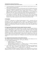
As a first step towards realization of tactile sensing arrays based on the above said approach,
arrays of tactile sensors were developed by directly coupling thin piezoelectric polymers films
to 32 taxel MEAs realized on silicon die, as shown in Fig 2. The MEAs in this case act as the
extended gates of FETs devices, which are external to the chip. Somewhat similar approach is
used by Swartz et al. (Swartz and Plummer 1979) and Fiorillo et al (Fiorillo, Spiegel et al. 1990)
to develop ultrasonic sensors and by Kolasar et. al. (Kolesar, Reston et al. 1992) to develop
tactile sensors. While the former used the epoxy-adhered PVDF film, later one used a thin film
of PVDF-TrFE directly deposited from solution on to the extended gates.
(a)
(b)
Fig 2. a) MEA for the extended gate-FET approach. Chip dimension is 1cm x 1cm. and
diameter of the taxels is 500μm (b) Back and front sides of MEA with 100 μm polymer
covering all the electrodes. A general purpose protecting tape can also be seen. (Dahiya,
Valle et al. July, 2007)
One of the test structures devoted to characterize the polymeric material and to perform the
electrical/mechanical tests to refine the read out electronics is shown in Fig. 2(a). To study
the electrical response of different taxels PVDF-TrFE polymer with 25, 50 and 100 μm have
been deposited. The fabrication steps for these test structures are given in Table 2. The front
Exposed Au
Passivated Metal
Tactile Sensing for Robotic Applications
299
and backside of the MEA after depositing polymer is shown in Fig. 2(b). The fabrication of
MEA is implemented on a fuse silica quartz substrate a Al:Si 1% /Ti/TiN, respectively of
410/30/140 nm thick, low resistance multilayer for both microelectrodes and electrical
connections. The TiN top-layer has been introduced to guarantee a low contact resistance to
the final Au/Cr (5/150 nm) seed-layer. The metal wires passivation has been guaranteed by
a SiO
2
/Si
3
N
4
(20/210 nm) layer deposited by PECVD. These thicknesses have been chosen to
keep the substrate capacitance low and hence to get the maximum of the voltage produced
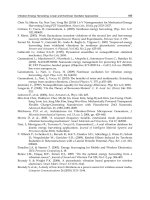
by polymer at the gate terminal. Fig. 3 shows the average response of three touch sensing
elements - to forces up to 0.4 Kgf, when a sinusoidal force was applied at 15 Hz. The response
is linear over a large range of forces. It can be noticed that unlike MEMS based sensors, the
range of detectable force is higher in this case. Similarly the sensors based on silicon
micromachining are known to have a mobility of three orders of magnitude higher that of
organic based devices and hence they have faster response time. A further characterization is
required to study the behaviour of sensing array over broad range of frequency.
Fabrication Process
a.
Substrate: 500 μm thick quartz wafer.
b.
A Ti/TiN/Al/TiN multilayer is deposited by sputtering.
c.
This multilayer is patterned by photolithography and plasma dry etching to form
the electrodes, lines and the contact pin zone.
d.
A layer of Si
3
N
4
(200 nm) is then deposited by PECVD, in order to insulate the metal
lines.
e.
Contacts are opened through the Si
3
N
4
layer by plasma dry etching
f.
Evaporation of Cr and Au is carried out (5 nm and 150nm, respectively)
g. The Chromium and Gold layers are patterned by wet etching.
h.
Deposition of piezoelectric polymer. The film was deposited using epoxy adhesive
on the MEA, covering all 32 taxels. The film was covered with glass slide and the
arrangement was again kept under vacuum to remove air between polymer and
MEA and to ensure uniform thickness of the adhesive. For better adhesion the
arrangement was kept at 65 degrees for thirty minutes.
Table 2. Fabrication steps of piezoelectric polymer-MEA based tactile sensing arrays.
Fig. 3 Average taxels response when variable dynamic force is applied at 15 Hz (Dahiya,
Valle et al. 2008).
Sensors, Focus on Tactile, Force and Stress Sensors
300
6. Conclusion and future development
Despite an important role and being a component of robotics roughly as long as vision, the
use of touch sensing in robots is lesser than other sensory modalities e.g. vision and
auditory sensing, thereby restricting the cognitive capabilities of the robots and strongly
limiting their real world interaction capabilities. The lesser usage of touch sensing could
partly be attributed to the complex and distributed nature of tactile sensing and partly also
to the non availability of satisfactory tactile sensors. The physical problems like placement,
robustness of sensors, wiring complexity etc. also pose a hurdle in effective utilization of
tactile sensors. The interaction of robots with environment through tactile sensing has
largely been limited to the measurement of static interaction forces whereas real world
interaction involves both static and dynamic forces. Similarly, most of the sensors are
designed to measure static pressure or forces from which it is difficult to obtain information
like friction, stickiness, texture, hardness and elasticity. In real world, one needs to measure
all these contact parameters which may require use of more than one transduction method
simultaneously. As an example measurement of stress and stress rate can be done by having
capacitive and piezoelectric transducers. Thus, more and more multifunctional tactile
sensors – very few of which have been reported (Engel, Chen et al. 2005) - are required for
real world interaction.
The pursuit of tactile sensing for robotic applications, in the last two decades, has resulted in
the development of many touch sensors - exploring nearly all modes of transduction -but;
none could produce a tactile analog of CMOS optical arrays. Clearly, the emphasis, `only’ on
the sensor development has resulted in a large number of ‘bench top’ sensors – suitable in a
laboratory environment, and having limited practical usage in the robotic systems. This is
surprising, considering the long history of gripper design for manipulative tasks. It is
believed that the lack of the system approach has rendered many of them unusable, despite
having a good design and performance (Dahiya, Valle et al. March, 2008). It is evident from
the fact that very few works on tactile sensing have taken into account system constraints,
like those posed by other sensors or by the robot controller, processing power etc. As an
example, large numbers of tactile sensors put a pressure on the computing power required
to process large number of data, whereas same can be solved (or at least reduced) by having
distributed computing starting right from the transducer level (Dahiya, Valle et al. March,
2008). A system approach for the tactile sensing can be helpful in filling the gaps between
tactile sensing and other sense modalities.
7. References
Apple Inc. (2008). "iPodtouch."
Beebe, D. J., A. S. Hsieh, et al. (1995). "A Silicon Force Sensor for Robotics and Medicine."
Sensors and Actuators A 50: 55-65.
Berger, A. D. and P. K. Khosla (1991). "Using tactile data for real-time feedback." The
International Journal of Robotics Research 10(2): 88-102.
Bicchi, A., J. K. Salisbury, et al. (1990). Augmentation of grasp robustness using intrinsic
tactile sensing. IEEE International Conference on Robotics and Automation.
Cincinnati, OH. 2: 968-973.
Charlebois, M., K. Gupta, et al. (2000). "On Estimating Local Shape Using Contact Sensing."
Journal of Robotic Systems 17(12): 643-658.
Tactile Sensing for Robotic Applications
301
Cheung, E. and V. L. Lumelsky (1992). "A Sensitive Skin System for Motion Control of Robot
Arm Manipulators." Journal of Robotics and Autonomous Systems 10: 9-32.
Chu, Z., P. M. Sarro, et al. (1996). "Silicon Three-Axial Tactile Sensor." Sensors and Actuators
A 54: 505-510.
Cutkosky, M. R. and I. Kao (1989). "Computing and controlling the compliance of a robotic
hand." IEEE Transactions on Robotics and Automation 5(2): 151-165.
Dahiya, R. S., G. Metta, et al. (2008). "Tactile Sensing: From Humans to Humanoids." IEEE
Transactions on Robotics (unpublished).
Dahiya, R. S., M. Valle, et al. (2008). Tactile Sensing Arrays for Humanoid Robots using
Piezo-Polymer-FET devices. 13th National Conference on Sensors and
Microsystems, Rome, Italy.
Dahiya, R. S., M. Valle, et al. (2008). Deposition Processing and Characterization of PVDF-
TrFE Thin Films for Sensing Applications. IEEE Sensors 2008, Lecce, Italy. (in
press).
Dahiya, R. S., M. Valle, et al. (2008). System Approach-A paradigm for Robotic Tactile
Sensing. The 10th IEEE International Workshop on Advanced Motion Control.
Trento, Italy.
Dahiya, R. S., M. Valle, et al. (2007). Tactile Sensor Arrays for Humanoid Robot. IEEE
PRIME'07, The 3rd International Conference on PhD Research in Microelectronics
and Electronics, Bordeaux, France, IEEE.
Dargahi, J., M. Parameswaran, et al. (2000). "A Micromachined Piezoelectric Tactile Sensor
for an Endoscopic Grasper - Theory, Fabrication and Experiments." Journal of
Microelectromechanical Systems 9(3): 329-335.
Dario, P. and D. de Rossi (1985). "Tactile Sensors and Gripping Challenge." IEEE Spectrum
22(8): 46-52.
Diftler, M. A., R. Platt Jr, et al. (2003). Evolution of the NASA/DARPA Robonaut control
system. IEEE International Conference on Robotics and Automation. Taipei,
Taiwan: 2543-2548.
Domenici, C., D. D. Rossi, et al. (1989). "Shear stress detection in an elastic layer by a
piezoelectric polymer tactile sensor." IEEE Transactions on Electrical Insulation
24(6): 1077-1081.
Ellis, R. E. and M. Qin (1994). Singular-value and finite-element analysis of tactile shape
recognition IEEE International Conference on Robotics and Automation. San
Diego, CA: 2529-2535.
Engel, J., J. Chen, et al. (2005). "Polymer Micromachined Multimodal Tactile Sensors."
Sensors and Actuators A 117: 50-61.
Fearing, R. S. (1990). "Tactile Sensing Mechanisms." The International Journal of Robotics
Research 9(3): 3-23.
Fearing, R. S. and T. O. Binford (1991). "Using a cylindrical tactile sensor for determining
curvature " IEEE Transaction on Robotics and Automation 7(6): 806-817.
Fiorillo, A. S., J. V. D. Spiegel, et al. (1990). "A P(VDF-TrFE) based Integrated Ultrasonic
Transducer." Sensors and Actuators A A21-A23: 719-725.
Flanagan, J. R. and A. M. Wing (1993). "Modulation of Grip Force with Load Force during
point-to-point arm movements." Experimental Brain Research 95: 131-143.
Sensors, Focus on Tactile, Force and Stress Sensors
302
Gray, B. L. and R. S. Fearing (1996). A Surface Micromachined Microtactile Sensor Array.
International Conference on Robotics And Automation, Minneapolis, Minnesota,
USA, IEEE.
Heo, J S., J H. Chung, et al. (2006). "Tactile Sensor Arrays using Fiber Bragg Grating
Sensors." Sensors and Actuators A 126: 312-327.
Howe, R. D. (1994). "Tactile Sensing and Control of Robotics Manipulation." Journal of
Advanced Robotics 8(3): 245-261.
Howe, R. D. and M. R. Cutkosky (1993). "Dynamic Tactile Sensing: Perception of Fine
Surface Features with Stress Rate Sensing." IEEE Transactions on Robotics And
Automation 9(2): 140-151.
Howe, R. D. and M. R. Cutkosky (1990). Integrating tactile sensing with control for dextrous
manipulation. IEEE International Workshop on Intelligent Motion Control.
Istanbul, Turkey. 1: 369-374.
Howe, R. D. and M. R. Cutkosky (1989). Sensing skin acceleration for slip and texture
perception. IEEE International Conference on Robotics and Automation. Scottsdale,
AZ: 145-150.
Interlink Electronics Inc. (2008). "FSR Sensors."
Jamone, L., G. Metta, et al. (2006). James: A humanoid Robot Acting over an Unstructured
World. 6th IEEE-RAS Int. Conf. on Humanoid Robots. Genoa, Italy.
Johannson, R. S. and I. Birznieks (2008). "First Spikes in Ensembles of Human Tactile
Afferents Code Complex Spatial Fingertip Events." Nature Neuroscience 7(2): 170-
177.
Kageyama, R., S. Kagami, et al. (1999). Development of Soft and Distributed Tactile Sensors
and the Application to a Humanoid Robot. IEEE International Conference on
Systems, Man, and Cybernetics.
Kane, B. J., M. R. Cutkosky, et al. (2000). "A Traction Stress Sensor Array for Use in High-
Resolution Robotic Tactile Imaging." Journal of Microelectromechanical Systems
9(4): 425-434.
Klatzky, R. L. and S. J. Lederman (2003). Touch. Experimental Psychology. A. F. Healy and
R. W. Proctor. New York, John Wiley & Sons. 4: 147-176.
Kolesar, E. S., R. R. Reston, et al. (1992). "Multiplexed Piezoelectric Polymer Tactile Sensor."
Journal of Robotic Systems 9(1): 37-63.
Lee, M. H. and H. R. Nicholls (1999). "Tactile Sensing for Mechatronics - A State of the Art
Survey." Mechatronics 9: 1-31.
Li, Z., P. Hsu, et al. (1989). "Grasping and coordinated manipulation by a multifingered
robot hand " International Journal of Robotics Research 8(4): 33-50.
Loomis, J. M. and S. J. Lederman (1986). Tactual Perception. New York, John Wiley and
Sons.
Maheshwari, V. and R. F. Saraf (2006). "High-Resolution Thin-Film Device to Sense Texture
by Touch." Science 312: 1501-1504.
Milighetti, G., T. Emter, et al. (2006). Combined Visual-Acoustic Grasping for Humanoid
Robots. IEEE International Conference on Multisensor Fusion and Integration for
Intelligent Systems, Heidelberg, Germany.
Murray, R. M., Z. Li, et al. (1994). A Mathematical Introduction to Robotic Manipulation,
CRC.
Tactile Sensing for Robotic Applications
303
Novak, J. L. (May 1989). Initial design and analysis of a capacitive sensor for shear and
normal force measurement. IEEE International Conference on Robotics and
Automation. Scottsdale, AZ: 137-145.
Nowlin, W. C. (1991). Experimental Results on Bayes-ian Algorithms for Interpreting
Compliant Tactile Sensing Data IEEE International Conference on Robotics and
Automation. Sacramento, California.
Ohka, M., H. Kobayashi, et al. (2006). Sensing Precision of an Optical Three-Axis Tactile
Sensor for a Robotic Finger. 15th International Symposium on Robot and Human
Interactive Communication (RO-MAN), Hatfield, UK.
Ohmura, Y., Y. Kuniyoshi, et al. (2006). Conformable and Scalable Tactile Sensor Skin for
Curved Surfaces. 2006 IEEE International Conference on Robotics and Automation,
Orlando, Florida, USA.
Omata, S., Y. Murayama, et al. (2004). "Real time robotic tactile sensor system for the
development of the physical properties of biomaterials." Sensors and Actuators A:
Physical 112(2-3): 278-285.
Peratech-Ltd, .
Pressure Profile Systems. (2007). "RoboTouch."
Pressure Sensitive Ink. (2008). "
Ricker, S. L. and R. E. Ellis (1993). 2-D finite element models of tactile sensors. IEEE
International Conference on Robotics and Automation. Atlanta, GA: 941-947.
Rossi, D. D., G. Canepa, et al. (1993). "Skin-like tactile sensor arrays for contact stress field
extraction." Materials Science and Engineering C1: 23-36.
Russell, R. A. and S. Parkinson (1993). Sensing surface shape by touch. IEEE International
Conference on Robotics and Automation. Atlanta,GA: 423-428.
Schmidt, P. A., E. Mael, et al. (2006). "A Sensor for Dynamic Tactile Information with
Applications in Human-Robot Interaction and Object Exploration." Robotics and
Autonomous Systems 54: 1005-1014.
Shikida, M., T. Shimizu, et al. (2003). "Active Tactile Sensor for Detecting Contact Force and
Hardness of an Object." Sensors and Actuators A 103: 231-218.
Shimoga, K. B. and A. A. Goldenberg (1992). Soft materials for robot fingers. IEEE Int. Conf.
on Robotics and Automation, Nice, France, IEEE, Robot & Automat Soc.
Shimojo, M. (1997). "Mechanical Filtering Effect of Elastic Cover for Tactile Sensor." IEEE
Transactions on Robotics And Automation 13(1): 128-132.
Someya, T., T. Sekitani, et al. (2004). " A Large-Area, Flexible Pressure Sensor Matrix with
Organic Field-Effect Transistors for Artificial Skin Applications." PNAS 101(27):
9966-9970.
Swartz, R. G. and J. D. Plummer (1979). "Integrated silicon-PVF2 acoustic transducer arrays."
IEEE transactions on Electron Devices 26(12): 1920-32.
Torres-Jara, E., I. Vasilescu, et al. (2006). A soft touch: Compliant Tactile Sensors for
Sensitive Manipulation. Cambridge, CSAIL, Massachusetts Institute of Technology:
1-8.
Tremblay, M. and M. R. Cutkosky (1993). Estimating friction using incipient slip sensing
during a manipulation task. IEEE International Conference on Robotics and
Automation. Atlanta, GA: 429-434.
Sensors, Focus on Tactile, Force and Stress Sensors
304
Walker, R. (2004). Developments in Dextrous Hands for Advanced Robotic Applications.
10th International Symposium on Robotics and Applications ISORA 2004. Seville,
Spain.
Weiss, K. and H. Worn (2004). Tactile Sensor System for an Anthropomorphic Robotic
Hand. IEEE International Conference on Manipulation and Grasping Genoa, Italy.
Westling, G. and R. S. Johannson (1984). "Factors influencing the force control during
precision grip." Experimental Brain Research 53: 277-284.
Woffenbuttel, M. R. and P. P. L. Regtien (1991). "Polysilicon bridges for the realization of
tactile sensors." Sensors and Actuators A-Phys. 26: 257-264.
Yuji, J i. and C. Sonoda (2006). A PVDF Tactile Sensor for Static Contact Force and Contact
Temperature. IEEE Sensors 2006, Daegu, Korea.
Zhang, H. and E. So (2002). "Hybrid Resitive Tactile Sensing " IEEE Transactions on Systems,
Man, And Cybernetics-Part B: Cybernetics 32(1): 57-65.
16
Fast and Accurate Tactile Sensor System for a
Human-Interactive Robot
Toshiharu Mukai, Shinya Hirano and Yo Kato
Bio-Mimetic Control Research Center, RIKEN
Japan
1. Introduction
With the advent of the aging society, the demand for nursing care for the elderly is
becoming much larger. The application of robotics to helping on-site caregivers is
consequently one of the most important new areas of robotics research. Such human-
interactive robots, which share humans’ environments and interact with them, should be
covered with soft areal tactile sensors for safety, communication, and dextrous
manipulation.
Tactile sensors have interested many researchers and various types of tactile sensors have
been proposed so far. Many tactile sensors have been developed on the basis of micro-
electro-mechanical system (MEMS) technology (for example, (Suzuki, 1993; Souza & Wise,
1997)). They have a high-density and narrow covering area realized by applying MEMS
technology, and as a result, are not suitable for covering a large area of a robot’s surface.
Some tactile sensors suitable for use on robot fingers or grippers have also been developed
(Nakamura & Shinoda, 2001; Yamada et al., 2002; Shimojo et al., 2004). Many of them have
the ability to detect tangential stress and can be used in grasping force control. Their main
target is robot fingers, and consequently they were not designed to cover a large area. There
are also commercially available tactile sensors such as those offered by Tekscan (Tekscan,
2008) based on pressure-sensitive ink or rubber, and KINOTEX
TM
tactile sensors (Reimer &
Danisch, 1999) utilizing the change in the intensity of light scattered by the covering
urethane foam when deformed. However, they are not sufficiently accurate because of
strong hysteresis and creep characteristics.
The idea of covering a large area of a robot’s surface with soft tactile skinlike sensors is
attracting researchers (Lumelsky et al., 2001). Some human-interactive robots for which a
large area of their surface is covered with soft tactile sensors have actually been developed
(Inaba et al. 1996; Tajima et al. 2002; Kanda et al. 2002; Mitsunaga et al. 2006; Ohmura et al.,
2006; Ohmura & Kuniyoshi, 2007). However, the tactile sensors are not suitable for human-
interactive robots, particularly when physical labor using tactile sensation is required. For
example, one tactile sensor in (Tajima et al. 2002) has only 3 values as its output, and another
tactile sensor in (Tajima et al. 2002) is gel-type and cannot be used over a long period
because of the evaporation of the contained water. The tactile sensor in (Mitsunaga et al.
2006) has only 56 elements in total. Flexible fabric-based tactile sensors using an electrically
conductive fabric have also been proposed for covering a robot (Inaba et al. 1996), but the
Sensors, Focus on Tactile, Force and Stress Sensors
306
sensors are binary switches, and are difficult to fabricate. To our knowledge, the tactile
sensor used by (Ohmura et al., 2006) has been the most successful for covering a large area
of a robot’s surface. This tactile sensor is based on similar technology to KINOTEX
TM
, but
uses tiny photoreflectors under urethane foam instead of the combination of light-emitting
diodes, photodetectors, and fiber-optic cables. The tactile sensor is fabricated on a flexible
substrate using photoreflectors and circuitry for driving and communication. Their sensor is
suitable for detecting tactile contact, but the principle of their sensor depends on the
deformation of urethane foam, which inevitably causes strong hysteresis and creep
characteristics. Hence, when accuracy is needed, for example, when tactile feedback control
is required, we need more accurate tactile sensors.
For the realization of a robot with tactile sensation, a real-time acquisition and integration
system for gathering tactile sensor data distributed all over the robot’s body is also needed.
When a robot is covered with tactile sensors, the problems of huge computational load and a
large number of cables arise. Localized processing is an effective solution, and tactile sensors
with distributed processors have been developed. For example, the robot in (Tajima et al.
2002) had multiple MPUs connected by a serial bus, and that in (Ohmura et al., 2006) used a
network composed of local serial buses and a custom-designed ring-type network.
We are developing a robot named RI-MAN (Odashima et al., 2006; Odashima et al., 2007;
Mukai et al., 2008), shown in Fig. 1, with soft areal tactile sensors, as a platform for physical
human-robot interaction research. Our ultimate goal for RI-MAN is to help nurse elderly
people in their daily lives, and this inevitably involves performing hard physical tasks in
complex environments such as hospitals and homes. RI-MAN can physically interact with
humans via soft and whole-body interaction. Having a similar size to a human (158 cm in
height and 100 kg in weight) and a smooth surface without bumps, RI-MAN can perform
the task of lifting up a dummy human in its arms. To skillfully perform such tasks that
involve physical contact with humans, RI-MAN is equipped with soft areal tactile sensors in
five places, the chest and the right and left of the upper arms and forearms.
Fig. 1. RI-MAN with tactile sensors for physical human-robot interaction research
We have developed soft areal tactile sensors for RI-MAN by embedding semiconductor
pressure sensors as pressure-sensing elements in an elastic body (Mukai, 2004; Mukai, 2005),
Fast and Accurate Tactile Sensor System for a Human-Interactive Robot
307
as well as their controllers that can realize localized processing and integration through the
network in a robot. Our primary target is the achievement of physical tasks using tactile
sensation, such as lifting up a human. Because semiconductor pressure sensors have little
hysteresis or creep, our sensors also have an accurate response, although the elastic body
covering causes a little hysteresis and creep. The sensor should be able to detect wide range
of pressure from light finger touch to the load of a human held by the robot arms. The
sampling speed and accuracy should be enough for usage in sensor feedback control. Our
tactile sensors satisfy the requirements for human-interactive robots.
In this paper, we report our tactile sensor, as well as its implementation in a robot. After this
introduction, we first describe specifications necessary for tactile sensors in human-
interactive robots. Next we describe the structure and fabrication method of our tactile
sensor. Next we describe the implementation of the tactile sensor system in our robot RI-
MAN. Then we report experimental results of the sensor itself and sensor usage in the robot.
Finally we conclude our paper.
2. Specifications
In this research, we are aiming to develop soft areal tactile sensors that cover the surface of a
human-interactive robot, and provide a pressure strength and distribution that can be used
to control the manipulation of objects. To make this possible, we need sensors that are soft
like human skin and can cover a large area of a robot’s curved surfaces, for safety and
affinity. We are developing such sensors by embedding small semiconductor pressure
sensors as pressure-sensing elements in an elastic body. The elastic body also contributes to
the removal of undesirable insensitive regions by giving interpolation ability to the sensor.
The preciseness of semiconductor pressure sensors can yield high-accuracy tactile sensors.
Considering the application of tactile sensors to human-interactive robots, we determined
the necessary specifications of our tactile sensor system as follows. First, we require a spatial
resolution of about 10 to 20 mm, referring to the approximately 10 mm resolution of the
human palm and 40 mm of the human forearm. Except for the fingertips, this resolution is
sufficient to realize a resolution similar to that of a human. Next, we consider the
measurable pressure range. When a robot holds a person of 60 kg in its arms with a contact
area of 20×20 cm
2
, the average pressure is 14.7 kPa. Using a safety factor of 6, we require a
pressure range of 0 to 88 kPa. Next, we discuss the measurement resolution. Considering
feedback control using tactile sensation, we require a measurement resolution in which the
contact force caused by typical human-robot interaction is expressed by more than 5 bits.
We believe that feedback control is smooth if the value is expressed with this resolution.
Tactile sensors for robots require tactile sensor controllers suitable to be used in robots. It is
desirable that each controller be in the vicinity of the tactile sensor, with short connections
between sensors and controllers, because the connection requires a large number of cables.
This also reduces electric noise because tactile sensor output is analog, while we can use
digital signals for connections among controllers. This requires the following. Controllers
must be able to form a network for sensor data integration in the robot. Controllers must be
sufficiently small to fit in a robot. Controllers must calculate abstract compressed features
from sensor data. Such compressed features are carried through a narrower bandwidth, to
simplify connection in robot and reduce the possibility of cable breakdown. We also require
that the sampling speed be sufficiently fast for our robotic purposes. The sampling speed
depends on the performance of both the sensor and its controller, so that the total system
Sensors, Focus on Tactile, Force and Stress Sensors
308
should be designed to satisfy this requirement. The sampling speed of sensor data and the
communication speed among controllers should agree with the robot control period. It is
empirically known that, for stable and smooth feedback control, the sampling frequency
should be more than 10 times the resonance frequency of the controlled object (Paul, 1981).
In general, robots have a resonance frequency of 1 to 50 Hz, so that the required sampling
frequency is 10 to 500 Hz, which corresponds to a sampling period of 2 to 100 ms (RSJ,
2005).
3. Structure and fabrication method of the tactile sensor
3.1 Basic structure and components
As pressure-sensing elements, we adopted FUJIKURA FPBS-04A pressure sensors (Fig. 2).
These are very small (φ5.8 mm) piezoresistive semiconductor pressure sensors that can
detect absolute pressure between 42.6 and 434.7 kPa. Each sensor has a resistive bridge on
its diaphragm and the output changes almost linearly with the applied pressure.
Fig. 2. Small FUJIKURA semiconductor pressure sensors
To reduce the number of cables leading out from the tactile sensors, we designed a scanning
circuit, an example of which including 4x4 elements is shown in Fig. 3. By changing
switches, we can select a row and a column to obtain the output from the selected element.
In this example, the top-left element is selected by switching. All outputs of the pressure-
sensing elements are obtained by scanning this array. The actual circuit we made has an
array of 8x8 pressure-sensing elements with an 18 mm pitch. This pitch was determined to
satisfy the above requirement to realize a spatial resolution similar to a human. We
fabricated the circuit as a flexible printed circuit (FPC), so that it can be fit onto a 2D-curved
surface (which can be expanded into a 2D plane) because of its flexibility. We call the FPC
sheet with the pressure-sensing elements and other electronic parts as ‘sensor sheet’. To
mount it onto a free-curved surface (which cannot be expanded into a 2D plane), we
designed the circuit so that all the wiring is concentrated into a comb-shaped region. Thus,
the sensor sheet can be cut into a shape consisting of thin regions. After cutting, the sheet
can be wound onto a free-curved surface, as shown in Fig. 4, if the curvature is not too
sharp. In addition, we designed the circuit all of which wiring concentrates into a comb-
shaped region, so that it works if the central part remains even when the marginal parts are
cut off. Therefore it can be applied to a smaller surface than the original sensor sheet. To
reduce cables, we also put analog switches and an instrumentation amplifier on the FPC. As
a result, the number of cables has become 10. As the instrumentation amplifier, we adopted
a digital amplifier that can select its gain from 1, 2, 4, and 8. If this amplifier gain needs to be
controlled, additional two cables are needed.
Fast and Accurate Tactile Sensor System for a Human-Interactive Robot
309
Fig. 3. Circuit of our tactile sensor
Fig. 4. Sensor sheet that can be cut into a comblike shape and wound on a curved surface
3.2 Method of fabricating a curved tactile sensor
To make the tactile sensors soft, we embedded the sensor sheet in an elastic body.
First, the sensor sheet is fixed after it is wound around the curved surface. Next, to remove
gaps between the shells of pressure-sensing elements, the gaps are filled with a plastic
material that hardens after the desired form is reached. Then, a small projection-shaped
piece of elastic material is placed on the diaphragm of each pressure-sensing element. After
that, an elastic sheet covers the above assembly. Fig. 5 shows a schematic of the structure of
our curved tactile sensor. We used paper clay to fill the gaps, liquid rubber to fabricate the
projection-shaped pieces, and a 5-mm-thick sponge sheet as the elastic sheet.
Sensors, Focus on Tactile, Force and Stress Sensors
310
Fig. 5. Schematic structure and a photo of our curved tactile sensor
We selected the material of the elastic projection-shaped pieces to be harder than the elastic
sheet. As a result, the small pieces push up against the elastic sheet, and the regions around
the pieces in the sheet are compressed and become denser than the other regions. Thus, hard
and soft areas appear in the elastic sheet (Fig. 5), and this structure has an amplifying effect
(Mukai, 2005). A photograph of our curved tactile sensor is also shown in Fig. 5.
4. Implementation of a tactile sensor system
We installed the tactile sensors in our robot RI-MAN in five places, the chest and the right
and left of the upper arms and forearms. Each sensor sheet has 8x8 elements, so that RI-
MAN has 320 pressure-sensing elements in total. To process enormous sensor data in
realtime in the vicinity of sensor, we developed a tactile sensor controller based on a dsPIC
board (Landmark LM517), a picture of which is shown in Fig. 6.
(a) Front and back view (b) Stacking with extension board
Fig. 6. dsPIC board for general sensing/controlling purposes
The dsPIC board is a general purpose sensing/controlling board developed by us, with a size
of 35x50 mm
2
. It is equipped with a dsPIC (Microchip technology 30F6012A) as the CPU and a
USB interface IC (FTDI FT232RL) that realizes 1 Mbps communication. It also has many
connectors through which many pins can be accessed. It also has a stacking connector for an
extension board. The tactile sensor controller we developed uses a 12 bit A/D converter and
digital I/Os in the 30F6012A. Its program is written in the C language and downloaded in the
flash memory of the 30F6012A, as the firmware. The C program determines how to compress
data from a tactile sensor sheet into abstract features suitable for network communication.
Fast and Accurate Tactile Sensor System for a Human-Interactive Robot
311
Using this board, up to 1 ms sampling of 1 tactile sensor sheet can be realized. We also
developed an extension board for network communication, to connect the tactile sensors to
the network in our robot RI-MAN. It has a network IC (Step Technica MKY40) that realizes a
virtual shared memory, the maximum size of which is 512 byte. The guaranteed
synchronization time of the virtual shared memory depends on the memory size, and is 1
ms for 256 byte and 2.4 ms for 512 byte. The extension board can be stacked with the dsPIC
board as shown in Fig. 6(b). The small size and the network communication ability of our
tactile sensor controller enable us to install them distributedly in the robot body. The
communication can be realized using only 2 cables, which largely simplifies wiring and
reduces maintenance cost in the robot.
In the virtual shared memory space, each node occupies an area consisting of stations one of
which corresponds to 8 byte. In RI-MAN, various sensor controllers and motor controllers
are connected to the network and, as a result, the area that tactile sensors can use is limited.
In the current implementation, the host PC (with RT-Linux) occupies 1 station to send
commands (for setting modes and parameters) through network to tactile sensors, and each
of 5 tactile sensor controllers occupies 3 stations.
Each tactile sensor has only 3 stations, corresponding to 24 byte, for communication, thus all
of 8x8 sensor element values (which is expressed by 12 bit) cannot be transmitted
simultaneously. It is possible to send data line by line and combine them in the host PC to
obtain whole output of one sensor sheet, but this takes unacceptable time (about 90ms) for
feedback control. So we determined to calculate geometric moments in local controllers and
transmit only the moments through network. The geometric moments are expressed, using
element value
xy
I
at
),( yx
, as follows.
Zeroth:
∑
=
yx
xy
IM
,
0
First:
∑
=
yx
xyx
xIM
,
,
∑
=
yx
xyy
yIM
,
Second:
∑
=
yx
xyxy
xyIM
,
,
∑
−=
−
yx
xy
yx
IyxM
,
22
)(
22
The zeroth moment is the total sum itself, and the centroids (center of pressure) can be
obtained by dividing the first by the zeroth. Using up to the second moments, we can obtain
the axis of least inertia (Horn, 1986), which is the orientation of the object, as shown in Fig. 7.
In the controller using dsPIC, all of data acquisition and calculation finishes in 2 ms.
Fig. 7. The axis of least inertia
))((),(2arctan(
2
1
22
00
22
yxMMyxMM
yx
xy
−−−=
−
θ
θ
),( yx
Axis of least inertia
Sensors, Focus on Tactile, Force and Stress Sensors
312
5 Experimental results
5.1 Basic performance of the sensor
We conducted experiments to investigate the basic performance of our tactile sensor system.
Flat tactile sensors with the 5-mm-thick elastic sheet were used to investigate the basic
performance. In experiments where a dynamic force was needed, the experimental setup
shown in Fig. 8 was used. The setup consisted of a digital force gauge, a load cell (Minebea
LSM-1K-B), a vibrator (Asahi SeisakusyoWaveMaker01), and an XY stage. The force gauge
was used to approximately measure the applied force to ensure that an excessive force was
not exerted. Actual measurement of the applied force was carried out using the load cell,
which has higher accuracy. The vibrator was used to generate controlled dynamic motion,
and the force was exerted using a rod with a circular tip with a diameter of 8 mm. In
experiments where a force over a wider area was needed, weights were used. However, in
this case, the force was limited to a static force. Outputs from pressure-sensing elements
were digitized by an A/D converter in the tactile sensor controller and sent to a PC through
USB connection. These values are referred to as ‘sensor output’. The unit of sensor output
corresponds to 0.00122 V, and the sampling period of the measurement was 1 ms. The
amplifier gain of sensor sheets were fixed to 8 in all experiments.
Fig. 8. Experimental setup
a) Response to a sinusoidal wave
First, we show, in Fig. 9, the measured time response of a pressure-sensing element (with
the covering sheet) along with the applied force, when vibrated with a 1, 10, or 100 Hz
sinusoidal wave. The force was applied from immediately above the element using the rod
with the 8 mm circular tip. We can see that the time response has a smooth sinusoidal shape
at 1 and 10 Hz, though the shape is slightly deformed at 100 Hz. A typical relationship
between the applied force and the sensor output at 1 Hz is shown in Fig. 10. The sensor
output is almost linear with the applied force. The solid line in the graph is the linear
approximation
ax
y
=
based on the results (from 3000 samples), where
35.13
=
a
in this
case. This slope is referred to as gain in this paper. From this experiment, we can also see
that our sensor has satisfactory measurable range and measurement resolution discussed in
Section 2. When a force of 8 N was applied using the rod with the 8 mm circular tip, the
pressure was about 159 kPa and the sensor output was more than 90. These results satisfy
the required maximum range of 88 kPa and 5 bit resolution.
Fast and Accurate Tactile Sensor System for a Human-Interactive Robot
313
0
10
20
30
40
50
60
70
80
90
100
0 500 1000 1500 2000
Time [ms]
Sensor output (one element
)
0
1
2
3
4
5
6
7
8
Applied force [N]
Sensor output
Applied force
0
10
20
30
40
50
60
70
80
90
100
0 50 100 150 200
Time [ms]
Sensor output (one element
)
0
1
2
3
4
5
6
7
8
Applied force [N]
Sensor output
Applied force
46
48
50
52
54
56
58
60
0 5 10 15 20
Time [ms]
Sensor output (one element
)
3
3.2
3.4
3.6
3.8
4
4.2
4.4
4.6
4.8
5
Applied force [N]
Sensor output
Applied force
(a) 1 Hz (b) 10 Hz (c) 100 Hz
Fig. 9. Response of a pressure-sensing element to sinusoidal force
y = 13.35x
0
20
40
60
80
100
02468
Applied force [N]
Sensor output (one element
)
Fig. 10. Force vs sensor output
b) Variations of pressure-sensing elements
Next, we checked the variations of pressure-sensing elements on a sensor sheet. A
sinusoidal force of 1 Hz was applied from immediately above the element using the rod
with the 8 mm circular tip. The results of 20 elements are shown in Fig. 11. The standard
deviation is about 6.5% of the averaged gain. The gains varied partly because we manually
fabricated the projection-shaped elastic pieces on the diaphragms. We expect that if we
make them by a more controlled method, the variation will decrease.
0
2
4
6
8
10
12
14
16
0 5 10 15 20
Element number
Gain at 1 H
z
Average: 12.31
Standard deviation: 0.800
(n=20)
Fig. 11. Variations of elements on a sensor sheet
c) Frequency response
The results of experiments to investigate frequency response are shown in Fig. 12. The output
was measured from a certain pressure-sensing element in a tactile sensor, and gain was
normalized to 1 at 1 Hz. The decrease of gain at 100 Hz is 3 dB and the phase delay is 20
degree, approximately. These results show that our sensor can detect high-frequency signals.
Sensors, Focus on Tactile, Force and Stress Sensors
314
Fig. 12. Frequency response of a sensing element
d) Interpolation ability
Interpolation ability is obtained because of the covering elastic sheet even though discrete
pressure-sensing elements are located separately. This removes undesirable insensitive
region on the tactile sensor. Experimental results for verifying this effect are shown in Fig.
13. By applying a force using the rod with a tip diameter of 8 mm at a certain distance away
from the element, gains in the graph were measured. The gain was normalized to 1 at the
distance 0. The response shape agrees with the theoretically calculated values in (Shimojo,
1997).
0
0.2
0.4
0.6
0.8
1
0 0.2 0.4 0.6
Distance from the element [taxel]
Gain
Fig. 13. Results of interpolation test
e) Hysteresis and drift
The results of experiments for investigating hysteresis are shown in Fig. 14. A load of 6.75 N
approximately was applied and removed in about 5 s. Hysteresis exists but it is small. Next,
to see longer-term effect (drift), a 668 g weight with an area of 52x44 mm
2
was placed on the
sensor for 10 minutes. The sum of outputs from all elements is shown in Fig. 15. The output
reduced slightly but it is about 4% of the initial output.
Fast and Accurate Tactile Sensor System for a Human-Interactive Robot
315
0
1
2
3
4
5
6
7
0 2000 4000 6000 8000
Time [ms]
Load [N]
-10
0
10
20
30
40
50
60
70
80
90
100
012345678
Force [N]
Sensor output (one element
)
(a) Time profile of applied force (b) Force vs sensor output
Fig. 14. Results of hysteresis test
0
20
40
60
80
100
120
140
160
0246810
Time [min]
Sensor output (sum of all elements
)
Fig. 15. Drift over 10 minutes
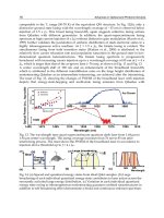
5.2 Tactile sensors in a robot
The output of all tactile sensors when holding a dummy human weighing 18 kg in its arms
is shown in Fig. 16. The size of each square represents the amplitude of the corresponding
tactile sensor element in log scale. This data were obtained and recorded in the host PC by
Fig. 16. Tactile sensor output when holding a dummy human weighing 18 kg