Robotics and Automation in Construction 2012 Part 4 docx
Bạn đang xem bản rút gọn của tài liệu. Xem và tải ngay bản đầy đủ của tài liệu tại đây (3.65 MB, 30 trang )
Robotics and Automation in Construction
84
allows for easy development of cost estimates that can be used both for cost estimating and
cost control.
The process provides the project participants, and primarily the project managers, with the
ability to analyze and visualize multiple design alternatives in order to develop the most
cost-effective and constructable solutions. It consequently allows for better control and
decision making over different constructability issues and schedule scenarios, providing in
this manner a linkage between constructability, 4D, and cost estimating.
The time and the cost required for the development initially of the 3D model and
sequentially the 4D model restrict the use of the process to projects with constructability
and/or visualization issues. In these cases it is considered necessary for the understanding
of the construction sequence and budget issues from all the project participants. Especially
in large scale projects it can also facilitate the decision-making, allowing for faster
authorization. The applications of this process include all civil works such as buildings, civil
infrastructure and industrial projects. It could also be used both within an owner and a
contractor organization while developing their cost estimates and/or reviewing
constructability plans.
The anticipated benefits and the long term contributions of this research are expected to be
numerous. The proposed process allows for improving the information exchange within the
AEC industry by providing a better communication of building related information between
the design and construction phases in a project. Since the scheduler uses the data generated
by the designer, cost estimates become more accurate and margins for errors and omissions
in schedule are reduced. Avoiding reentering data and filling the communication gaps,
money and time are saved, as the information is directly received from the 3D model.
The proposed method addresses interoperability and brings the AEC industry one step
closer to n-D CAD. Ultimately the proposed process for integrating cost into 4D models will
contribute to the development of infrastructure methodologies and technologies that allow
for the integration of construction parameters, such as buildability, accessibility,
sustainability, and maintainability into the 3D model.
7. References
Bennet, C., and Ditlinger, S. (1994). Bechtel Automated Lift Planning System. Robotics for
challenging environments. New York, N.Y.: ASCE, 1994.
Bjornsson, H. (2003) IT Revolutionises Construction. 1998. Building Innovation and
Construction Technology. Available: />08/itrevolution.htm. October 2003.
Brown & Root Braun. C.A.R.: Computer Aided Rigging Manual. Houston, TX.
Building Lifecycle Interoperable Software (BLIS) (2003). Blis Home Page. Available:
November 2003
Dallas High Five (2003). Available: . November 2003.
Elzarke, H. (2001). Computer Integrated Construction for Small and Medium Contractors.
ASC 37th Annual Conference. Denver, Colorado, 255-62.
Feigenbaum, L. (2002). Construction Scheduling with Primavera Project Planner. Second ed.
Upper Saddle River, N.J.: Pearson Education.
Fischer, M., and Kam, C. (2003) 4D Modeling Application Case Studies. SIENE Workshop on
4D modeling. Available: siene/
4D%20Application%20Case%20Studies-3.pdf.
Towards n-D Construction Visualization: Cost Integration into 4D Models
85
Gao, J. and Fischer, M. (2006). 4D CAD on Building Construction Projects: Benefits for
Project Success and Controllable Implementation Factors, Construction Informatics
Digital Library
Goldberg, H. E. (2003). Estimating Software Taps into Cad Building Model Data.
CADALYST. Available:
ctools/ 0902 aectools.htm. November 2003.
Gould, F. E., and Nancy E. J. (2003). Construction Project Management. Second ed. Upper
Saddle River, N.J.: Pearson Education, 2003.
Holness, G. (2003). V.R. Smart IM for Project Man. January 2003. ASHRAE. Available:
http:// www.leanconstruction.org/pdf/holness_1.pdf. November 2003.
IAI North America (2003). New Member Brief. 2003. Available:
membership/membership_brief.php. November 2003.
International Alliance for Interoperability (2003). I.F.C. Resources. 2003. Available: http://
www.corenet.gov.sg/it_standards/iai/5_IFC_Resources.htm. November 2003.
Jspace Class Editor User Guide. Bentley, 2002.
Khemlani, L.(2003). Interoperability and the Solibri Model Checker. November 2002.
CADENCE AEC Tech News. Available:
newsletter/aec/1102_2.html. November 2003.
Lee, A., et al. (2002). Developing a Vision for an nD Modeling Tool, CIB w78 Conference.
Aarthus School of Architecture, Denmark: International Council for Research and
Innovation in Building and Construction, 2002.
Lee, A., Wu, S., Marshall-Ponting, A., Aouad, G., Tah, J., Cooper, R., and Fu, C. (2005) n- D
modelling – a driver or enabler for construction improvement, RICS Research paper
series , University of Salford,United Kingdom.
Liapi, K., Kwaja, N., O’ Connor, J. (2003). Highway Interchanges: Construction Schedule and
Traffic Planning Visualization, 2003 Transportation Research Board (TRB) Annual
Meeting, Proceedings, Liapi January 18, 2003, Washington DC. CD ROM.
Liapi, K. (2003). 4D Visualization of Highway Construction Projects , IEEE, Seventh
International Conference on Information Visualization, Proceedings, July 14-17, 2003,
London, GB, 639-644.
Ling, K-L., and Haas, C.T. (1996). An Interactive Planning Environment for Critical
Operations, Journal of Construction Engineering and Management , 212-22.
McKinney, K., and Fischer, M. (1998). Generating, Evaluating and Visualizing Construction
Schedules with Cad Tools., Automation in Construction 7.6 , 433-47.
Microstation Triforma User Guide. Bentley, 2003.
Navigator User Guide. Bentley, 2003.
Paschoudi, Th.(2003). Cost Integration into 4D models, Thesis,University of Texas, at Austin.
Retik, A., and Shapira A. (1999). VR-Based Planning of Construction Site Activities.
Automation in Construction 8.6 (1999): 671-80.
Saad, I.M., and Batie, D. (2002). The Science and Technology Building 4D Construction
Model. 2002. Southeast Section Conference, ASEE. Available:
/ciitr/ ASEE2002.pdf. December 2002.
Sanvido, V.E., and Madeiros, D.J. (1990). Applying Computer-Integrated Manufacturing
Concepts to Construction, Journal of Construction Engineering and Management 116.2
(1990): 365-79.
Robotics and Automation in Construction
86
Sriprasert, E., and Dawood, N.(2001). Potential of Integrated Digital Technologies (IDT) for
Construction Workforce Instruction, Conference at Chalmers, Gothenburg Sweden:
AVR II, 2001. 136-45.
Staub-French, S., and Fischer, M. (2003). Practical and Research Issues Using Industry
Foundation Classes, Center for Integrated Facility Engineering. Available:
2003.
Staub-French, S., and Fischer, M. (2000). Formalisms and Mechanisms Needed to Maintain
Cost Estimates Based on an IFC Product Model. ICCCBE-VIII, Stanford University.
TIMBERLINE. Cad Integrator (2003). Available:
pdfs/cad_integrator.pdf. October 2003.
Tollefsen, T. & Haugen, T. (2007). 3D AND 4D Modeling for Design and Construction
coordination: Issues and lessons learned, EDITOR: B-C Björk
/2007/26/
TxDOT (2003). TxDOT's High Five Interchange Project Ahead of Schedule. August 2003.
TxDOTExpressway. Available :
058%2D2003.htm. October 2003.
Vargese, K., and O'Connor, J.T.(1995). Routing Large Vehicles on Industrial Construction
Site. Journal of Construction Engineering and Management 121.1 (1995): 1-12.
6
Developing Construction CAD-Based
Experience Management System
Yu-Cheng Lin
National Taipei University of Technology/ Civil Engineering
Taiwan
1. Introduction
Experience is valuable, stored specific knowledge obtained by a problem-solving agent in a
problem-solving situation (Bergmann, 2002). Construction experience is knowledge that is
based on construction methods, field operations and results of prior projects. Construction
experience transfer is the use of knowledge gained in previous projects to maximize
achievement of current project objectives (Reuss &Tatum, 1993). Although knowledge
management is already well established in the construction industry, experience
management (EM) is a new concept in information systems. Knowledge management (KM)
is the collection of processes governing the creation, storage, reuse, maintenance,
dissemination and utilization of knowledge. Experience is the life blood of individuals and
organizations, and EM, a sub-discipline of KM, refers to the collection of processes
controlling the creation, storage, reuse, evaluation and usage of experience in a particular
situation or problem solving context. To transfer experience between similar projects,
construction professionals have traditionally used techniques ranging from formal annual
meetings to face-to-face interviews (Reuss and Tatum, 1993). To realize potential benefits,
construction experience should influence all phases of a project (Tatum, 1993). Furthermore,
knowledge gained from experience often requires action and may add cost-effective scope
to other functional actions to avoid repeating past problems (Tatum, 1993). EM focuses on
the acquisition and management of important issues and experience from participating
engineers. Useful experience can be recorded in different forms and media, such as in the
minds of experts, in operating procedures or in documents, databases and intranets. EM in
the construction field aims to effectively and systematically transfer and share experience
among engineers.
This study views experience as the knowledge gained by executing construction projects. To
enhance the quality of EM gained by engineers involved in construction projects, this study
proposes a Computer-aided Design (CAD)-based Maps (CBM) approach to achieving EM
solutions in the construction industry. Combined with web-based technology and CBM, this
study proposes a Construction Web-based Dynamic CAD-based Maps Experience
Management (CBMEM) system enabling engineers to reuse domain knowledge and
experience by dynamically exchanging and managing experience during the construction
phase of a project. In the proposed CBMEM system, the map-based experience exchange
environment enables engineers to manage and dynamically share their experience with
Robotics and Automation in Construction
88
other engineers in current projects. Engineers are, thus, invited to exchange and share their
experience, and construct valued content through their own experience. In this study of a
Taiwan construction building project, the survey (questionnaire) results indicated that the
CBMEM system, integrated with a CBM approach is effective for construction experience
exchange and management.
2. Problem satement
Unlike manufacturing, each construction project is designed and executed to serve specific
needs of the owner. The nature of the work and the constitution of the work force in a
construction project change with time (Manavazhi, 1995). Experience provides strength in a
competitive business environment. Thus, effectively leveraging experience is essential to
business success. The complicated nature of the construction industry makes it an important
field for experience management (EM), particularly regarding experience gained from
completed projects. Sharing experiences between engineers can improve construction
management during the construction phases of projects, thus helping avoid mistakes that
past projects have already encountered. Transferring construction experience between
projects can significantly contribute to achieving project objectives such as cost, schedule,
quality and safety (Reuss & Tatum, 1993). Learning from experience, also, avoids problem-
solving from scratch, i.e., problems that have already been solved need not be solved
repeatedly. However, no effective platforms are available to assist engineers or experts in
exchanging and sharing their know-how and experiences when contractors execute
construction projects. The inability to share the experience of engineers and experts
represents a major loss for contractors in the construction industry. When completing
projects, these engineers and experts typically accumulate domain knowledge and valued
experience, but share little or no experience with others. In view of EM, these significant
issues and experiences of construction engineers and experts are particularly valuable due
to associated factors such as manpower, significant cost and time.
The primary problems derived from the questionnaire survey of twenty junior and senior
engineers from five participating construction building projects, in the sharing and
exchanging of experience, specifically during the construction phase of projects, are as
follows: (1) difficulty in determining which engineers and experts have helpful and relevant
experience; (2) limited efficiency and quality when using only document-based media for
experience management; (3) difficulty in finding engineers with relevant experience in
similar projects; (4) inadequate documentation of unofficial discussion and communication
regarding problem solving for future reuse; (5) tendency for engineers to communicate
orally in person or by telephone; and (6) unease with illustrating experience in current
commercial information management systems. Documenting and applying experience may
avoid problem-solving from the outset, i.e., problems already solved need not be solved
repeatedly. However, few suitable design platforms have been developed to assist engineers
in illustrating and sharing their experiences when needed. Although enterprises in the
A/E/C industry have begun to collect and store explicit information in enterprise
databases, they have not always been successful at retrieving and sharing tacit knowledge
(Woo et al., 2004). Sharing and using previous tacit experiences in construction projects is,
therefore, the primary and significant challenge of this study.
Developing Construction CAD-Based Experience Management System
89
3. Research objectives
This study proposes a novel and practical methodology for capturing and representing the
experience and project knowledge of engineers by utilizing a Computer-aided Design
(CAD)-based Maps (CBM) approach. Furthermore, this study develops a Construction
Dynamic CAD-based Maps Experience Management (CBMEM) system for engineers. The
CBMEM provides a dynamical experience exchange and management service in the
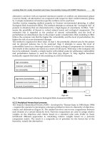
construction phase of a project for the reuse of domain knowledge and experience (see Fig. 1
). Contractors often execute similar projects; accordingly, the problems encountered in like
projects can provide a reference for comparable projects in the future. The capture, transfer,
reuse and maintenance of construction project experience are, thus, critical (Kamara et al.,
2002). To be competitive, a contractor needs to make innovative use of knowledge,
accumulate experience through previous projects and apply it in relevant projects. Senior
engineers that participate in projects act as knowledge workers; they facilitate the collection
and management of experience between current and past projects.
Project Management
Page: 16/9/96
Page: 1
6/9/96
Page: 16/9/96
Page: 1
6/9/96
Page: 16/9/96
Page: 1
6/9/96
Page: 16/9/96
Page: 1
6/9/96
Page: 1
6/9/96
Page: 16/9/96
Page: 1
6/9/96
Page: 16/9/96
Page: 1
6/9/96
Page: 1
6/9/96
Page: 1
6/9/96
Page: 1
6/9/96
Page: 16/9/96
Page: 1
6/9/96
Page: 16/9/96
Page: 1
6/9/96
Page: 16/9/96
Page: 1
6/9/96
Page: 16/9/96
Page: 1
6/9/96
Page: 16/9/96
Page: 1
6/9/96
Page: 16/9/96
Page: 1
6/9/96
Page: 16/9/96
Page: 1
6/9/96
Page: 16/9/96
Page: 1
6/9/96
New Project
Reuse Experience
CAD-based Maps
Page: 1
6/9/96
Page: 16/9/96
Page: 1
6/9/96
Page: 16/9/96
Completed
Project
Manage Construction Project
Exchange Experience
Reuse Experience
Search Experience
Save Experience
Page: 1
6/9/96
Page: 1
6/9/96
Page: 1
6/9/96
Page: 1
6/9/96
Page: 1
6/9/96
Page: 16/9/96
Page: 1
6/9/96
Page: 16/9/96
Fig. 1. The application of experience management in construction projects.
Robotics and Automation in Construction
90
This study concentrates on new approaches for managing and reusing past specific
experience for a construction project framework. With the newly proposed CBM approach
and integration of web-based technology using EM techniques, service engineers and
practitioners can exchange original ideas, experience, knowledge and commands. By
integrating CBM and web-based technology, engineers can obtain problem solutions and
experience directly from senior engineers, decreasing the time and reducing the cost of on-
the-job training. By exchanging and sharing previous experiences among engineers, similar
and related experiences used to execute similar projects can clarify domain knowledge and
enable the exchange of knowledge through web-based EM. The CBMEM system provides a
service to users who can request assistance from selected or all engineers in the enterprise
who have relevant experience. The user can also submit a problem description through
CBM. Moreover, senior and junior engineers can effectively and easily exchange concepts
and experience regarding a specific aspect of their current construction project.
To apply EM to new or other construction projects, the process and content of project
experience must be collected, recorded and stored effectively in the CBMEM system. To
assist the participating engineers in illustrating and managing their own project experience,
CAD-based mapping is presented to help them explore their acquired experience. The main
objectives of this study are as follows: (1) enhance the illustration capabilities using the CBM
approach of captured experience of engineers and experts related to construction projects;
(2) optimize the communication of tacit experience among participating engineers in the
exchanging environment; and (3) design an efficient web-based platform and maps for users
to effectively locate parallel experience from relative engineers. The CBMEM system is then
applied in selected case studies of a Taiwan construction building project to verify the
proposed approach and demonstrate the value of sharing experience in the construction
phase.
4. Background research
4.1 Previous research in experience management In the construction industry
Experience management (EM) deals with collecting, modeling, storing, reusing, evaluating
and maintaining experiences (Bergmann, 2002). In the construction industry, EM is a
discipline that promotes an integrated approach to the creation, capture, sharing and reuse
of the domain knowledge of a profession obtained from projects that have been previously
undertaken. Most project-related problems, solutions, experience and know-how are in the
minds of individual engineers and experts during the construction phase of a project.
Implicit experience is generally undocumented or stored in a system database. To preserve
implicit experience as corporate property, capturing the implicit experience and making it in
the form of explicit experience is a vital aspect of EM. Two broad categories of experience
are tacit experience and explicit experience. Tacit experience is personal, context-specific
experience that is difficult to formalize, record or articulate; it is stored in the minds of
people (Malhotra, 2000). Tacit experience is personal knowledge acquired through
individual experience, which is shared and exchanged through direct, face-to-face contact
(Malhotra, 2001). Explicit experience can be codified and transmitted in a systematic and
formal language, and can be obtained from documents, including reports, articles, manuals,
patents, pictures, images and video (Malhotra, 2000; Tiwana, 2000).
Numerous research efforts have focused on applications of knowledge management in
construction. A Hong Kong study examined the main barriers to effective knowledge
Developing Construction CAD-Based Experience Management System
91
sharing, as well as critical factors and benefits in the construction companies in Hong Kong
and the United Kingdom (Fong & Chu, 2006). Intelligent representation structures store and
access construction domain knowledge and couple it with advanced planning tools to
facilitate rapid formulation and assessment of initial construction project plans
(Udaipurwala & Russell, 2002). Fong et al. (2007) pointed out that the knowledge-creating
capability of value management teams not only enhances the reputation of value
management, but also, helps to dispel the perception of value management as an outdated
problem-solving tool.
4.2 Previous research on knowledge maps in construction
A knowledge map includes the sources, flows, and points of knowledge within an
organization (Liebowitz, 2005). All captured knowledge can be summarized and abstracted
through the knowledge map. The knowledge map, also, provides a blueprint for
implementing a knowledge management system. Well-developed knowledge maps help
users identify intellectual capital, socialize new members and enhance organizational
learning (Wexler, 2001). A knowledge map is a consciously designed medium for
communication between makers and users of knowledge by a graphical presentation of text,
model numbers or symbols (Wexler, 2001). Knowledge mapping helps users understand the
relationship between stored knowledge and dynamics. Knowledge maps have been applied
in various applications, including development of knowledge maps for knowledge
management software tools (Noll et al., 2002).
Numerous research efforts have focused on the use of knowledge maps to support various
knowledge management tasks (McAleese, 1998). Davenport & Prusak (1998) observed that
developing a knowledge map involves locating significant knowledge in an organization
and publishing a list or image that indicates a roadmap to locate it. Mind maps (Buzan &
Buzan, 1993) illustrate the structure of ideas in an associative manner which attempts to
represent how ideas are stored in the brain. A concept map provides a structure for
conceptualization by groups developing a concept framework that can be evaluated by
others (Trochim, 1989). Dynamic knowledge mapping can assist in the reuse of experts’ tacit
knowledge (Woo et al., 2004).
5. Methodology- CAD-based maps
Although maps of knowledge representation have been developed for knowledge-based
applications, no knowledge map has been developed for experience management (EM) in
construction. To assist engineers in extracting the knowledge gained from their own
experience in projects with which they have been involved, this study proposes a novel
dynamical Computer-aided Design (CAD)-based Maps (CBM) approach for the application
of EM in construction. Dynamical CBM help to efficiently illustrate the experiences in the
minds of engineers to generate and organize experience within a construction project
framework. Dynamical CBM are based on associations flowing outward from a central
image in a free-flowing, yet organized, and coherent way. The above content also functions
as the experience acquisition tool in the Construction Dynamic CAD-based Maps Experience
Management (CBMEM) system. Furthermore, engineers may access and edit many
resources, as attachments, in the system. Hence, the CBMEM system can provide engineers
with an experience exchanging environment, as well as a web-based platform for acquiring
experience from more seasoned engineers.
Robotics and Automation in Construction
92
5.1 Concept of CAD-based maps
The proposed CBM are specific approaches to EM in the construction field. Although
knowledge and concept maps are easily recognized in knowledge management, the
proposed dynamical CBM approach is a novel concept and is specific to construction EM.
CBM can be defined as a diagrammatic and graphic representation of experience linking
relationships between experience and attributes of CAD. The CBM mainly provide
assistance for easily and effectively obtaining the necessary experience of users. The primary
advantages of CBM are as follows: (1) CBM are simply, clearly and dynamically represented
in the CBMEM (the EM system); (2) users can easily navigate the CBMEM in order to: a)
understand and determine which engineers and experts own special experience related to a
problem as it arises, and b) edit their experience based on what the situation may require; (3)
CBM enable users’ ability to expand flexible experience illustration and linkage; and (4)
CBM enhance the available visual experience illustration in the CAD maps.
CBM are designed to be easily integrated with CAD and their construction experience. The
key reason for using CBM is the ease with which the combined experience can be
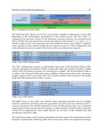
understood and reapplied. Figure 2 illustrates an overview and conceptual framework of
CBM utilized in construction EM. Like construction project management, EM is based on
the concept of undertaking project planning and control activities. Experience gained from
activities in previous projects can be collected, managed and applied in future projects.
Acquired experience from participating engineers can be accessed and saved as map units in
categories for efficient collection, management and finally, retrieval for use in the current
projects.
Function Service
Senior Engineers
Experts
CAD-based Experience Maps
Junior Engineers
Experience
Management Team
Experience Attribute
Experience Validation
Experience Acquisition
Experience Worker
Experience Sharing
E-learning
Experience Units
Experience Units
Fig. 2. The application of CAD-based Maps in experience management
Developing Construction CAD-Based Experience Management System
93
5.2 Framework of CAD-based maps
CAD-based Maps (CBM) are defined in multiple levels, and constructed from variables
which can be broken down by decomposing the experience units into smaller map units into
which the acquired experience is stored. CBM may be comprised of several layers. The
project unit is modelled in the first layer. The second-level layers model CAD units
(drawing illustration). The lower-level layers model experience units. Similarly, any map
unit in this lower layer can be broken down further to incorporate other components in
lower layers. The map contents can be viewed as either a single point or as ranges. The
structure of CBM enables users to access stored experience through layers based on the
attributes and types of acquired experience. Experience stored in map units of a project map
includes both tacit and explicit experience. Explicit experience may be comprised of an
experience topic, experience description and experience attachments (documents, reports,
drawing and other explicit sources). Tacit experience may include problems-faced
descriptions, problems-solved explanations, solution suggestions, and know-how
explanations. Additionally, CBM give users an overview of available and unavailable
experience in core project areas, enabling effective management of tacit and explicit
experience. The tacit and explicit experience of map-based experience management (EM) is
likened to the duration and relationship of stages-based project management. Identifying
the relationship between current and past map units is significant for users to link related
experience together. The system is naturally designed to automatically or manually link
activities which are highly similar. For example, the experience of a current project can be
utilized, and the same or similar map units contributed by past projects can be accessed
while the experience of current users is being recorded. There are some cases in which the
overall project experience may be captured; however, it may not be clearly classified in
project units.
CBM have components and procedures based on construction project management and,
thus, differ from existing knowledge maps. The proposed CBM consist of eight components.
These ten components are number of experiences, experience topics, experience
relationships, experience owners, experience diagrams, experience packages, experience
attributes, and similar experiences. Procedures are presented for constructing CBM based on
an experience management framework. The procedure consists of the following six primary
phases: experience determination; experience extraction; experience attribute; experience
linking; experience validation; and, experience sharing.
6. System implementation
This section describes the details of the Construction Dynamic CAD-based Maps Experience
Management (CBMEM) system. The CBMEM system is based on the Microsoft Windows
2003 operating system with Internet Information Server (IIS) as the web server. The
prototype is developed using Java Server Pages (JSP), which are easily incorporated with
HTML and JavaScript technologies to transform an Internet browser into a user-friendly
interface.
Three search functions are supported in the system. The server of the CBMEM system
supports four distinct layers: interface, access, application and database layers; each has its
own responsibilities. The interface layer defines administrative and end-user interfaces.
Users can access information through web browsers such as Microsoft Internet Explorer or
FireFox. Administrators can control and manage information via the web browser or by
Robotics and Automation in Construction
94
using a separate server interface. The access layer provides system security and restricted
access, firewall services and system administration functions. The application layer defines
various applications for collecting and managing information. These applications offer
indexing, experience map edition, digital photo/video management functions, full text
search, collaborative work and document management functions. The database layer
consists of a primary SQL Server 2003 database and a backup database (also based on SQL
Server 2003).
All experience information in the CBMEM system is centralized in a system database.
Project participants may access some or all of these documents through the Internet
according to their levels of access authorization. Any information/experience about the
project can be obtained from and deposited into the system database only through a secure
interface. The web and database servers are distributed on different computers, between
which a firewall and virus scans can be built to protect the system database against
intrusion.
The CBMEM system provides project category search, keyword search and expert category
search. The project category and keyword search functions enable users to find the
knowledge they need directly from the activities of selected projects. The system, also,
provides another function in the expert category for users to find related knowledge
according to domain experts. The information held by each domain expert is provided to the
users seeking the domain knowledge-related experts. One of the main features of the
CBMEM system is enabling users to request assistance in experience support and exchange
from specific selected engineers or all engineers in the enterprise through the CAD-based
Maps (CBM).
7. Case study
The following case study involves a contractor with seven years of specific experience in
Taiwan construction building project. The contractor hoped to take full advantage of
experience management (EM) to obtain the valued experience from participating engineers
and effectively manage it for exchange and reuse in other comparable projects. The
contractor, therefore, announced that all engineers would be encouraged to use the CBMEM
system to apply EM to effectively manage acquired experience from participating engineers.
The CBMEM system was utilized in the Taiwan construction building project to verify the
proposed methodology and demonstrate the effectiveness of sharing previous experience in
the construction phase. The case study was undertaken in a 8-month construction project
with a schedule including approximately 2,108 activities. Moreover, all engineers were
encouraged to explore and edit their own experience in the CBMEM system.
In the experience acquisition phase, senior engineers and knowledge workers undertook
most work experience acquisition, since tacit experience must be acquired directly from the
minds of engineers. Further, the tacit experience may be transferred into explicit experience
by senior engineers and knowledge workers themselves. Most tacit experience extracted for
reuse and storage may be available from the memories of experts and engineers. In a
broader view, experience extraction may also include capturing knowledge from other
sources such as from problem-solution descriptions, suggestions, innovation and
collaboration.
In the case study, the senior engineer attempted to edit domain knowledge and experience
in the “Interface management among subcontractors” learning lesson. The learning lesson
experience in interface problem-facing description among subcontractors, detailed situation
description and problem-solution explanations. The knowledge workers and senior
Developing Construction CAD-Based Experience Management System
95
engineer initially sketched the main experience map based on the original project network-
based schedule plan. After the main map was identified, the five experienced senior
engineers were invited to edit their experience in the map regarding interface problem-
facing. Related information/documentation was then collected and converted into a digital
format. The attached files included digital documents, video and photo files. After the
related attached files were digitized, the senior engineer packaged them as an experience set
for submission. The knowledge workers, also, assisted the senior engineers in completing
the above digitization work and conferred with them weekly to accelerate the problem
solving process. The project activities continued for ten months. All engineers were required
to provide their own experience regarding the tasks for which they were responsible. Each
engineer created an experience map and summarized his experience and domain
knowledge in the map to enable the reuse of the solution process for future projects. The
experience map included: the experience topic, experience descriptions, experience diagram,
experience attribute, experience packages and linkage, the solution to the problem,
including related documents, photographs and videos of processes, and expert suggestions,
including notes, discussions and meeting records. Experience was extracted based on every
process defined as it related to the map units of a project. Domain knowledge and
experience were organized according to the attributes of the map units concerned. When the
submitted experience set was approved, the system illustrated the process automatically,
and an assistant in the EM team attributed the knowledge and classified the experience by
placing it in an appropriate position (map units in the experience map) in the system.
Restated, users can locate and directly access related experience simply by clicking on these
map units located on the multilevel experience maps. In the experience storage phase, all
experience was centralized and stored in the central database to avoid duplicating data. All
experience can be stored in the system by ensuring that data are all electronic and in a
standard format for each file type such as a specific document or drawing format. All
experience maps must be validated to perform well before the experience maps are
published. All validation is performed in enterprise EM terms by domain experts,
knowledge workers and experience map makers. Finally, the experience set is automatically
backed up from the experience database to another database. The system automatically
sends a message confirming the update to the appropriate users after approving and storing
the experience.
A new project is started after completion of the construction project ten months earlier. A
senior engineer encounters three different problems in a new project whose information is
unavailable in the CBMEM System. The engineer requests suggestions and assistance from
other senior engineers involved in the international project to handle the problems directly
using communication services in the CBMEM system. After referring suggestions and
assistance from senior engineers, the senior engineer solves the problem and shares the new
solution with senior engineers. Finally, the senior engineer creates a new map unit and
experience package, and submits the obtained suggestion and experience to the map unit of
the experience map, linked with the related experience topics. Moreover, the experience is
later updated when further feedback and another solution to the same problem are added.
The updated experience set is republished in the map units of the experience map after
completing the approval process, and a notice is transmitted to the authorized members.
8. Field tests and results
During the field trials, verification and validation tests were performed to evaluate the
system. The verification process was proposed to determine whether the system operated
Robotics and Automation in Construction
96
as intended while validation was performed to evaluate the system’s usefulness. The
verification test was conducted by checking whether the CBMEM system could perform
tasks specified in the system analysis and design. The validation test involved asking
selected case participants to use the system, who then provided feedback via questionnaire.
The seventeen respondents included four project managers with 5 years of experience; three
senior engineers with 20 years of experience; three engineers with 10 years of experience;
four junior engineers with 1 year of test experience; two knowledge workers with 5 years of
experience; and one Chief Knowledge Officer (CKO) with 3 years of experience. The
CBMEM System was demonstrated to the respondents, who were then requested to express
their opinions of the system via the questionnaire.
To evaluate system function and satisfaction with system capabilities, questionnaires were
distributed, and the system users were asked to separately rate the conditions of system,
system function and system capability, in comparison with the previous system using a five-
point Likert scale. A 1, 3 and 5 on the Likert scale corresponded with “not useful”,
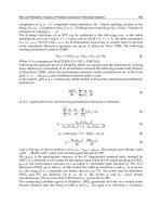
“moderately useful” and “very useful,” respectively. Table 1 shows system evaluation
result. Some comments for future improvements in the CBMEM system were also obtained
from the project participants.
The functionality of system Mean Score
Ease of acquiring experience 4.7
Reliability 4.3
Applicable to Construction Industry 4.8
The use of system Mean Score
Ease of Use 4.8
User Interface 4.5
Over System Usefulness 4.4
The capability of system Mean Score
Reduce Unnecessary time 4.6
Reduce Unnecessary Costs 4.4
Reduce Happening Mistake Percentage 4.6
Ease of finding related experience 4.7
Enhance Experience Updating Problems 4.3
Improve Experience Sharing Problems 4.4
Note: the mean score is calculated from respondents' feedback on
fivescale questionnaire: 1(Strongly Disagree), 2, 3, 4 and 5 (Strongly Agree)
Table 1. System Evaluation Result
The use of web technology and CAD-based Maps (CBM) to share and illustrate available
experience significantly enhanced the efficiency of experience management (EM) processes.
Based on the user satisfaction survey, most users agreed that the CBMEM system enables
engineers to exchange and share previous experience using CBM to express their ideas and
Developing Construction CAD-Based Experience Management System
97
thoughts. Furthermore, the CBM provided clear and dynamic representations of experience
and effectively identified CAD units with experience and knowledge related to the project.
The survey revealed a user satisfaction rate of 91 %, indicating that the CBMEM system is
useful for assisting engineers in editing their previous experience through the CBM
approach to enhance experience acquisition and management. The experimental results
showed that the CBMEM system significantly enhanced progress in the construction
experience exchange progress and management. Overall, the use of CBMEM system
minimized ineffective experience communication and exchange among engineers.
The significant findings of the case study are summarized as follows: (1) the total number of
experience units in the system was 1,437 experience units with 129 experience packages during
execution of the project; (2) most senior engineers and experts considered recording and editing
their experience to be too time consuming; (3) assisting more senior engineers in transferring
tacit experience can be problematic, because most senior engineers cannot type their experience
by themselves, and (4) most engineers agreed that the CBM approach and CBMEM system are
helpful to enabling experience sharing and management in construction projects.
9. Conclusions
This study proposed a novel and practical methodology for capturing and representing the
experience and project knowledge of engineers by utilizing a CAD-based Maps (CBM) approach.
Furthermore, this study developed a Construction Dynamic CAD-based Map Experience
Management (CBMEM) system for engineers which provides a dynamical experience exchange
and management service for the reuse of domain knowledge and experience. CBM divide
experience into map units, thus forming an effective experience management tool in construction
projects. Effective integration of web technology in CBMEM system has been demonstrated in
the case study in the Taiwan construction building project. The CBMEM system enables
engineers to exchange and share previous experience using CBM to express their ideas and
experience. Furthermore, the CBMEM system enables users to request experience support and to
exchange experience with selected engineers or all enterprise engineers by submitting problem
descriptions through CBM. Novice engineers directly accessing the system can effectively share
and exchange experience. The integration of experience management (EM) and the CBM
approach appears to be a promising means of enhancing construction EM during the
construction phase of a project. In summary, the CBMEM system can assist engineers in
illustrating their ideas clearly and sharing their experience. Furthermore, CBMEM system and
CBM approach enable users to survey and access effectively the tacit and explicit experience of
previous engineers and experts in similar projects.
Although further effort is needed to update the explicit/tacit experience related to various
projects, the proposed system benefits construction experience management by (1)
providing an effective and efficient web-based environment for exchanging experience
specifically regarding construction projects; and (2) providing users options by requesting
assistance from selected engineers or all engineers in the enterprise who have relevant
experience by submitting a problem description.
The use of the CBM approach in the system mainly provides assistance to help engineers
illustrate their own knowledge easily and effectively. The questionnaire results indicate that the
primary advantages of CBM in the system are as follows: (1) the CBM provide clear and
dynamic representations, thus identifying the experience and knowledge of engineers relevant
to the project, (2) the CBM clearly identify the available engineers or experience to request for
experience exchange regarding the special experience and knowledge in the current project and
(3) users can locate needed experience easily and effectively based on CBM illustration.
Robotics and Automation in Construction
98
10. References
Bergmann, Ralph (2002), Experience Management: Foundations, Development
Methodology, and Internet-Based Applications, Springer, Germany.
Buzan T. & Buzan B., (1993), The mind map book: How to use radiant thinking to maximize
your brain’s untapped potential, New York; Plume.
Davenport, T.H. and Prusak, L. (1998), Working Knowledge, Harvard Business School Press
Fong, P. S. W. and Chu, L. (2006), Exploratory study of knowledge sharing in contracting
companies: a sociotechnical perspective. Journal of Construction Engineering and
Management, 132(9), 928-939.
Fong, P. S. W., Hayles, C. S., and Hills, M. J. (2007), Dynamic knowledge creation through
value management teams. Journal of Management in Engineering, 23(1), 40-49.
Kamara, J.M., Augenbroe, G., Anumba, C.J., and Carrillo, P.M. (2002), Knowledge management in
the architecture, engineering and construction industry. Construction Innovation, 2, 53-67.
Liebowitz, J. (2005), Linking social network analysis with the analytic hierarchy process for
knowledge mapping in organizations, Journal of Knowledge Management, Vol. 9
No.1, 76-86.
Malhotra, Y. (2000), Knowledge management and virtual organizations. Idea Group
Publishing, Hershey, PA.
Malhotra, Y. (2001), Knowledge management and business model innovation. Idea Group
Publishing, Hershey, PA.
Manavazhi, M. R. (1995). “Case-based Reasoning and Hypermedia: Enabling Technologies
for Construction Experience Transfer.” Technical Report # 102, Center for
Integrated Facility Engineering, Stanford University, CA, August 1995.
McAleese, R. (1998), The knowledge arena as an extension the concept map: reflection in
action, Interactive Learning Environments, Vol. 6 No. 1, 1-22.
Noll, M., Frohlich, D. and Schiebel, E. (2002), Knowledge maps of knowledge management
tools: information visualization with BibTechMon, in Karagiannis, D. and Reimer,
U. (Eds), Practical Applications of Knowledge Management 2002 Conference
Proceedings, Springer-Verlag, New York, NY.
Reuss, Mark C. and Tatum, C. B. (1993). “Requirements and Tools for Transferring
Construction Experience between Projects.” Technical Report # 78, Center for
Integrated Facility Engineering, Stanford University, CA, Feb 1993.
Tatum, C. B. (1993). “Structure and Characteristics of Knowledge from Construction
Experience.” Technical Report # 81, Center for Integrated Facility Engineering,
Stanford University, CA, Feb 1993.
Tiwana, A. (2000), The knowledge Management Toolkit – practical techniques for building a
knowledge management system. Prentice-Hall, New Jersey.
Trochim, W.M. (1989), An Introduction concept mapping for planning and evaluation,
Evaluation and Program Planning, 12(1), 1-16.
Udaipurwala, A. and Russell, A.D. (2002), Computer-assisted construction methods knowledge
management and selection. Canadian Journal of Civil Engineering, 29(3), 499-516.
Wexler, M. (2001), The who, what, and why of knowledge mapping. Journal of knowledge
management, 5(3), 249-263.
Woo, Jeong-Han, Clayton, Mark J, Johnson, Robert E., Flores, Benito E., and Ellis,
Christopher (2004), Dynamic Knowledge Map: reusing experts’ tacit knowledge in
the AEC industry. Journal of Automation in Construction, 13(2), 203-207.
7
Applications of Computer Aided Design to
Evaluate the Zoning of Hazard Prevention in
Community Neighbours
Kuo-Chung Wen
Institute of Architecture and Urban Planning, Chinese Culture University
Taiwan, R.O.C.
1. Introduction
The city government will provide the enough emergence routes, parks, and so on to reduce
the hurtful accidents during the escape by making the urban plan. The proportions of the
Zoning of Hazard prevention will be influenced by some main policy such as the develop
directions, population and some effects, and sometimes get a poor proportions. So in this
study we want to use some methods such as spatial and Network Analysis to set up the
Zoning of Hazard prevention and estimate the safety of these area (Li, 1997).
So in this study we use Geographic Information System (GIS) to combine with the spatial
information, systematize, and escape behaviour theory to simulate the escape situations.
Spatial information talks about characteristic in community layout. Systematize talks about
the relationship of the open space. Escape behaviour theory talks about the actions of
evacuation people and simulate the escape path in the community escape path. We aimed at
the community neighbours for study area. At first, we assess the escape paths and establish
the relationship of the street space. Second, we set up the cell to interpret the spatial
environment. Third, we suppose some types of people to simulate the escape path
evacuation.
The theoretical basis of the research included Genetic Algorithms (GA). The biological
evolution aroused GA, which is a kind of optimization search model within natural choice
process. It operates by the way of the encoding gathered by parameter and gets rid of
restrictions of seeking space analysis. For this reason, we can get the Global Optimum faster,
and prevent it become the Local Optimum (Blanco, et al. 2000). Therefore, the study uses the
dynamic process of the genetic calculation, and goes on the choice of the evacuation path.
Receiving the batter population, we combine the function of the GIS Spatial Analysis (SA),
under the disaster prevention theories, it can simulate and present a more safe model of
Dynamic Path Choose Model (DPCM) that near to the behaviour of the really evacuation in
mankind.
The part of DPCM could be divided into four parts. (i), is to set the population of GA
operation. (ii), is to choose crossover and mutation. (iii), is to calculate the fitness function of
each generation and to select the better gene arrangement. (iv), is to reproduce, after
evolution, we can establish evacuation path that more reflect really human action and choice
when hazard takes place.
Robotics and Automation in Construction
100
Finally, we compare the NA with GA calculation, and Establish real model of DPCM to
choosing evacuation path. The results are three parts: 1, measure the safety of the
community neighbours. 2, simulate of escape path evacuation. 3, estimate the safety area of
community.
2. Theory
The theoretical basis of the research included GA, GIS, Network Analysis (NA) and disaster
prevention theories combine with the spatial information, systematize, and escape
behaviour theory to simulate the escape situations. Spatial information talks about
characteristic in urban area. Systematize explain the relationship of the street networks.
Escape behaviour theory talks about the actions of evacuation people and simulate the
escape path in the community escape path (Breaden, 1973). The biological evolution aroused
GA, which is a kind of optimization search model within natural choice processes. It
operates by the way of the encoding gathered by parameter and gets rid of restrictions of
seeking space analysis. For this reason, we can get the Global Optimum faster, and prevent
it become the Local Optimum. Therefore, the study uses the GA and NA to goes on the
choice of the dynamic flooding evacuation path. By the way, we can display the more real
human behaviour and find the least cost evacuation path by the dynamic program of the
data base in time. Receiving the batter population, we combine the function of the GIS
Spatial Analysis, under the disaster prevention theories, it can present a more safe model
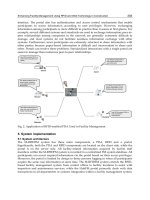
that near to the behaviour of the really evacuation in mankind. The structure of combined
GA with GIS is like Fig. 1.
OUT
Flood Data Bass
Flood Frequency
Urban Plan Data
Building Data
Traffic Network
Data
…
1. Different time series
flood situation
2. Traffic Node
Reproduction
Crossover
Mutation
No
NA
2D Flooding
Evacuation model
Yes
GIS GA
Comparative
Dynamic Evacuation
path choice
Disaster
Prevention
Theories
Fig. 1. The structure of combined GA with GIS
Applications of Computer Aided Design to Evaluate the Zoning of Hazard Prevention
in Community Neighbours
101
2.1 Disaster prevention systems
According to the level of disaster and place, the emergence shelter should proved the
functions like command post, information, disaster prevention, medical treatment, goods
saving and so on. So the setting of emergence shelter should choice the local government,
lodge to be the command post and the park, elementary school, community centre to be the
emergence shelter.
The planning of the emergence routes are depended on the different situation. The most
important function is to provide people to escape to the safety place. And according to the Taipei
Disaster-Prevention Planning, The roads were classified into emergency path system, rescue
transport path system, fire control path system, and assist path system (8m) (Tseng, 2000).
Zoning of hazard prevention is an independence area which is not be influence from next
area and when disaster occurred the people in the area dose not escape to other ones. And
the zoning area can accept enough people.
The walk speed will be closed to normal speed if there is enough space. On the contrary, if
there is not enough space, walk speed will be slow down even closed to stop depending on
the increasing density. Dr. Tanaboriboon and Dr. Guyano think about that walk speed and
body characteristics of western is differ with oriental. At the centre street of Bangkok city in
Thailand it was studied to survey location the ambulation of people (Tanaboriboon &
Guyano, 1989). They divide service level of ambulation into 6 rankings (A, B, C, D, E and F).
And they convert walk speed base on the relationship of density and discharge like Table 1.
Services
level
Density (Person /
Square metre)
Velocity (Metre
/Second)
Flow (Person /
Metre * Second)
Condition
A <=0.42 >=1.12 <=0.47
* Don't generate conflict each
other
B 0.43~0.63 1.06~1.11 0.48~0.67
* The velocity and flows
become slightly slow
C 0.64~1.02 1.00~1.05 0.68~1.02
* The pedestrian needs to
adjust the velocity and
directions
D 1.031~1.54 0.88~0.99 1.03~1.35
* Difficult to change the
direction and cross
E 1.55~2.70 0.62~0.87 1.36~1.68
* Extremely difficult to
change the direction and
cross
F >2.71 <0.61 >1.69
* Can't reverse direction and
cross
(Tanaboriboon & Guyano, 1989)
Table 1. The walking services level that Tanaboriboon and Dr. Guyano established
2.2 Dynamic programming
We can use dynamic programming to find the suitable evacuation path. With the dynamic
programming, we can establish the decide node in the time and the node of the traffic street
network. And we can combine the attribute of the traffic network and some important
information with GA to find the optimum Escape Path.
Robotics and Automation in Construction
102
2.3 Network analyze
Network Analyze is a way can get the optimum solution by some designate standards of the
traffic network database. Networks are making up with some information which are
expressing with points and lines. It is suitable to modelling roads, pipes, facilities and finds
the optimum answers. Network analysis is one kind of analysis which in depended on the
model of GIS system. The analysis way is to connect the spatial feature such as polygon, line
and point and calculate the type and characteristic with the connecting networks (Djokie &
Maidment, 1996).
ij
(, )
min z( ) C
ij
ij A
XX
∈
=
∑
(1)
A: The set of arc in street network
Xij: The flow of arc(i,j)
Cij: The cast of arc(i,j)
2.4 Genetic algorithms
John Holland proposed genetic algorithms (GA) in 1795. This is an optimization of problem
solving and technologic of machine learning. It is enlightenment from creature evolution
process. The answer of every problem expresses a chromosome that present an individual
creature. A group of creature were evolution by Darwin's evolutionism compete and select.
The fitting creature exists that present the good solution survival the bad eliminates through
competition. The new solution of new generation also to model creature propagates by
survival's individual copulation and mutation (Bullock, 1995).
There are four different points between GA and traditional way of optimization and search
(Woodbury 1993).
1. GA deals with whole set of solution, not only solution itself.
2. The search of GA starts from a group of population fitting well and scattering
beginning, not from a point.
3. GA is objective function, not differentiation or others assist knowledge.
4. GA leads the direction of search only by hands around rule of probability.
It is a series process of self adjusts in search control of design reasoning of GA (Jo & Gero,
1995). The combination of design reasoning rules could be a chromosome of one of
evacuation path solution. Every set of chromosome is whole result of inference path
generated by probability. These evolution from parents and generate next generation were
selected by environment conditions. Those are constantly adjusted through heuristic rules
and search strategy, stop until solution fit need. The whole process of evolution is the
process of finding out answer. The final result of inference paths, evaluative rules and
solution is important knowledge of evacuation path. There are three process follow:
1. Reproduction
The probability of copy from parents is derived from fitness degree of the chromosome.
The common method is Roulette Wheel Selection by the percentage of its fitness degree
of the chromosome over summarization of all fitness degree. That is the more high
fitness degree the more opportunity to duplicate from parents.
2. Crossover
After reproduction the crossover provide for exchange chromosomes between mother
generations in order to get the befitted chromosome from parents (Chan & Tansri,
1994).
Applications of Computer Aided Design to Evaluate the Zoning of Hazard Prevention
in Community Neighbours
103
3. Mutation
It may change some genes form some chromosomes to avoid lost the befit information
by reproduction and crossover in the genetic process. So we can extend the searching
space to escape from the local optimum to the global optimum.
3. Modelling
3.1 Establish the platform
This research carries on the construction of the development platform of the database with
the geographical information system. Collect and set up relevant databases at first, then
derive the model assessed in simulation and set up the data to export into interfaces. In
collection of the database, will mainly collect the urban planning map and relevant attribute
data, in order to build the basic geographical information system of database which
constructs the calamity area, to offer basic spatial analysis and application, but the digit
picture that this stage needs to finish, change of the scope of activities via presenting the
time array of this area after network analysis. So must turn attribute data and spatial data
into information forms of GIS, for systematic operation, it is mainly attribute data to move
the urban street network, the attribute data are with the basic graph: To spread out with
point ,line and polygon, each of spatial data all has specific codes and corresponding
attribute value, taking network layout of traffic way as an example, its attribute data
include: Serial number, length, driving speed, etc. the attribute data are stored in the data
form of attribute, elected fetching the data record When, figure when it is corresponding
choosing. Attribute data form and basic map is construct for escape simulation of flood
disaster to take special database, digital elevation model urban planning street map, floods
water possibilities map, traffic network data, etc.
We use GIS to establish the system which combining the data base of the flood information.
At first, we search and collect the flooding data base. And than we infer the estimating
model, and set up the in put and out put of the system. About the base data, we collect the
urban planning map and some correlating data to be the digital data. It can provide some
applications and display the variations of the activity of the time series in the area. We
divide the format into three parts, the data base are display in the shape of point, line and
polygon. There are its own coding and data in each spatial object. For example, the traffic
network has its own data just like coding, length, speed and so on. These data are written in
the table of the data base. When you select the record, the corresponding shape will be
selected. In this study, we establish these spatial data which are the topographic chart, the
data of traffic network, the block of urban planning, and the flood frequency, and so on to
model the evacuation path.
We study with the community neighbors. At first, we assess the Emergence route and
establish the relationship of the street space. Second, we set up the cell and street networks
to interpret the spatial environment. Third, we suppose some methods to simulate the
Zoning of Hazard prevention evacuation and to divide the different of the Zoning of
Hazard prevention (Li, 1999).
3.2 Establish the rescue refuge rings
3.2.1 Emergence shelter
After the basic data are collected, to city taking escape stronghold is it select to go on, as take
escape to choose stronghold mainly with school, park open space mainly here of the area.
Robotics and Automation in Construction
104
3.2.2 Emergence route
Planer will take escape in the route and divide into four grades mainly while urban
planning of the road value and to assess proceed of present situation, and classify the traffic
network, in order to use as the follow-up network analysis.
3.2.3 Zoning of hazard prevention
The escape area is divide four part to mainly to set up, the major is divide into spatial
geometry and network analysis two ways.
1. Spatial Geometry Analysis
With analysis and geometry of ring land that is regarded as the calculation that is
rowed and had in space geometry is analyses, analysis in accordance with making and
rowed and set up the space equidistantly, but several geometry analyses that separate
and take escape the area with the central line in the ring land.
2. Network Analysis
Network analysis is make mathematical calculations to go on with time and distance
two impedance, it is analysis to go on with unit length by each impedance value of
route to hinder to resist, regard place of making it as with school export when the it can
be regarded, in area can reached is it appear to go on so as to a data.
3.3 Establish the dynamic evacuation path model
3.3.1 Dynamic evacuation path
E0
E1 E2 E3 E4
E0
E1’ E2 E3
E0
E1’ E2’ E3 E4
E0
E1’ E2’ E3’ E4
Pb
Pa
P3
P4
E0
E1
P1
E0
E1 E2
P2
t0
t1 t2 t3 t4
S1
S2
S3
S4
Fig. 2. The dynamic evacuation path model
We establish the evacuation path by the data of different time series. We suppose that the
depth of the flood get an even rising. So we divide the time into some parts of time series.
Upon the data of the time series, we can get the flood frequency in the different time series
and help us to make some decision. In this study, we used different decision node in the
traffic network and different time series to select the evacuation path like Fig. 2. In Fig. 2, DP
is combined with S1, S2, S3 and S4, and according to the different data bases in each time
series these evacuation paths. E is the decision nodes of path.
The dynamic evacuation path is defined by
Applications of Computer Aided Design to Evaluate the Zoning of Hazard Prevention
in Community Neighbours
105
(
)
(
)
(
)
()
11 2 2
12
1
1
1
sd s d sndm
tt to
o
m
n
sndm
to
t
d
s
DP P P P
DP P
=
=
=
=+ ++
=
∑
(2)
d: the depth of the flood ; t: the time series;
p: the moving path; s: segment of path
DP: Path Distance.
We use Best Route (BR) to calculate the optimum in this study. BR is one kind of the
network analysis. It uses the minimum cumulative impedance to find the optimum with
two or more traffic nodes in the traffic network. These path nodes can be sequence. And the
response unite can be selected in the traffic network data items. For example, we can use the
distance and time as the response unites to simulating the more real situation. So we use
distance and deliver time to calculate the optimum in this study.
3.3.2 Genetic algorithms
The knowledge representation is the key of whole system of Evacuation Path Model (EPM).
There are chromosome, environmental parameters and fitness function. These derived from
path table, node table, choose table, dynamic function and GA table in GIS.
Method
Point
P1 P2 P3 P4 P5 P6 P7 P8 P9 P10 P11 P12 ….
0 0 0 0 0 0 0 0 0 0 0 0 0 …
1 P4 P1 P2 P1 P4 P5 P6 P10 P8 P8 P16 P4 …
2 P2 P3 P8 P5 P13 P2 P14 P9 P7 P13 …
3 P6 P12 P6 P7 P10 P3 P16 …
Table 2. Choose Table
1. Code of Chromosome
The concept is developed by initial evacuation path’s idea. The result of chosen path could
be transformed a serious genes to combine chromosome. Assuming one area has many
nodes (for example… P1, P2, P3, …, Pn.), each node has a lot of path to be chosen. The Fig. 3
shows the node P1 has two paths can be chosen, there are two chosen method. As the same
way, the P2 has three chosen method. Thus we can establish the attributes of choose table
(like table 2) from node table. The table 2 presents the spatial relationship and chosen
method of each node.
The dynamic function is to transform the gene code into the evacuation path (like Fig. 4).
The gene code follows the id to be a chromosome in the GA. The id just the sequence
number there is no any means in this table. If we decide the start node is (P1) and the end
node is (P14) of evacuation path. The first id just is in the name of start node (P1), the gene
code is (1). Then we can choose the next node by index the gene code from choose table. For
the start node (P1, 1) we can index P1 choose the (1) method to find out the P4. So the next
node is P4, we transform the gene code from (1, 1) to (P1, 1) to (P1, P4). Then repeat the steps
Robotics and Automation in Construction
106
above until the next node is just equal the end node. Final we can spatial join table to GIS to
draw out the evacuation path (like the red line in Fig. 4).
Fig. 3. The method of node choose
Fig. 4. The dynamic function to transform the gene code into the evacuation path
The rule of crossover between two chromosomes is before we cut any segment by random,
after we crossover them.
Before crossover PathA: 1,1,2,……,2,1 PathB: 1,1,4,……,2,1 (3)
After crossover PathA: 2,1,4,……,3,1 PathB: 2,1,2,……,3,1
2. Environmental Parameter
• DF: Degree of Fitness. The value was calculated by the fitness function. Then it transfers
each case’s subsistence probability. The function follows:
∑
=
=
n
j
jii
DFDFALIVE
1
/
(4)
DF: Degree of Fitness.
i: the i’th case
j=1 to n, n is the total cases
• PN: Population Number. The numbers of total individual, the max living numbers of
controlled environment
P1
P4
P12
P2
P5
P6
P3
P7
P10
P8
P9
P11
P13
P14
P15
P16
1
2
For P1 chose method 2: p4, p2
P1
P4
P12
P2
P5
P6
P3
P7
P10
P8
P9
P11
P13
P14
P15
P16
1
2
3
For P2 chose method 3: p1, p3, p6
123456789
1 2 3 3 2 0 0 0 0
123456789
2 2 2 1 3 3 1 0 0
決策
基因
決策
基因
ID
Gene
ID
Gene
P1
P4
P12
P2
P5
P6
P3
P7
P10
P8
P9
P11
P13
P14
P15
P16
Applications of Computer Aided Design to Evaluate the Zoning of Hazard Prevention
in Community Neighbours
107
• RR: Reproduction Rate is the copy rate of mother generation. Whether the individual
child will be reproduction, it depended on its subsistence probability. If the subsistence
probability is higher, it will be more chance copied. It will have more opportunity to
evolve.
• CR: Crossover Rate is the exchange percentage between any two chromosomes of parents.
• MR: Mutation Rate is self-change probability of any chromosome.
3. Fitness Function
The fitness function is the rules to estimate cases and give weight score. It is the tool to judge
the better or worse one. It can decide to eliminate the unsuitable case. It including evaluation
the rank of evacuation path, the successive nodes of evacuation path, the number of nodes, the
length of evacuation path and the number of repeat path in evacuation path choose.
4. Result
4.1 Computing rescue refuge rings in shiji area
This chapter will take the Shiji City in the Keelung River Basin for case in this study. The
boundary is like Fig. 5. We apply river digital topographic map, Digital Elevation Model,
Traffic Network Data, Urban Planning Map, etc. According the functions required. We can
analyze the demand of data, and build database.
Fig. 5. the urban plan of Shiji City
4.1.1 Emergence shelter setting
To define the boundary of Urban Disaster Prevention & Rescue Refuge Rings, we take the
service radius (600m) of high school elementary schools, and the range of refuge rings is
about 300m~500m. The walk time of refuge rings is about 5~10 minutes and to consider
other resource of Disaster Prevention & Rescue. The construction of the disaster prevention
network model is like Fig. 6.