Manufacturing the Future 2012 Part 8 pptx
Bạn đang xem bản rút gọn của tài liệu. Xem và tải ngay bản đầy đủ của tài liệu tại đây (1.73 MB, 50 trang )
Distributed Architecture for Intelligent Robotic Assembly, Part I: Design… 341
to their respective type and another problem of the event channel is that it
could saturate the network, since it does not have an event filter and sends all
messages to all clients. The event services does not contemplate the use of QoS
(Quality of Service), related with the priority, liability and order.
The third technique is based on the Notification Service of CORBA. It is an im-
provement of the Service of Events. The most important improvement in-
cludes the use of QoS. In the notification service each client uses the events in
which it is interested.
The implementation of the Callback technique offers a better performance than
the others; however the ones based on the event channel are easily scalable.
The technique used in our research is Callback since the number of clients, is
not bigger of 50.
In (Amoretti, 2004) it is proposed a robotic system using CORBA as communi-
cation architecture and it is determined several new classes of telerobotic ap-
plications, such as virtual laboratories, remote maintenance, etc. which leads to
the distributed computation and the increase of new developments like
teleoperation of robots. They used a distributed architecture supporting a large
number of clients, written in C++ and using CORBA TAO as middleware, but
it is an open architecture, and it does not have intelligence, just remote execu-
tion of simple tasks.
In (Bottazzi et al., 2002), it is described a software development of a distributed
robotic system, using CORBA as middleware. The system permits the devel-
opment of Client-Server application with multi thread supporting concurrent
actions. The system is implemented in a laboratory using a manipulator robot
and two cameras, commanded by several users. It was developed in C++ and
using TAO.
In (Dalton et al., 2002), several middleware are analyzed, CORMA, RMI (Re-
mote Method Invocation) and MOM (Message Oriented Middleware). But
they created their own protocol based on MOM for controlling a robot using
Internet.
In (Jia et al., 2002), (Jia et al., 2003) it is proposed a distributed robotic system
for telecare using CORBA as communication architecture. They implemented
three servers written in C++, the first one controls a mobile robot, the second
one is used to control an industrial robot and the last one to send real time
video to the clients. On the other side of the communication, it is used a client
based on Web technology using Java Applets to make easier the use of the sys-
tem in Internet. In (Jia et al., 2003), the authors increased the number of servers
Manufacturing the Future: Concepts, Technologies & Visions
342
available in the system, with: a user administrator and a server for global posi-
tioning on the working area.
In (Corona-Castuera & Lopez-Juarez, 2004) it is discussed how industrial ro-
bots are limited in terms of a general language programming that allows learn-
ing and knowledge acquisition, which is probably, one of the reasons for their
reduced use in the industry. The inclusion of sensorial capabilities for autono-
mous operation, learning and skill acquisition is recognized. The authors pre-
sent an analysis of different models of Artificial Neuronal Networks (ANN) to
determine their suitability for robotic assembly operations. The FuzzyART-
MAP ANN presented a very fast response and incremental learning to be im-
plemented in the robotic assembly system. The vision system requires robust-
ness and higher speed in the image processing since it has to perceive and
detect images as fast as or even faster than the human vision system. This re-
quirement has prompted some research to develop systems similar to the
morphology of the biological system of the human being, and some examples
of those systems, can be found in (Peña-Cabrera & Lopez-Juarez, 2006), (Peña-
Cabrera et al., 2005), where they describe a methodology for recognising ob-
jects based on the Fuzzy ARTMAP neural network.
2.2 Multimodal Neural Network
A common problem in working in multimodality for robots systems is the em-
ployment of data fusion or sensor fusion techniques (Martens, S. & Gaudiano,
P., 1998 and Thorpe, J. & Mc Eliece, R., 2002). Multimodal pattern recognition
is presented in (Yang, S. & Chang, K.C., 1998) using Multi-Layer Perceptron
(MLP). The ART family is considered to be an adequate option, due to its su-
perior performance found over other neural network architectures (Carpenter,
G.A. et al., 1992). The adaptive resonance theory has provided ARTMAP-FTR
(Carpenter, G.A. & Streilein, W.W, 1998), MART (Fernandez-Delgado, M &
Barro Amereiro, S, 1998), and Fusion ARTMAP (Asfour, et al., 1993) —among
others— to solve problems involving inputs from multiple channels. Nowa-
days, G.A. Carpenter has continued extending ART family to be employed in
information fusion and data mining among other applications (Parsons, O. &
Carpenter, G.A, 2003).
The Mechatronics and Intelligent Manufacturing Systems Research Group
(MIMSRG) at CIATEQ performs applied research in intelligent robotics, con-
cretely in the implementation of machine learning algorithms applied to as-
Distributed Architecture for Intelligent Robotic Assembly, Part I: Design… 343
sembly tasks —using distributed systems contact forces and invariant object
recognition. The group has obtained adequate results in both sensorial modali-
ties (tactile and visual) in conjunction with voice recognition, and continues
working in their integration within an intelligent manufacturing cell. In order
to integrate other sensorial modalities into the assembly robotic system, an
ART-Based multimodal neural architecture was created.
3. Design of the Distributed System
3.1 CORBA specification and terminology
The CORBA specification (Henning, 2002), (OMG, 2000) is developed by the
OMG (Object Management Group), where it is specified a set of flexible ab-
stractions and specific necessary services to give a solution to a problem asso-
ciated to a distributed environment. The independence of CORBA for the pro-
gramming language, the operating system and the network protocols, makes it
suitable for the development of new application and for its integration into
distributed systems already developed.
It is necessary to understand the CORBA terminology, which is listed below:
A CORBA object is a virtual entity, found by an ORB (Object Request Bro
ker, which is an ID string for each server) and it accepts
petitions from the clients.
A destine object in the context of a CORBA petition, it is the CORBA ob
ject to which the petition is made.
A client is an entity which makes a petition to a CORBA object.
A server is an application in which one or more CORBA objects
run.
A petition is an operation invocation to a CORBA object, made by a
client.
An object reference is a program used for identification, localization and di
rection assignment of a CORBA object.
A server is an identity of the programming language that imple
ments one or more CORBA objects.
The petitions are showed in the figure 2: it is created by the client, goes
through the ORB and arrives to the server application.
Manufacturing the Future: Concepts, Technologies & Visions
344
C lie n t A p p lic atio n
C lient O R B N ucleu s
DII
Static
Stub
ORB
Interface
Server A pplication
Server O R B N u cleu s
Skeleton
O bject
Adapter
ORB
Interface
DSI
N etw ork
ID L D e
p
en dent
The sam e for any application
Several o bject adapters
Figure 2. Common Object Request Broker Architecture ( COBRA)
• The client makes the petitions using static stub or using DII (Dynamic
Invocation Interface). In any case the client sends its petitions to the
ORB nucleus linked with its processes.
• The ORB of the client transmits its petitions to the ORB linked with a
server application.
• The ORB of the server redirect the petition to the object adapter just
created, to the final object.
• The object adapter directs its petition to the server which is imple-
mented in the final object. Both the client and the sever, can use static
skeletons or the DSI (Dynamic Skeleton Interface)
• The server sends the answer to the client application.
In order to make a petition and to get an answer, it is necessary to have the
next CORBA components:
Interface Definition Language (IDL): It defines the interfaces among the pro-
grams and is independent of the programming language.
Language Mapping: it specifies how to translate the IDL to the different pro
gramming languages.
Object Adapter: it is an object that makes transparent calling to other ob
jects.
Protocol Inter-ORB: it is an architecture used for the interoperability among
different ORBs.
The characteristics of the petitions invocation are: transparency in localization,
transparency of the server, language independence, implementation, architec-
ture, operating system, protocol and transport protocol. (Henning, 2002).
Distributed Architecture for Intelligent Robotic Assembly, Part I: Design… 345
3.1 Architecture and Tools
The aim of having a coordinator, is to generate a high level central task con-
troller which uses its available senses (vision and tactile) to make decisions,
acquiring the data on real time and distributing the tasks for the assembly task
operation.
Figure 3. Distributed Manufacturing Cell
Figure 3 shows the configuration of the network and the main components of
the distributed cell, however, the active ones are: SIRIO, SIEM, SICT and
SPLN. The system works using a multiple technology architecture where dif-
ferent operating systems, middleware, programming language and graphics
tools were used, as it can be seen in figure 4. It describes the main modules of
the manufacturing cell SIEM, SIRIO, SICT and SPLN.
Manufacturing the Future: Concepts, Technologies & Visions
346
Windows 2000 Windows 98 Linux Fedora Core 3 Linux Fedora Core 3
OmniORB
OmniORB ORBit ORBit
C++
C++ C C
Visual C++ Visual C++ GT
K
====
SIEM
SIRIO
SICT
SPLN
SO
Middleware
La
n
g
ua
g
e
Gra
p
hics
Figure 4. Different operating systems, middleware, programming languages and
graphic tools.
The architecture of the distributed system uses a Client/Server in each module.
Figure 5 shows the relationship client-server in SICT for each module. But with
the current configuration, it is possible a relationship from any server to any
client, since they share the same network. It is only necessary to know the
name of the server and obtain the IOR (Interoperable Object Reference).
SICT
CLIENT SERVER
SIEM
CLIENT
SERVER
SIRIO
CLIENT
SERVER
SPLN
CLIENT
SERVER
Figure 5. Client/server architecture of the distributed cell
The interfaces or IDL components needed to establish the relations among the
modules SICT, SIRIO, SIEM and SPLN are described in the following section.
Distributed Architecture for Intelligent Robotic Assembly, Part I: Design… 347
4. Servers Description
4.1 SICT Interface
This module coordinates the execution of task in the servers (this is the main
coordinator). It is base in Linux Fedora Core 3, in a Dell Workstation and writ-
ten in C language using gcc and ORBit 2.0. For the user interaction of these
modules it was made a graphic interface using GTK libraries.
The figure 6 shows the most important functions of the IDL.
<<Interface>>
SICT IDL
+ EndSIRIO(in finalStatus: long(idl)): void
+ EndSIEM(in finalStatus: long(idl)): void
+ EndSPLN(in finalStatus:
+ ExecuteSPLNCommand(in command: long(idl), in parameters: string(idl)): void
+ GetStatus(): CurrentStatus
…
<<Struct>>
CurrentStatus
+ description: string (idl)
+ error: long(idl)
+ eSirio: long(idl)
+ eSiem: long(idl)
+ eS
p
ln: lon
g
(
idl
)
Figure 6. SICT Interface
iSICT: the functions of this interface are used for SIRIO and SIEM to indicate
that they have finished a process. Each system sends to SICT a finished process
acknowledgement of and the data that they obtain. SICT makes the decisions
about the general process. The module SPLN uses one of the functions of SICT
to ask it to do a task, sending the execution command with parameters. The
figure 7 shows the main screens of the coordinator.
Manufacturing the Future: Concepts, Technologies & Visions
348
Figure 7. Controls of the interface SICT
Distributed Architecture for Intelligent Robotic Assembly, Part I: Design… 349
4.2 SIRIO Interface
This system is the vision sense of the robot, using a camera Pulnix TM6710,
which can move around the cell processing the images in real time. SIRIO car-
ries out a process based on different marks. It calculates different parameters
of the working pieces, such as orientation, shape of the piece, etc. This system
uses Windows 98 and is written in Visual C++ 6.0 with OmniORB as middle-
ware.
<<Interface>>
SIRIO IDL
+ StartZone(in numZone: long(idl)): void
+ GetCurrentStatus(): SirioStatus
+ GetDataPiece(): pieceZone
+ GetImage(): imageCamera
+ MovePositioningSystem(in command: long(idl), in x: long(idl), in y: long(idl), in vel: long(idl)):void
+ GetRealPositionPS(): realPosition
+ GetCFD(): CFD
…
<<Struct>>
piezeZone
+ x: double(idl)
+ y: double(idl)
+ Angle: double(idl)
<<Struct>>
realPosition
+ positionX: long(idl)
+ positionX: long(idl)
<<Struct>>
SirioStatus
+ activeCamera: Boolean(idl)
+ activePS: Boolean(idl)
+ errorDescription : string(idl)
<<Struct>>
imageCamera
+ dx: long(idl)
+ dy: long(idl)
+ im: octet(idl) [153600]
<<Struct>>
CFD
+ distant: double(idl)[180]
+ cenX: double(idl)
+ cenY: double(idl)
+ orient: double(idl)
+ z: double(idl)
+ cenX: double(idl)
+ id: b
y
te
(
idl
)
Figure 8. SIRIO Interface
iSIRIO interface contains functions used by the SICT to initialize the assembly
cycle, to obtain the status of SIRIO, an image in real time or to move the cam-
era over the manufacturing cell. The function StartZone, calls a process located
in SIRIO to make the positioning system move to different zones of the cell.
The function GetCurrentStatus is used to get the current status of the SIRIO
Manufacturing the Future: Concepts, Technologies & Visions
350
module, and it sends information about the hardware. When SIRIO finishes
processing an image it sends an acknowledgement to SICT and this ask for the
data using the function GetDataPiece which gives the position and orientation
of the piece that the robot has to assembly.
The function GetImage gives a vector containing the current frame of the cam-
era and its size. The function MovePositioningSystem is used by SICT to indi-
cate to SIRIO where it has to move the camera. The movements are showed in
table 1, where it executes movements using the variables given by the client
that called the function.
Tabla 1.
Command
Tabla 2. X Tabla 3. Y Tabla 4 Speed
Tabla 5. Start Tabla 6. No Tabla 7. No Tabla 8. Yes
Tabla 9. Zone 1 Tabla 10. No Tabla 11. Tabla 12. Yes
Tabla 13 Zone 2 Tabla 14. No Tabla 15. No Tabla 16. Yes
Tabla 17 Moves
to (x,y)
Tabla 18. Yes Tabla 19. Yes Tabla 20. Yes
Table 1. Commands for moving the positioning system.
The function GetRealPositonPS obtains the position (x, y) where the position-
ing system is located.
Figure 9. SIRIO main scream
Distributed Architecture for Intelligent Robotic Assembly, Part I: Design… 351
The last function GetCFD(), gets the CFD (Current Frame Descriptor) of a
piece. The piece is always the last the system used, or the one being used. The
CFD contains the description of a piece. For more details the reader is referred
to part III of this work (Peña-Cabrera, M. & Lopez-Juarez, I, 2006).
4.3 SIEM Interface
This contact force sensing system resembles the tactile sense, and uses a JR3
Force/Torque (F/M) sensor interacting with the robot and obtaining contact in-
formation from the environment. SIEM is used when the robot takes a piece
from the conveyor belt or when or when an assembly is made. The robot
makes the assemblies with incremental movements and in each movement,
SIEM processes and classifies the contact forces around the sensor, using the
neural network to obtain the next direction movement towards the assembly.
SIEM is implemented in an industrial parallel computer using Windows 2000
and written in Visual C++ 6.0 and OmniORB.
Figure 10 shows the main functions of the IDL SIEM.
<<Interface>>
SIEM IDL
+ MoveRobot(in numZone: long(idl), in Data: pieceZone): void
+ GetCurrentStatus(): SiemStatus
+ GetCurrentForces(): forcesReading
+ RobotMoveCommand(in command: long(idl), in DeltaX: long(idl), in DeltaY: long(idl), in Speed: long(idl), in Distance : long(idl)
…
<<Struct>>
piezeZone
+ x: double(idl)
+ y: double(idl)
+ Angle: double(idl)
<<Struct>>
forcesReading
+ vector: double(idl) [6]
+ Flimit: double(idl)
+ Mlimit: double(idl)
<<Struct>>
siemStatus
+ activeRobot: double(idl)
+ activeSensorFT: long(idl)
+ description: string(idl)
Figure 10. SIEM Interface
iSIEM: SICT moves the robot thought SIEM, obtains the components state and
the reading of the current forces in the different zones of the manufacturing
cell. The function GetCurrentStatus, is used to obtain the status of the hard-
Manufacturing the Future: Concepts, Technologies & Visions
352
ware (sensor F/T and communication) and software of the SIEM. The function
MoveRobot is used when SIRIO finishes an image processing and sends in-
formation about the piece to the task coordinator.
The GetCurrentForces function helps the SICT to acquire force data from the
JR3 Force/Torque (F/T) sensor at a selected sampling rate. This function returns
a data vector with information about the force and torque around X, Y and Z
axis.
Finally, the function RobotMoveCommand is used by the SICT to indicate ap-
propriate motion commands to SIEM. These types of motions are shown in
Table 2. Here is also shown the required information for each command (dis-
tance, speed). The windows dialog is shown in Figure 11.
Command Distance Speed
Command Distance Speed
Do nothing [static] No No Diagonal X+Y- Yes Yes
Home position No No Diagonal X-Y+ Yes Yes
Coordinates world No No Diagonal X-Y- Yes Yes
Tool Coordinates No No Finish Communica-
tion
No No
Axe by Axe Coordi-
nates
No No Open griper No No
Base Coordinates No No Close griper No No
Movement X+ Yes Yes Rotation A1+ Yes Yes
Movement X- Yes Yes Rotation A1- Yes Yes
Movement Y+ Yes Yes Rotation A2+ Yes Yes
Movement Y- Yes Yes Rotation A2- Yes Yes
Movement Z+ Yes Yes Rotation A3+ Yes Yes
Movement Z- Yes Yes Rotation A3- Yes Yes
Rotation X+ Yes Yes Rotation A4+ Yes Yes
Rotation X- Yes Yes Rotation A4- Yes Yes
Rotation Y+ Yes Yes Rotation A5+ Yes Yes
Rotation Y- Yes Yes Rotation A5- Yes Yes
Rotation Z+ Yes Yes Rotation A6+ Yes Yes
Rotation Z- Yes Yes Rotation A6- Yes Yes
Diagonal X+Y+ Yes Yes
Table 2. Commands to move the robot
Distributed Architecture for Intelligent Robotic Assembly, Part I: Design… 353
Figure 11. SIEM screen
4.4 SPLN Interface
The system provides a user interface to receive directions in natural language
using natural language processing and context free grammars. After the in-
struction is given, a code is generated to execute the ordered sentences to the
assembly system. The SPLN is based on Linux Fedora Core 3 operating system
using a PC and programmed in C language and a g++, Flex, Yacc and ORBit
2.0. compiler.
iSPLN: This interface receives the command status from the SPLN, and gets
the system’s state as it is illustrated in Figure 12.
EndedTask is used by the SICT to indicate the end of a command to the SPLN
like the assembly task. As a parameter, SICT sends to SPLN the ending of the
task. GetStatus function serves to obtain the general state of the SPLN.
Manufacturing the Future: Concepts, Technologies & Visions
354
<<Interface>>
SPLN IDL
+ EndedTask(in finalStatus): void
+ GetStatus(): splnStatus
…
<<Struct>>
splnStatus
+ description: string (idl)
+ error: long(idl)
Figure 12. Interface SPLIN
5. Multimodal Architecture.
We have described so far the architecture of the distributed system, where
each module has its own FuzzyARTMAP neural network, its own KB (Knowl-
edge Base) and configuration. The architecture showed in figure 13 shows the
current architecture module M
2ARTMAP. Currently, there is a coordinator
substituting the Integrator and Predictor in the upper level. M2ARTMAP has
demonstrated to be faster in training and learning than a single Fuzzy
ARTMAP making a fusion of all senses at the same time, for more details see
(Lopez-Juarez et al., 2005).
– Predictor is the final prediction component that uses modalities’
predictions.
– Modality is the primary prediction component that is composed
by an artificial neural network (ANN), an input element
(Sensor), a configuration element (CF), and a knowledge
base (KB).
Distributed Architecture for Intelligent Robotic Assembly, Part I: Design… 355
– Integrator is the component that merges the modalities’ predictions
by inhibiting those that are not relevant to the global
prediction activity, or stimulating those who are consid
ered of higher reliability —in order to facilitate the Pre
dictor’s process.
Predictor
(Fuzzy ARTMAP)
Integrator (rule-based)
ANN
(Fuzzy
ARTMAP)
Sensor
KB
CF
Modality i
En viromentE
i
⊆∈e
ANN
(Fuzzy
ARTMAP)
Sensor
KB
CF
Modality j
Envi romentE
j
⊆∈e
Figure 13. Multimodal neural architecture, M2ARTMAP, integrated by three main
components organized in two layers: Modality (several found at the lower layer),
Predictor and Integrator (at the upper layer)
Manufacturing the Future: Concepts, Technologies & Visions
356
5.1 Multimodal simulations
Fuzzy ARTMAP and M2ARTMAP systems were simulated using the Quadru-
ped Mammal database (Ginnari, J.H.; et al., 1992) which represents four mam-
mals (dog, cat, giraffe, and horse) in terms of eight components (head, tail, four
legs, torso, and neck). Each component is described by nine attributes (three
location variables, three orientation variables, height, radius, and texture), for a
total of 72 attributes. Each attribute is modelled as a Gaussian process with
mean and variance dependent on the mammal and component (e.g. the radius
of a horse’s neck is modelled by a different Gaussian from that of a dog’s neck
or a horse’s tail). At this point, it is important to mention that Quadruped
Mammal database is indeed a structured quadruped mammal instances gen-
erator that requires the following information to work: animals <seed> <# of
objects>.
Global performance
0.0
100.0
200.0
300.0
400.0
500.0
600.0
700.0
800.0
900.0
12345678
Quantity of Modalities
Average time (ms)
FuzzyARTMAP
M2ARTMAP
Linear (FuzzyARTMAP)
Linear (M2ARTMAP)
Figure 14. Performance comparison of Fuzzy ARTMAP vs. M2ARTMAP. (a) Training
phase. (b) Testing phase. (C) Global performance
In the first set of simulations, both Fuzzy ARTMAP and M2ARTMAP where
trained (in one epoch) and tested with the same set of 1000 exemplars pro-
duced with seed = 1278. Both architectures achieved 100% prediction rates.
Distributed Architecture for Intelligent Robotic Assembly, Part I: Design… 357
In the next set of simulations, Fuzzy ARTMAP and M2ARTMAP where ap-
plied to a group of 384 subjects (91 variations of the choice parameter and 4
variations of the base vigilance), both architectures where trained (again in one
epoch) using the set of 1000 exemplars produced with seed = 1278 and tested
using the set of 1000 exemplars produced with seed = 23941. Once again, both
achieved 100% prediction rates. Nevertheless, M2ARTMAP’s recognition rates
where slower than expected. Thus, a t-Student paired test was conducted to
constraint the difference between both architectures. It was confirmed that
M2ARTMAP’s recognition rate was at most 5% slower than Fuzzy ARTMAP’s
recognition rate, by rejecting the null hypothesis with a 1-tail p-value less than
0.0001.
The global performance of the M2ARTMAP indicated that its performance it is
superior when three or less modalities are used, which was considered accept-
able since in a manufacturing environment is likely to encounter two or three
modalities at most. The global comparison between M2ARTMAP and the Fuz-
zyARTMAP architecture is illustrated in Figure 14. (The reader is referred to
(Lopez-Juarez, I. & Ordaz-Hernandez, 2005) for complete details).
6. Results from the implementation of the Distributed System.
6.1 General Description
36 robotic assembly cycles were performed. Three modules were involved in
the assessment SICT, SIRIO and SIEM. At the start of the operation SICT indi-
cates to SIRIO to initialise the image processing in Zone 1, which corresponds
to the area where the male component is grasped from the belt conveyor. Later
this information is being sent to the SIEM which in turns moves the robot ma-
nipulator to pick up the component. At the same time the camera moves on
the working space detecting the Zone 2, where the fixed, female component is
located. This information is also sent to the SIRIO, to direct the robot towards
the assembly point. Once the part is grasped and in contact with the female
component the assembly operation is solely directed by the SIEM.
Table 3 contains the results from the 36 assembly cycles. The table provides in-
formation about the geometry of the component, chamfer, operation time, po-
sition error, based on the centroid location and the component rotation and fi-
nally the predicted type of assembly by the SIRIO module.
Manufacturing the Future: Concepts, Technologies & Visions
358
Test for grasping the parts was made from zone 1 for each geometry. Each
type was placed three times in the zone with 10º orientation difference and
four different locations.
In the assembly zone (zone 2) the location and orientation of the female com-
ponent was constant. However, this information was never available to the
SIEM or robot controller. So, every time this distance had to be calculated.
The first 18 assembly cycles were performed with chamfered female compo-
nents and the remaining 18, without a chamfer. This can be observed in Table
3.
The total time corresponds to the assembly cycle, including insertion time,
camera positioning, robot motion, image processing and home positioning. It
is important to mention that all speeds were carefully chosen since it was a
testing session. The system was later improved to work faster as it can be seen
in (Corona-Castuera & Lopez-Juarez, 2006). In this case for the assembly zone,
there was always an initial error, to test the error recovery.
ZONE 1 Error Zone 1 ZONE 2 Error Zone 2 # Piece Ch Time
(Min)
Xmm Ymm RZº Xmm Ymm RZº Xmm Ymm Xmm Ymm
Clasific.
1 square Yes 1,14 57,6 143,1 0° 2,4 1,9 0 82,8 102,0 0,3 1,8 square
2 square Yes 1,19 56,6 44,8 12° 15,2 0,2 2 82,8 101,1 0,2 1,2 square
3 square Yes 1,13 172,8 46,7 23° 2,20 -1,7 3 83,8 162,0 -0,9 2,1 square
4 rad Yes 1,72 176,7 145,1 29° -1,70 -0,1 -1 79,6 103,0 3,9 2,9 rad
5 rad Yes 1,86 56,6 143,1 36° 3,4 1,9 -4 82,8 103,0 0,6 2,9 rad
6 rad Yes 1,29 58,5 44,8 55° 15,2 0,2 5 80,7 102,0 1,5 2,3 rad
7 circle Yes 1,12 172,8 46,7 57° 2,20 -1,7 -3 82,8 101,1 0,4 1,2 circle
8 circle Yes 1,13 176,7 145,1 104° -1,70 -0,1 34 83,8 103,0 0 3 circle
9 circle Yes 1,24 56,6 143,1 79° 3,4 1,9 -1 79,6 102,0 3,2 2,2 circle
10 square Yes 1,7 56,6 42,8 66° 17,2 2,2 -24 79,6 102,0 3,5 1,9 square
11 square Yes 1,22 172,8 45,7 123° 2,20 -0,7 23 83,8 102,0 -2 2,4 square
12 square Yes 1,93 178,7 144,1 110° -3,70 0,9 0 80,7 102,0 0 0 square
13 rad Yes 1,79 55,6 143,1 116° 4,4 1,9 -4 82,8 102,0 1 2,4 rad
14 rad Yes 1,83 59,5 43,8 124° 16,2 1,2 -6 80,7 103,0 -0,5 2,3 rad
15 rad Yes 1,85 174,7 44,8 145° 0,30 0,2 5 82,8 102,0 1,8 3,1 square
16 circle Yes 1,76 176,7 147 143° -1,70 -2 -7 80,7 102,0 -0,4 2,2 circle
17 circle Yes 1,21 57,6 144,1 164° 2,4 0,9 4 82,8 102,0 2,2 2,4 circle
18 circle Yes 1,23 60,5 45,7 175° 14,3 -0,7 5 83,8 103,0 -0,3 2,4 circle
19 square No 1,21 174,7 48,6 0° 0,30 -3,6 0 81,7 103,0 -0,7 3,3 square
20 square No 1,13 177,7 147 12° -2,70 -2 2 82,8 103,0 0,5 1 square
21 square No 1,8 57,6 142,1 15° 2,4 2,9 -5 83,8 102,0 -0,5 0,8 square
22 rad No 1,84 61,5 45,7 26° 14,3 -0,7 -4 83,8 148,0 -1,6 -0,2 rad
23 rad No 1,26 175,7 49,6 36° -0,70 -4,6 -4 82,8 103,0 -2,7 0,2 rad
24 rad
No
1,21 179,6 147 49° -4,60 -2 -1 82,8 103,0 -1,7 1,3 rad
25 circle No 1,13 59,5 147 63° 0,5 -2 3 82,8 102,0 -1,1 0,9 circle
26 circle No 1,2 61,5 46,7 84° 13,3 -1,7 14 79,6 102,0 -1,7 0,2 circle
27 circle No 1,11 176,7 49,6 77° -1,70 -4,6 -3 82,8 102,0 1,2 0,5 circle
28 square No 1,71 178,7 148 71° -3,70 -3 -19 81,7 103,0 -1,7 0,1 square
29 square No 1,71 56,6 143,1 108° 3,4 1,9 8 79,6 103,0 0,6 0,9 square
30 square No 1,25 59,5 42,8 105° 17,2 2,2 -5 83,8 102,0 13,2 -9,3 square
31 rad No 1,71 174,7 46,7 116° 0,30 -1,7 -4 82,8 102,0 2,6 1,1 rad
32 rad
No
2,88 176,7 146 131° -1,70 -1 1 82,8 102,0 -2,1 0,1 rad
33 rad
No
1,82 57,6 143,1 131° 2,4 1,9 -9 82,8 102,0 -1,8 0,3 rad
34 circle No 1,28 58,5 43,8 145° 16,2 1,2 -5 78,5 103,0 -1,8 0,3 circle
Distributed Architecture for Intelligent Robotic Assembly, Part I: Design… 359
ZONE 1 Error Zone 1 ZONE 2 Error Zone 2 # Piece Ch Time
(Min)
Xmm Ymm RZº Xmm Ymm RZº Xmm Ymm Xmm Ymm
Clasific.
35 circle No 1,14 174,7 46,7 164° 0,30 -1,7 4 82,8 102,0 -2,8 0,3 circle
36 circle
No
1,16 176,7 146 170° -1,70 -1 0 82,8 102,0 2,7 1,2 circle
Table 3. Information of 36 assembly cycles for testing, with controlled speed
6.2 Time in Information transfers
During the testing session, different representative time transference was
measured. This was accomplished using time counters located at the begin-
ning and at the end of each process.
In the following graphs the 36 results are described . In Figure 15 a graph as-
sembly vs time is shown. In the graph the timing between the data transfer be-
tween the imageCamera data to the iSIRIO it is shown. From bottom up, the
first graph shows the timing SIRIO took to transfer the information in a matrix
form; the following graph represents timing between the transfers of image in-
formation. The following graph shows the time the client SICT used to locate
the image information to the visual component. Finally, the upper graph
shows the total time for image transfer considering all the above aspects.
0
100
200
300
400
500
600
700
1 3 5 7 9 11 13 15 17 19 21 23 25 27 29 31 33 35
Assemblies
Time (ms)
Server processing
Communication
Client processing
Total time
Figure 15. Transference of the information in the structure imageCamera of the SIRIO
interface
Figure 16 shows the graphs corresponding to timing of the 36 operations for
the transmission of pieceZone data type from the iSirio interface. The first
graph from bottom up show the time that the Server took to locate the infor-
Manufacturing the Future: Concepts, Technologies & Visions
360
mation in the structure pieceZone, the second graph shows the communication
time and finally the total operation time.
0
0.5
1
1.5
2
2.5
3
3.5
4
4.5
5
1 3 5 7 9 11131517192123252729313335
Assemblies
Time (ms)
Server processing
Communication
Total Time
Figure 16. Transference of the information in the structure pieceZone of the SIRIO in-
terface
Figure 17 shows the transference time of the sirioStatus data in the iSIRIO in-
terface, where the first graph from bottom up represents the information trans-
ference time, the second graph represents the SIRIO processing time verify the
camera status and the camera positioning system and finally the graph that
represents the sum of both. It is important to mention that the timing is af-
fected by the Server processing due to the process to verify the location of the
positioning system.
0
200
400
600
800
1000
1200
1400
1600
1800
1 3 5 7 9 11131517192123252729313335
Assemblies
Time (ms)
Communication
Total time
Server processing
Figure 17. Transference of information in the structure sirioStatus of the SIRIO inter-
face
Distributed Architecture for Intelligent Robotic Assembly, Part I: Design… 361
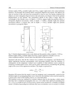
Finally, figure 18 shows the transference time from the F/T vector through the
forcesReading data type from the interface iSIEM. The first graph from bottom
up represents the communication times, the second, the time the SICT client
took to show the information in visual components. The upper graph repre-
sents the time SIEM Server took to read the sensor information and finally a
graph that represents the total time for each transference.
0
10
20
30
40
50
60
70
80
90
100
1 3 5 7 9 11 13 15 17 19 21 23 25 27 29 31 33 35
Assemblies
Time (ms)
Communication
Client processing
Server processing
Total time
Figure 18. Transference of information in the structure forcesReading of the SIEM in-
terface
6.3 Failure Measurement
We observed this point to statistically obtain the reliability of our system ac-
cording to the performance of our system. In the 36 assemblies carried out, (18
chamfered and 18 chamferless), we obtained a 100% success, in spite of the va-
riety of the intercommunications and operations of the modules. During the 36
assembly cycles we did not register any event which caused the cycle to abort.
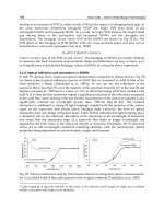
6.4 Robot Trajectories in the Assembly Zone
A robot trajectory describes the movements that the robot developed in the X,
Y and Rz directions starting from an offset error to the insertion point. In Fig-
ure 19 the followed trajectories for the first 18 insertions during circular cham-
fered insertion are shown whereas in Figure 20 the corresponding trajectories
for circular chamfered insertion are illustrated. In both cases a random offset
was initially given.
Manufacturing the Future: Concepts, Technologies & Visions
362
-40
-30
-20
-10
0
10
20
30
40
-40-30-20-100 10203040
Error X (mm/10)
Error Y (mm/10)
En 1
En 2
En 3
En 4
En 5
En 6
En 7
En 8
En 9
En 11
En 12
En 13
En 14
En 15
En 10
En 16
En 17
En 18
Figure 19. Trajectories for circular shamfered insertion
-40
-30
-20
-10
0
10
20
30
40
-40 -30 -20 -10 0 10 20 30 40
Error X (mm/10)
Error Y (mm/10)
En 19
En 20
En 21
En 22
En 23
En 24
En 25
En 26
En 27
En 28
En 29
En 30
En 31
En 32
En 33
En 34
En 35
En 36
Figure 20. Trajectories for circular chamferless insertion
Distributed Architecture for Intelligent Robotic Assembly, Part I: Design… 363
8. Conclusion and Future Work
We have explained how the distributed system has been structured to perform
robotic assembly operations aided by visual and contact force sensing informa-
tion. The multimodal architecture M2ARTMAP was simulated in previous
work, where global results motivated the implementation of the system by in-
cluding visual and tactile information in two modules.
The current system has been tested in an intelligent manufacturing system.
SIEM and SIRIO modules were incorporated successfully. Still further work is
envisaged to fuse both visual and contact force sensing information as well as
to include redundant and complementary information sensors.
Acknowledgements
The authors wish to thank the following organizations who made possible this
research through different funding schemes: Deutscher Akademischer
Austausch Dienst (DAAD), Consejo Nacional de Ciencia y Tecnologia
(CONACyT) and the Consejo de Ciencia y Tecnologia del Estado de Quere-
taro. (CONCyTEQ).
10. References
Amoretti, Michele, Stefano Bottazzi, Monica Reggiani, Stefano Caselli., (2003).
"Evaluation of Data Distribution Techniques in a CORBA-based Telero-
botic System" Proc. of the 2003 IEEE/RSJ Intl. Conf. on Intelligent Robots and
Systems (IROS 2003), October, Las Vegas, NV.
Amoretti, Michele, Stefano Bottazzi, Stefano Caselli, Monica Reggiani, (2004),
"Telerobotic Systems Design based on Real-Time CORBA", Journal of Ro-
botic Systems Volume 22, Issue 4 , PP. 183 – 201.
Asfour, Y.R., Carpenter, G.A., Grossberg, S., Lesher, G.W. (1993). Fusion
ARTMAP: An adaptive fuzzy network for multi-channel classification. In:
Third International Conference on Industrial Fuzzy Control and Intelligent Sys-
tems [IFIS-93], IEEE Press 155–160
Barney Dalton, Ken Taylor, (2000). “Distributed Robotics over the Internet”,
IEEE Robotics and Automation. 7(2): 22-27.
Bottazzi, S., S. Caselli, M. Reggiani, M. Amoretti, (2002). “A Software Frame-
work based on Real-Time CORBA for Telerobotic Systems”, Proceedings of
Manufacturing the Future: Concepts, Technologies & Visions
364
the 2002 IEEE/RSJ Int. Conference on Intelligent Robots and Systems, EPFL,
Lausanne, Switzerland, October.
Birney, Ewan, Michael Lausch, Todd Lewis, Stéphane Genaud, and Frank Re-
hberger (2003). ORBit Beginners Documentation V1.6
Carpenter, G.A., Grossberg, S., Iizuka, K. (1992a). Comparative performance
measures of fuzzy ARTMAP, learned vector quantization, and back
propagation for handwritten character recognition. In: International Joint
Conference on Neural Networks. Volume 1., IEEE (1992) 794–799.
Carpenter, G.A., Grossberg, J., Markunzon, N., Reynolds, J.H., Rosen, D.B.
(1992b). Fuzzy ARTMAP: a neural network architecture for incremental
learning of analog multidimensional maps. IEEE Trans. Neural Networks
Vol. 3 No. 5 678-713.
Carpenter, G.A., Streilein, W.W. (1998). ARTMAP-FTR: a neural network for
fusion target recognition with application to sonar classification. In:
AeroSense: Proceedings of SPIE’s 12th Annual Symposium on Aero-
space/Defense Sensing, Simulation, and Control. SPIE Proceedings, Society of
Photo-Optical Instrumentation Engineers.
Corona-Castuera, J., I Lopez-Juarez, (2004). “Intelligent Task Level Planning
for Robotic Assembly: Issues and Experiments” Mexican International
Conference on Artificial Inteligence (MICAI’2004) Lecture Notes on Com-
puter Science, Springer Verlag, ISBN 3-540-21459-3.
Corona-Castuera, J. & Lopez-Juarez, I. (2006). Distributed Architecture for In-
telligent Robotic Assembly, Part II: Design of the Task Planner.
ADVANCED TECHNOLOGIES: Research-Development-Application.
Submitted for publication.
Distributed Systems Research Group. “CORBA comparison Project”, final re-
port Charles University, Prague, Czech Republic. August 16, 1999.
Fernandez-Delgado, M., Barro Amereiro, S. (1998). MART: A multichannel art-
based neural network. IEEE Transactions on Neural Networks 9 139–150
Ginnari, J.H., Langley, P., Fisher, D. (1992). : Quadruped mammals. Found as
Quadruped Animals. Data Generator at UCI Machine Learning Repository
. edu/~mlearn/MLRepository.html.
Henning, Michi, Steve Vinoski, (2002). "Programación Avanzada en CORBA
con C++", Addison Wesley, ISBN 84-7829-048-6.
Jia, Songmin, Yoshiro Hada, Gang Ye, Kunikatsu Takase, (2002). "Distributed
Telecare Robotic Systems Using CORBA as a Communication Architec-
Distributed Architecture for Intelligent Robotic Assembly, Part I: Design… 365
ture" IEEE International Conference on Robotics & Automation, Washington,
DC.
Jia, Yoshiro Hada, Kunikatsu Takase, (2003). “Development of a Network Dis-
tributed Telecare Robotic System Using CORBA,” Proceedings of the 2003
IEEE Int. Conference on Robotics, Intelligent Systems and Signal Processing,
Changsha, China, October.
Lopez-Juarez, I; J. Corona-Castuera, M. Peña-Cabrera, K. Ordaz-Hernandez,
(2005a), “On The Design of Intelligent Robotic Agents for Assembly”, In
special issue on Intelligent Embedded Agents”, Journal of Information Sci-
ences. Elsevier 171(2005) 377-402.
Lopez-Juarez, I.; K. Ordaz-Hernandez, M. Peña-Cabrera, J. Corona-Castuera
and R. Rios-Cabrera, (2005b). “On The Design Of A Multimodal Cogni-
tive Architecture for Perceptual Learning in Industrial Robots,” Mexican
Int. Conf. on Artificial Intelligence, (MICAI 2005), LNAI 3789, PP.1052-1061
Springer-Verlag Berlin Heidelberg.
Martens, S., Gaudiano, P., Carpenter, G.A. (1998). Mobile robot sensor integra-
tion with fuzzy ARTMAP. In: IEEE ISIC/CIRA/ISAS Joint Conference, IEEE
Object Management Group, (2000). The Common Object Request Broker: Architec-
ture and Specification, Revision 2.4, October 2000.
Parsons, O., Carpenter, G.A. (2003). Artmap neural networks for information
fusion and data mining: Map production and target recognition method-
ologies. Neural Networks 16.
Peña-Cabrera, Mario, Ismael Lopez Juarez, Reyes Rios Cabrera, Roman Oso-
rio, (2004). “Un Proceso de Aprendizaje para Reconocimiento de Objetos
en Línea en Tareas Robotizadas”, 3ª Conferencia Iberoamericana en Sistemas,
Cibernética e Informática (CISCI 2004), Orlando, Florida, EE.UU., ISBN: 980-
6560-15-9.
Peña-Cabrera, M. & Lopez-Juarez, I. (2006). Distributed Architecture for Intel-
ligent Robotic Assembly, Part III: Design of the Invariant Object Recogni-
tion System. ADVANCED TECHNOLOGIES: Research-Development-
Application. Submitted for publication.
Ríos-Cabrera R., Peña-Cabrera M., Goñi-Hernández F., Lopez-Juarez I.,
(2004a)., “Object Recognition Methodology for Part Grasping in a Manu-
facturing Cell”, International Symposium on Robotics and Automation
(ISRA’2004), Querétaro Qro., ISBN: 970-9702-00-9.
Ríos-Cabrera, R., (2004b). “Distribución de datos en una celda de manufactura
flexible”, Reporte interno CIATEQ, A.C. 2do. Sem. 2004, proy. 620088.