Báo cáo hóa học: "Research Article Determination of Three-Dimensional Left Ventricle Motion to Analyze Ventricular Dyssyncrony in SPECT Images" pot
Bạn đang xem bản rút gọn của tài liệu. Xem và tải ngay bản đầy đủ của tài liệu tại đây (874.51 KB, 9 trang )
Hindawi Publishing Corporation
EURASIP Journal on Advances in Signal Processing
Volume 2010, Article ID 290695, 9 pages
doi:10.1155/2010/290695
Research Article
Determination of Three-Dimensional Left Ventricle Motion to
Analyze Ventricular Dyssyncrony in SPECT Images
Marina de S
´
a Rebelo,
1
Ann Kirstine Hummelgaard Aarre,
2
Karen-Louise Clemmesen,
2
Simone Cristina Soares Brand
˜
ao,
1
Maria Clementina Giorgi,
1
Jos
´
eCl
´
audio Meneghetti,
1
and Marco Antonio Gutierrez
1
1
Heart Institute (InCor) do Hospital das Cl
´
ınicas da Faculdade de Medicina da Universidade de S
˜
ao Paulo,
Av. Dr. En
´
eas de Carvalho Aguiar, 44, CEP 05403000 S
˜
ao Paulo, Brazil
2
Department of Health Science and Technology, Aalborg University, Fredrik Bajers Vej 7D2, DK-9220 Aalborg, Denmark
Correspondence should be addressed to Marina de S
´
a Rebelo,
Received 29 April 2009; Revised 31 July 2009; Accepted 16 September 2009
Academic Editor: Jo
˜
ao Manuel R. S. Tavares
Copyright © 2010 Marina de S
´
a Rebelo et al. This is an open access article distributed under the Creative Commons Attribution
License, which permits unrestricted use, distribution, and reproduction in any medium, provided the original work is properly
cited.
A method to compute three-dimension (3D) left ventricle (LV) motion and its color coded visualization scheme for the qualitative
analysis in SPECT images is proposed. It is used to investigate some aspects of Cardiac Resynchronization Therapy (CRT). The
method was applied to 3D gated-SPECT images sets from normal subjects and patients with severe Idiopathic Heart Failure, before
and after CRT. Color coded visualization maps representing the LV regional motion showed significant difference between patients
and normal subjects. Moreover, they indicated a difference between the two groups. Numerical results of regional mean values
representing the intensity and direction of movement in radial direction are presented. A difference of one order of magnitude in
the intensity of the movement on patients in relation to the normal subjects was observed. Quantitative and qualitative parameters
gave good indications of potential application of the technique to diagnosis and follow up of patients submitted to CRT.
1. Introduction
The automatic quantification of dynamic events, like the
heart movement, is one of the most challenging applications
in the field of medical image analysis. The normal Left
Ventricle (LV) wall deformation occurring throughout the
cardiac cycle may be affected by cardiac diseases. Thus, some
pathological conditions could be identified by the change
they produce in the expected normal movement [1].
Ventricular dyssyncrony is an example of a condition
that modifies the normal behavior of the cardiac muscle
[2]. Cardiac Resynchronization Therapy (CRT) is one of
the procedures applied to patients with intraventricular
dyssynchrony and aims to restore the normal contraction
pattern by the stimulation of both right and left ventricles
simultaneously [3]. Several studies have shown the effective-
ness of CRT in patients with heart failure [4, 5]. However,
among the patients submitted to CRT, 25–30% do not
respond to the treatment [6–9] (nonresponder). For this
reason, when choosing CRT for a patient, several factors
have to be considered. Besides being highly complex, it is
an expensive therapy [10] and implantation of CRT device
is not without risks to the patient [11]. The decision of
recommending CRT to a patient is therefore a balance of
these risks with its potential benefits.
At present, there is a lack of specific measures to
characterize the degree of synchrony [12]aswellasafactor,
which prior to the application of the CRT, can discriminate
patients who are going to respond to the therapy from those
who are not. A number of researchers have been working
to reach this goal in the last years [12–14]. Recently, several
studies have used gated scintigraphic images to evaluate
the ventricles synchrony by means of phase and amplitude
images [10]. However, these two techniques involve a global
analysis and may cause a loss of important information about
the regional movement of the walls.
2 EURASIP Journal on Advances in Signal Processing
Electrocardiographic gating of Cardiac Single-Photon-
Emission Computed Tomography (gated-SPECT) provides
the clinician with a temporal set of 3D images that
enables the visualization of the distribution of radioactive
counts within the myocardium and surrounding structures
throughout the cardiac cycle. It provides the ability to
determine the severity of abnormalities in wall motion
and wall thickening associated with myocardial dysfunction
[15].Anumberoftechniqueshavebeenusedinorder
to describe and quantify the nonrigid motion of the
cardiac structures. Among these techniques, Optical Flow
methods are used to accurately model nonrigid motion
present during the cardiac cycle so that a one-to-one
mapping is found between each voxel of two gated volumes
[16, 17].
In previous works, we have described cardiac motion by
means of the velocity flow field. The velocity estimation for
each voxel in a volume was based on Optical Flow techniques
[16]. In this technique, 3D LV motion is described by a series
of 3D velocity vector fields computed automatically for each
voxel on the sequence of cardiac volumes. The analysis and
even the visualization of the velocity field in a cardiac volume
are extremely difficult tasks, due to the high amount of
information presented simultaneously. To make this bunch
of information useful for diagnostic purposes, it is necessary
to find compact and friendly representations for it.
In this work we propose a color coded visualization
scheme for the qualitative analysis of the velocity compo-
nents, with the definition of three movement directions.
The coded velocity information obtained from Optical Flow
in SPECT images is used to assess some aspects of CRT.
In particular, we investigate the ability of velocity derived
measurements to assess the effectiveness of CRT and velocity
patterns that might be able to distinguish responder patients
from the nonresponder, before the application of CRT.
The assessment is performed on sets of images from thirty
normal subjects and sixteen patients with idiopathic dilated
cardiomyopathy.
2. Material and Methods
In this section the proposed methods to compute
(Section 2.1) and analyze (Section 2.2) the left ventricle
motion are described. In Section 2.3 the image acquisition
protocol and data sets used for methods evaluation are
presented, as well as the criteria used for classification of the
patients as responders or nonresponders to the CRT.
2.1. Description of Heart Movement Through Velocity Fields
2.1.1. Velocity Field Calculation. The velocity fields are
obtained by using an extension to 3D of the classical 2D
Optical Flow [16, 17].Inthisapproach,twoassumptionsare
imposed to the model. The first is a brightness constancy
assumption and it assumes that the intensity of image ele-
ments is conserved between the image frames (called the OF
constraint). The second assumption consists of a “smooth-
ness” constraint and imposes that in a neighborhood the
voxels have similar velocities. The two assumptions are
combined in a weighted function as follows:
E
x
u + E
y
v + E
z
w + E
t
2
+α
2
u
2
x
+u
2
y
+u
2
z
+v
2
x
+v
2
y
+v
2
z
+w
2
x
+w
2
y
+w
2
z
dx dy dz,
(1)
where the first term is the OF constraint, the second is
a measure of the Optical Flow field smoothness, and α
is a weighting factor that controls the influence of the
smoothness constraint. Ex, Ey, Ez and Et are the image
derivatives in the x, y, z and t directions; u, v and w are the
components of the local velocity vector v along the x, y and z
directions, respectively.
The minimization of this function leads to a linear
algebraic system, whose solution is the velocity component to
each voxel and the coefficients are determined by the spatial
and temporal derivatives of the images as follows:
u
n+1
= u
n
−
E
x
E
x
u
n
+ E
y
v
n
+ E
z
w
n
+ E
t
n
α
2
+ E
x
2
+ E
y
2
+ E
z
2
,
v
n+1
= v
n
−
E
y
E
x
u
n
+ E
y
v
n
+ E
z
w
n
+ E
t
n
α
2
+ E
x
2
+ E
y
2
+ E
z
2
,
w
n+1
= w
n
−
E
z
E
x
u
n
+ E
y
v
n
+ E
z
w
n
+ E
t
n
α
2
+ E
x
2
+ E
y
2
+ E
z
2
,
(2)
where
u, v,andw are the mean velocities in each direction,
for the voxels in a neighborhood of a given voxel, and n is the
iteration index.
2.1.2. Computational Description of the Left Ventricular
Movement. Generally speaking, the heart can be described
as a nonrigid object that deforms throughout the cardiac
cycle and has very complex mechanical properties [16]. To
simplify the analysis of the left ventricular movement, it
can be described in terms of contraction/expansion and
torsion. In order to qualitatively evaluate the movement of
the LV, three movement directions were defined, each with
two possible orientations. These directions are depicted in
Figure 1. Radial movement is described as a contraction
towards the center of the LV during systole and as an expan-
sion from the center during diastole. Horizontal rotation
represents the clockwise and counterclockwise movement
of the cardiac walls and the vertical rotation represents the
movement towards the base (upwards) during systole and
towards the apex during diastole. For the apex, only the radial
component, which is the major component of its movement,
is analyzed.
2.2. Qualitative Analysis of the Movement: Color Coding the
Velocity Field in Spherical Coordinates
2.2.1. Spherical Coordinate System. The solution to the
algebraic linear system presented in (1) gives the values of
EURASIP Journal on Advances in Signal Processing 3
Contraction Expansion
1
1
3
3
2
2
4
4
(a)
Clockwise Counter-clockwise
(b)
Upwards Downwards
(c)
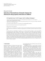
Figure 1: Motion directions defined in the cardiac cycle: (a) radial movement in terms of contraction and expansion; (b) horizontal rotation
is either clockwise or counterclockwise; and (c) vertical rotation is upwards or downwards. The two orientations for each direction are
colored by the defined coding scheme (see Section 2.1.1). Movements are depicted using the short axis view in (a) and (b) and the horizontal
long axis view in (c). The LV walls are depicted in (a) left: region 1 is the anterior wall; region 2 is the inferior wall; region 3 is the septal wall;
and region 4 is the lateral wall. (The nomenclatures of cardiac planes and wall segments used in this work follow the recommendations of
the American Heart Association, as described in Cerqueira et al. [18].)
z
r
θ
y
φ
r
z
y
xθ
φ
x
Figure 2: Unit vectors in spherical coordinates.
the velocity components for each voxel of the cardiac volume
in Cartesian coordinates. However, the spherical coordinate
system is a more suited system for the description of the
movements presented in the former item. For this reason,
the visualization module first performs a transformation of
the velocities obtained in x, y,andz directions to the unit
vectors in the directions r, θ, φ in the spherical coordinate
system (Figure 2).
The radial movement can be described by the unit vector
for the r component, the horizontal rotation by the unit
vector for the θ component, and the vertical movement by
the unit vector for the φ component.
The center of the spherical coordinate system is essential
when representing the left ventricular motion, as the origin
is the reference point for the motion. The results for the
velocity components are going to be highly dependent on
the choice of this point. How to choose the center of the
left ventricle is not a simple task. The anatomical center or
the center of mass might be used as a central point, but this
choice would fail to find the center in images from patients
with myocardial infarction or any disease in which the counts
are decreased at certain regions of the cardiac muscle. In this
work, the center is defined as the geometrical center of the LV
and is selected manually by a trained physician.
2.2.2. Color Scheme. A desired feature of the visualization
scheme is that all information concerning a movement direc-
tion be presented in a single image. Thus each image must
present information about the orientation and the intensity
of the velocity component. The color coding scheme is
therefore defined as following: for each component, the
color assigned to a voxel indicates the orientation of the
movement, being either positive or negative, and the strength
of the color indicates the intensity of the velocity vector in
this direction.
Positive and negative orientations for each movement
direction are defined as follows:
(i) Radial: expansion is positive; contraction is negative,
(ii) Horizontal rotation: clockwise rotation is negative,
and counterclockwise rotation is positive;
(iii) Vertical rotation: downwards motion is positive, and
upwards rotation is negative.
In order to indicate velocity intensity, a discrete lookup
table is used. In this table, the absence of motion is depicted
as white, positive values are depicted as blue, and negative
values are depicted as red. The positive and negative colors
are divided into 128 steps by changing their saturation, such
that strong movement is represented by a strong color, and
a weaker movement has a lighter color. Figure 3 shows an
example of a color scheme, in which the color variation
follows a linear scale. Logarithm scales can be used for better
visualization of weak movements.
2.3. Acquisition and Processing of Patient Images. The method
was applied to 3D gated-SPECT (99mTc-MIBI) images
obtained from sixteen patients with idiopathic dilated
cardiomyopathy, chronic heart failure in New York Heart
Association functional class III or IV, LV Ejection Fraction
<35%andleftbundlebranchblock(QRS
≥ 120 mil-
liseconds), referred for implantation of a CRT device. The
proposed protocol was approved by the Ethics Committee
4 EURASIP Journal on Advances in Signal Processing
Negative values
Positive values
Max negative Zero Max positive
Figure 3: Color scheme for presenting information on both the
intensity and orientation of the velocity: orientations with negative
values are red, and orientations with positive values are blue. The
faster a movement is, the stronger the color that represents it will
be.
of the University of Sao Paulo Medical School and an
informed consent was obtained from all study subjects
and/or their families. The image acquisitions were performed
at the Nuclear Medicine Department of the Heart Institute
(InCor) HCFMUSP. All acquisitions were performed after
the intravenous injection of 10 mCi of [technetium-99 m]
sestamibi at rest in a dual-head rotating gamma camera
(ADAC Cardio-MD with a LEAP Collimator). The acqui-
sition process is synchronized with the electrocardiogram
and the cardiac cycle was divided into 8 frames/cycle. A
total of 64 projections were obtained over a semicircular
180-deg orbit. All projection images were stored using a
64
× 64, 16-bit matrix. The transverse tomograms were
reconstructed with a thickness of 1pixel/slice (6.47 mm). The
volume of transverse tomograms was reoriented, and sets of
slices perpendicular to the long axis (short axis view) and
of slices parallel to the long axis (vertical long axis view and
horizontal long axis view) were created. For each patient the
images were acquired in two different conditions: at rest and
after pharmacological induced stress.
From the group of sixteen patients, eight were responders
to the CRT (Group1), and eight patients were nonresponders
(Group2). For each patient, the rest and stress data sets were
analyzed before to and after CRT, respectively. This gave a
total of 64 gated-SPECT data sets included in this analysis.
Before the implantation of the CRT device, the clinical condi-
tion of the patients was assessed and they were subsequently
scanned with three different image modalities: gated-SPECT,
echocardiography, and gated blood pool imaging. The aim
was to gain an estimated left ventricular Ejection Fraction
(EF) from each image modality, for later use as a quantitative
measure of the response. After a three-month follow-up, the
patients were submitted to the same procedures as prior to
CRT. The majority of patients improve immediately their EF
or functional class post-CRT implant. Estimates of the EF
from each image modality were acquired a second time and
compared with the estimated baseline EF. A positive response
to CRT was defined as an increase of at least 5 percent points
in one or more of the three modalities in addition to a
positive clinical assessment. Patients who showed a positive
response are named responders, and the ones who did not are
named nonresponders.
The method was also applied to image sets of thirty
normal subjects (The normal subjects whose images were
used in this work were part of a Research protocol approved
by the Ethics comittee of the University of Sao Paulo Medical
School.), whose acquisition protocol is the same as the one
described for the patient images.
3. Results: Application of the Method to
Investigate Some Aspects of CRT
3.1. Results for Normal Subjects. By analyzing normal left
ventricles, the resulting visualization of the motion patterns
can be compared with the motion expected from the heart
physiology (seen in Figure 1).
As an example, Figure 4 shows the results obtained for
one normal subject using the velocity color coding scheme.
The Figure depicts the velocity images for the three move-
ment directions in a slice from the midcavity portion at both
diastole (line 1) and systole (line 2). Column (a) presents
the images of the radial component, column (b) presents the
images of the horizontal rotation component, and column
(c) presents the images of the vertical component. The color
table used in Figure 4 (as in the remaining figures of this text)
is adjusted to the maximum value of each map.
3.1.1. Radial Movement. During systole, as the left ventricle
ejects blood, the myocardium contracts starting at the apex
and moving upwards to the base. Simultaneously, the septal
and lateral walls move towards the center of the left ventricle.
Therefore, the expected result in systole is the contraction
which is presented in the Figure 4, line 2, column a. In
this image, the contraction movement is represented by
different tones of red, indicating the contraction with varying
intensities. After ejection the heart enters the diastole,
where the overall motion is opposite of the contraction.
The expected colors are therefore also the opposite of the
ones observed in systole. The results of a normal wall
behavior can be observed in Figure 4, line 1, column a, where
the expansion movement is depicted as different tones of
blue.
3.1.2. Horizontal Rotation. The analysis of this movement is
quite complicated. If one studies the anatomy and physiology
of the subepicardial and subendocardial myofibres during
both systole and diastole, it would be expected that images
would show opposite rotations in the outer and inner sides
of the myocardium. This could not be seen in any of the
slices of any subjects. Instead, it seems like different rotary
motions govern at different parts of the myocardium. The
results in the midcavity slices form four corners, where
opposing corners have movements with the same direction
(see Figure 4, lines 1 and 2, column b). This pattern was
similar in all normal left ventricles, hence it was assumed
as the normal pattern in the horizontal motion. The results
obtained show the expected opposite relationship between
systole and diastole.
3.1.3. Vertical Rotation. In the ejection phase, the apex is
pressed upwards during contraction to force the blood out
through the aortic valve. The expected result of the vertical
rotation in systole is therefore an upwards rotation, which
is coded as red, this is also seen in Figure 4, line 2, column
c. In diastole, the images show movement in the opposite
direction.
EURASIP Journal on Advances in Signal Processing 5
(1)
(2)
(a) (b)
+0.8
0
−0.8
+0.8
0
−0.8
(c)
Figure 4: Velocity images of a normal subject in a slice from the midcavity portion of the LV. Line 1 presents diastolic images and line 2
presents systolic images. Column (a) depicts the images of the radial component. The several tones of blue in the myocardium in Line 1
represent the expansion while the tones of red in the same region in Line 2 represent the contraction. Column (b) presents the images of the
horizontal rotation component. The tones of blue represent counterclockwise rotation while the tones of red represent clockwise rotation.
Column (c) presents the images of the vertical component. The tones of blue represent downward motion while the tones of red represent
upward motion. The color scale is shown at the top right of the figure.
3.2. Results for Patients
3.2.1. Radial Movement. In both groups of patients, the
dyssynchrony of the movement can be observed in the radial
movement. After CRT, Group1 should achieve an improved
synchronization in the radial motion. This can be seen
in most of the analyzed patients, where improvement in
synchrony between septal and lateral wall is detected in both
systole and diastole. Figure 5 shows an example of such a
patient.
Prior to CRT a dyssynchrony is present in form of a blue
(expanding) septal wall and a red (contracting) lateral wall.
In the image after CRT, an improved synchrony is visible;
here the blue color in the circle is replaced by a weak red
color. During diastole in Figure 5, only the lateral wall is
expanding before CRT, as the septal wall was expanding in
systole. After CRT a more synchronic expansion is detected.
It is seen that the overall intensity of the movement is
weaker when compared to the normal subjects. The analysis
of synchrony in the Group2 showed that there was no
improvement in most of patients, as expected.
3.2.2. Horizontal Rotation. TheimagesobtainedbeforeCRT
present patterns quite different from the one assumed as the
normal pattern. However, most of the results for Group1
after CRT are like the pattern found for the normal left
ventricles; an example is shown in Figure 6. The example in
Figure 6 further shows that the desired opposite relationship
between systole and diastole is present.
For Group2 no such pattern in the horizontal rotation
was detected. One patient showed a pattern similar to a
normal pattern in systole, but a worsening in diastole, while
others showed the opposite or a mixture of rotations. None
of the patients had a similar pattern of improvement or
deterioration in synchrony. The intensity of motion was
similar prior to and after CRT in all patients in systole,
but in diastole half of the patients had a high intensity
in horizontal rotation before CRT, which decreased after
CRT. This behavior of noticeable decreased velocity intensity
values was not detected in the Group1.
3.2.3. Vertical Rotation. A dyssynchrony in the vertical
rotation is present in varying degrees in the results, which is
expected for heart failure patients. Most of Group1 patients
showed an improvement after CRT. For Group2, however,
the normal pattern was hardly obtained even after CRT. In
the case of horizontal rotation mentioned in the former
section, some Group2 patients had a high intensity in
diastole. The same patients had a high intensity in the vertical
rotation in diastole. As it was seen in the horizontal rotation,
the intensity of the vertical rotation also decreased after CRT.
Figure 7 presents the results for a Group1 patient
6 EURASIP Journal on Advances in Signal Processing
Before CRT After CRT
Contraction of
the lateral wall
Systole
Expansion of
the septal wall
Diastole
Contraction of
lateral and
septal walls
+0.25
0
−0.25
+0.25
0
−0.25
Figure 5: Radial motion of a Group1 patient. A slice from the midcavity is shown in systole and diastole, before and after CRT. In systole
before CRT, the arrows indicate the septal and lateral walls. It can be noticed that in the septal wall, pixels present positive values—blue
color—while in the lateral wall they present negative values—red color. The expected normal movement would be an overall contraction of
the walls, represented by red color. Such movement can be seen in systole after CRT. The arrows in the figure indicate the global contraction
movement depicted in tones of reds. The color scale is shown at the top right of the figure.
Before CRT After CRT
Systole
Diastole
+0.3
0
−0.3
+0.3
0
−0.3
Figure 6: Horizontal motion of a Group1 patient. A slice from the midcavity is shown in systole and diastole, and before and after CRT. A
movement pattern similar to the normal is seen after CRT in both systole and diastole. The color scale is shown at the top right of the figure.
EURASIP Journal on Advances in Signal Processing 7
Before CRT After CRT
Systole
Diastole
+0.32
0
−0.32
+0.32
0
−0.32
Figure 7: Vertical rotation in a Group1 patient. Middle slices shown during systole and diastole before and after CRT. The pattern is similar
to the normal pattern before and after CRT as well as in systole and diastole. The color scale is shown at the top right of the figure.
3.3. Analysis of Radial Movement—Normal and Patient.
Ta bl e 1 presents the normalized mean velocity values for the
radial motion of the anterior, inferior, septal, and lateral walls
(Figure 1(a)) for the LV midcavity portion. It presents the
values found for one normal subject and one patient of each
group (responder and nonresponder).
The comparison between patients (Group1 and Group2)
and normal subjects shows that not only the synchrony
of the movement is compromised, but the intensity is
seriously decreased in this set of patients, which reflects the
impaired heart function. The numerical values representing
the quantity of movement of the normal subjects are ten
times higher than the patients. Although this quantity
does not change considerably before and after the CRT,
the responder patient presents an overall increase in the
clinical conditions due to the fact that the synchrony of the
movement has been restored. This fact can be seen in Tab le 1
by the change in the expected sign for the measurement.
Patients from the Group2 did not present this improvement
in synchrony.
4. Discussion and Conclusions
The analysis of the velocity field from cardiac volumes can
give important clues about the dynamic events occurring
during the cardiac cycle, which may help to understand how
some treatments improve heart function. In this work, the
results were presented in a slice of the short axis view and we
proposed a scheme for displaying the wall movements which
are displayed using a compressive color code that integrates
orientation and intensity of the velocity vector at each voxel.
The most important feature of this method is its capabil-
ity to evaluate LV motion in a more comprehensive way since
it allows a regional analysis by assessing the movement in
three predefined directions. Other techniques (like echocar-
diography and phase images derived from Fourier transform
of radionuclide ventriculography or even gated single photon
emission computed tomography) use previously defined
points (or regions) and establish a comparison between them
or evaluate indices that characterize global LV synchrony
[2, 7, 10, 19].
In this study, the results from the normal subjects were
used as the reference for normality in each of the directions.
The representation of the velocity components in a color
coded image has shown to be an efficient tool for regional
inspection of the LV wall movement that could improve the
optimal site of LV electrode implant. Actually, the method
allows a local analysis, since the results are obtained for each
voxel of the volume. This is an important advantage of this
method when compared to other global techniques such as
phase and amplitude.
Ta bl e 1 shows a quantitative comparison of one data set
obtained in normal controls, and two patients, one who
responded to CRT and one nonresponder. A difference of
one order of magnitude in the intensity of the movement on
patients in relation to the normal subjects was observed. The
evaluation of radial motion before CRT in a nonresponder
patient (group 2) showed a movement pattern different from
normal in both phases of the cardiac cycle. The responder
(group 1) showed motion in the opposite direction from nor-
mal controls only in inferior and septal walls. This fact could
suggest that responders are different from nonresponders
8 EURASIP Journal on Advances in Signal Processing
Table 1: Mean intensity values for radial motion of one normal subject and two patients, one of Group1 and one of Group2, before and after
CRT. Values presented for the walls depicted in Figure 1—anterior, inferior, septal, and lateral—for the LV midcavity portion. The computed
intensity values are mapped to a scale that allows a maximum of +1 and a correspondent minimum of
−1.
Anterior wall Inferior wall Septal wall Lateral wall
Diast Syst Diast Syst Diast Syst Diast Syst
Expected orientation + − + − + − + −
Normal +0.738 −0.344 +0.474 −0.278 +0.404 −0.144 +0.808 −0.600
Group1
before +0.006
−0.056 −0.038 +0.016 −0.008 +0.056 +0.066 −0.062
After +0.026
−0.044 +0.020 +0.028 +0.028 −0.044 +0.100 −0.062
Group2
Before 0.000 +0.016
−0.026 +0.068 −0.030 +0.040 +0.046 +0.062
After
−0.028 +0.068 +0.128 −0.004 −0.006 −0.004 +0.104 −0.002
Diast: values in diastole; Syst: values in systole; Expected orientation of the movement: + is expansion and – is contraction; Group1 before: responder patient
before CRT; Group1 after: responder patient after CRT; Group2 before: patient nonresponder before CRT; Group2 after: patient nonresponder after CRT.
before therapy. After therapy, the direction of the motion of
inferior and lateral walls of the nonresponder became similar
to normal controls, but not the direction of anterior and
septal walls. The group 1 patient showed a normal motion
pattern except in inferior wall after therapy. The qualitative
and quantitative parameters obtained with this method
could add information to a better selection of patients who
would respond to TRC and provide a measurable tool to the
follow-up in this population.
Limitations. the spherical coordinate system was chosen
for calculating the orientation and intensity of the left
ventricular motion. A key issue to the proposed scheme is
the center of the spherical coordinate system since it is the
reference point for the motions and therefore essential in
the visualization of the velocity components. A change in
center will influence both the intensity and orientation of
the left ventricular motion. Choosing the center is difficult
as it should be the exact point or axis from which the
motion starts and ends. In the present work, the center
was determined manually by a trained observer as the
geometrical center of the LV.
Another limitation is the poor resolution of SPECT
images that sometimes makes it difficult to analyze the
movements. It must be added, however, that the proposed
method is not applicable to nuclear medicine imaging only
and can be extended to other modalities.
Future Perspectives and Conclusions. the results are pre-
liminary indications obtained via a qualitative assessment.
Quantitative indexes can be created based on these images
that would be able to quantitatively assess both the effective-
ness and prediction of CRT response. These indexes could
be based on the creation of normal distributions of the
velocity field for each direction. An alternative and elegant
approach for defining quantitative tools for the analysis of
the movement patterns is the creation of a functional bull’s
eye [20–23]. Once the bull’s eyes of the described movement
patterns have been built, many studies can be performed for
the assessment of the patient’s condition. In order to find an
index to predict response to CRT therapy, extensive clinical
studies must be performed and involve the acquisition of
a statistically significant number of images from normal
subjects and patients.
In this study, the left ventricular three-wall movements
were studied using a compressive color code that char-
acterizes the integration of orientation and intensity of
the velocity vector at each voxel. This new technique of
myocardial synchronization assessment might be able to
distinguish responder patients from the nonresponders and
improve the follow up of patients who underwent CRT.
Acknowledgments
The authors would like to thank Dr. Ramon Moreno,
Maur
´
ıcio Higa, and Carlos Santos for their valuable dis-
cussions at the elaboration of this work. This work was
supported in part by the Foundation of Aid for Research
of S
˜
ao Paulo State (FAPESP) Grant no. 2006/06612-4, the
National Council for Scientific and Technological Devel-
opment (CNPq) Grant no. 300499/2005-1, the National
Institute of Science and Technology—Medicine Assisted
by Scientific Computing INCT MACC, and the Zerbini
Foundation.
References
[1] E.W.Remme,A.A.Young,K.F.Augenstein,B.Cowan,and
P. J. Hunter, “Extraction and quantification of left ventricular
deformation modes,” IEEE Transactions on Biomedical Engi-
neering, vol. 51, no. 11, pp. 1923–1931, 2004.
[2] J. Chen, E. V. Garcia, R. D. Folks, et al., “Onset of left
ventricular mechanical contraction as determined by phase
analysis of ECG-gated myocardial perfusion SPECT imaging:
development of a diagnostic tool for assessment of cardiac
mechanical dyssynchrony,” Journal of Nuclear Cardiology, vol.
12, no. 6, pp. 687–695, 2005.
[3] K. Rioual, E. Unanua, S. Laguitton, et al., “MSCT labelling for
pre-operative planning in cardiac resynchronization therapy,”
Computerized Medical Imaging and Graphics,vol.29,no.6,pp.
431–439, 2005.
[4] A. Auricchio and W. T. Abraham, “Cardiac resynchronization
therapy: current state of the art: cost versus benefit,” Circula-
tion, vol. 109, no. 3, pp. 300–307, 2004.
[5] C. Linde, F. Braunschweig, F. Gadler, C. Bailleul, and J
C. Daubert, “Long-term improvements in quality of life by
EURASIP Journal on Advances in Signal Processing 9
biventricular pacing in patients with chronic heart failure:
results from the MUltisite STimulation In Cardiomyopathy
Study (MUSTIC),” American Journal of Cardiology, vol. 91, no.
9, pp. 1090–1095, 2003.
[6] G. Lecoq, C. Leclercq, E. Leray, et al., “Clinical and elec-
trocardiographic predictors of a positive response to cardiac
resynchronization therapy in advanced heart failure,” Euro-
pean Heart Journal, vol. 26, no. 11, pp. 1094–1100, 2005.
[7] G. B. Bleeker, J. J. Bax, J. W H. Fung, et al., “Clinical versus
echocardiographic parameters to assess response to cardiac
resynchronization therapy,” American Journal of Cardiology,
vol. 97, no. 2, pp. 260–263, 2006.
[8] C M. Yu, G. B. Bleeker, J. W H. Fung, et al., “Left ventricular
reverse remodeling but not clinical improvement predicts
long-term survival after cardiac resynchronization therapy,”
Circulation, vol. 112, no. 11, pp. 1580–1586, 2005.
[9] S. Yeim, P. Bordachar, S. Reuter, et al., “Predictors of a positive
response to biventricular pacing in patients with severe heart
failure and ventricular conduction delay,” Pacing and Clinical
Electrophysiology, vol. 30, no. 8, pp. 970–975, 2007.
[10] S. C. S. Brand
˜
ao,M.C.P.Giorgi,R.T.deMiche,etal.,
“Ventricular synchrony in patients with dilated cardiomy-
opathy and normal individuals: assessment by radionuclide
ventriculography,” Arquivos Brasileiros de Cardiologia, vol. 88,
no. 5, pp. 596–601, 2007.
[11] S. A. Strickberger, J. Conti, E. G. Daoud, et al., “Patient selec-
tion for cardiac resynchronization therapy: from the Council
on Clinical Cardiology Subcommittee on Electrocardiography
and Arrhythmias and the Quality of Care and Outcomes
Research Interdisciplinary Working Group, in collaboration
with the Heart Rhythm Society,” Circulation, vol. 111, no. 16,
pp. 2146–2150, 2005.
[12] J. W. O’Connell, C. Schreck, M. Moles, et al., “A unique
method by which to quantitate synchrony with equilibrium
radionuclide angiography,” Journal of Nuclear Cardiology, vol.
12, no. 4, pp. 441–450, 2005.
[13] J. Declerck, J. Feldmar, and N. Ayache, “Definition of a four-
dimensional continuous planispheric transformation for the
tracking and the analysis of left-ventricle motion,” Medical
Image Analysis, vol. 2, no. 2, pp. 197–213, 1998.
[14] S. R. R. Tecel
˜
ao, J. J. M. Zwanenburg, J. P. A. Kuijer, et al.,
“Quantitative comparison of 2D and 3D circumferential strain
using MRI tagging in normal and LBBB hearts,” Magnetic
Resonance in Medicine, vol. 57, no. 3, pp. 485–493, 2007.
[15] G. J. Klein, B. W. Reutter, and R. H. Huesman, “Non-rigid
summing of gated PET via optical flow,” IEEE Transactions on
Nuclear Science, vol. 44, no. 4, pp. 1509–1512, 1997.
[16]M.A.Gutierrez,M.S.Rebelo,S.S.Furuie,andJ.C.
Meneghetti, “Automatic quantification of three-dimensional
kinetic energy in gated myocardial perfusion single-photon-
emission computerized tomography improved by a multires-
olution technique,” Journal of Electronic Imaging, vol. 12, no.
1, pp. 118–124, 2003.
[17] B. K. P. Horn and B. G. Schunck, “Determining optical flow,”
Artificial Intelligence, vol. 17, no. 1–3, pp. 185–203, 1981.
[18] M. D. Cerqueira, N. J. Weissman, V. Dilsizian, et al.,
“Standardized myocardial segmentation and nomenclature
for tomographic imaging of the heart: a statement for
healthcare professionals from the Cardiac Imaging Committee
of the Council on Clinical Cardiology of the American Heart
Association,” Circulation, vol. 105, no. 4, pp. 539–542, 2002.
[19] S. C. S. Brand
˜
ao,S.A.D.Nishioka,M.C.P.Giorgi,etal.,
“Cardiac resynchronization therapy evaluated by myocardial
scintigraphy with
99m
TC-MIBI: changes in left ventricular
uptake, dyssynchrony, and function,” European Journal of
Nuclear Medicine and Molecular Imaging,vol.36,no.6,pp.
986–996, 2009.
[20] R. J. Qureshi and S. A. Husain, “Design of na expert system
for diagnosis of coronary artery disease using myocardial
perfusion imaging,” in Proceedings of the National Conference
on Emerging Technologies, pp. 100–105, 2004.
[21] N. Rougon, C. Petitjean, F. Pr
ˆ
eteux, P. Cluzel, and P. Grenier,
“A non-rigid registration approach for quantifying myocardial
contraction in tagged MRI using generalized information
measures,” Medical Image Analysis, vol. 9, no. 4, pp. 353–375,
2005.
[22] O. G
´
erard, A. C. Billon, J M. Rouet, M. Jacob, M. Fradkin,
and C. Allouche, “Efficient model-based quantification of
left ventricular function in 3-D echocardiography,” IEEE
Transactions on Medical Imaging, vol. 21, no. 9, pp. 1059–1068,
2002.
[23] J W. Lin, A. F. Laine, and S. R. Bergmann, “Improving
PET-based physiological quantification through methods of
wavelet denoising,” IEEE Transactions on Biomedical Engineer-
ing, vol. 48, no. 2, pp. 202–212, 2001.