Recent Advances in Biomedical Engineering 2011 Part 10 pdf
Bạn đang xem bản rút gọn của tài liệu. Xem và tải ngay bản đầy đủ của tài liệu tại đây (6.38 MB, 40 trang )
Wideband Technology for Medical Detection and Monitoring 349
3.2 Implementation and Testing
The feasibilty of UWB signal tranmission within a human body is shown in this section. A
band limited UWB prototytpe system described earlier has been tested in a laboratory
environtment for wireless endocsope monitoring systems. In this section the
implementation details and measurement results interms of time signals and frequency
spectrums at different stages of the UWB prototype system are presented, with capsule-
shaped antennas at both the transmitter and receiver end. Main challenges associated with
the design of microelectronics for implantable electronics are miniaturization, antenna
design and saving the battery life. The microsystems will contain four main blocks,
battery/power management circuitry, camera/sensors, transmitter (UWB transmitter) and
antenna design. Integration of antenna with UWB transmitter electronics should be
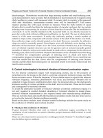
considered in a capsule shaped structure, ideally size000. Since miniaturization is important,
different design approaches can be followed. As an example, each block on a separate board
layer and then integrate them on top of each other as shown in Fig. 10 is a good approach to
follow for a better miniaturization. In a different design shown in Fig. 10-(a) antenna can be
designed such that it can easily be inserted on top of the transmitter layer. In Fig. 10-(b), the
capsule shape is divided into two regions where antenna will be designed to be placed in
upper-half whereas the remaining electronic units could be placed in the lower-half. Placing
electronic units on one side of antenna is another possibility, Fig. 10-(c). There are
commercially available mini cameras that can easily be integrated in electronic pill
technology (STMicroelectronics. Online. (2009)). Small miniature rechargeable battery
technologies are also being developed (smallbattery, 2009; buybionicear (http://
www.buybionicear.ca/), 2009). These batteries have a dimension around 5 mm and can
easily be integrated in a capsule shape structure shown in Fig 10.
Fig. 10. Possible physical shapes for future implantable electronic pills.
The antennas that have been previously reported for endoscope applications operate in a
lower frequency band (Kwak et al., 2005) A low-cost, printed, capsule-shaped UWB antenna
has been designed for the targeted application (Dissanayake et al., 2009). The printed
antenna presented herein demonstrates good matching in the frequency band of 3.5-4.5GHz
and the radiation performance has been evaluated experimentally using a low-power I-
UWB transmitter/receiver prototype to show that it is suitable for the implantable wireless
endoscope monitoring. The antenna matching has been optimized using CST microwave
studio commercial electromagnetic simulation software. Proposed antenna is printed on a
0.5mm thick RO4003 capsule-shaped, low loss, dielectric substrate (
38.3
r
). It can
easily fit inside a size-13 capsule (Capsule, 2000) , ingestible by large mammals. Overall
length and width of the antenna is 28.7mm and 14mm, respectively. It is primarily a planar
dipole, which has been optimized using simulations and printed on one side of the substrate
together with a Grounded-CPW (Coplanar Wave Guide) feed as shown in Fig. 11.
2.64
1.14
R 1.00
R 1.75
4.00
2.64
5.00
R 7.00
5.00
1.29
4.70
8.00
Y
X
0.50
1.65
50 Ohm Probe
Connector
Flange
Battery/Power
Management
CAMERA/
SENSORS
UWB
Transmitter
Fig. 11. A wireless endoscope monitoring system with antenna dimensions.
Grounded-CPW has characteristic impedance of 50 Ohms and the ground plane on the
opposite side of the substrate is intended to support other electronics as shown in Fig. 11.
This avoids performance degradation upon integration with other electronics, batteries and
connectors. A panel mount SMA connector is used in place of these electronics for testing.
Flange of the connector acts as a ground plane to the CPW. The circular pad in one end of
the grounded-CPW facilitates broadband coaxial-to-CPW transition (Kamei et al., 2007).
The feed line has an effective dielectric constant of 2.62 at 3.5 GHz (lower end of the
matched band). Therefore, the guided wavelength at that frequency is approximately 53mm,
which is less than that of a CPW. The overall antenna length, 28.7mm, is close to half the
guided wavelength, which is typical for a dipole. Hence the additional ground plane, which
also is a part of the feed line, has contributed to the miniaturization of the antenna. As a
result, largest dimension of the proposed antenna is only 0.3 times the free space
wavelength at 3.5 GHz, 40% less compared to half of free space wavelength. On top of this
dielectric loading of the antenna may be employed to achieve further antenna
miniaturization. Three symmetrically placed vias ensure electrical connection between the
patch on one side of the substrate and the flange of the connector on the other side. The
Recent Advances in Biomedical Engineering350
radius of each via is 0.75mm. Parametric studies have shown that the distance to the vias
from the center of the coaxial feed affects the input impedance of the antenna. Note that the
patch, flange and each via form shorted transmission line resonators. At certain lengths, the
resonant frequency of the standing waves created by via reflections can be between 3.5 and
4.5 GHz, resulting an in-band notch, which is not desirable. Thus we have selected 4mm as
the optimum distance.
Two antenna prototypes have been fabricated using conventional printed circuit board
design techniques. This makes the antenna low cost. Reflection coefficients of both antennas
have been measured using E5071B vector network analyzer from Agilent. Measured results
and simulated S11 values from CST Microwave Studio are shown in Fig. 12. There is a good
agreement between measured and theoretical S11 results. Antennas have greater than 10dB
return loss from 3.4-4.6 GHz. Simulations suggests that the proposed antenna has radiation
patterns (not shown) similar to that of a dipole antenna. Theoretical gain at 4 GHz is 2.23dBi.
It allows about -45dBm/Hz output power of the UWB transmitter under the regulations in
free space. Higher transmitter power or antenna gain is possible for in-body transmission as
we shall discuss shortly.
Fig. 12. Theoretical and measured reflection coefficients of the UWB antenna.
3.3 Experiments for Tissue Penetration
Our objective is to demonstrate the designed antenna and UWB prototype is capable of
supporting a low-power UWB communication, which will be ultimately used to form an in-
body-to-air link, without FCC violating regulations. The setup used in the experiment is
shown in Fig. 13. The diameter of the plastic container is 75mm. The network analyzer
(VNA) used is calibrated for full range. Salt reduced Corned Beef Silverside has been used
as meat. One antenna is fixed at the bottom of the container, while the other is flushed into
meat during the measurement. Both antennas were coated with clear rubber coating from
Chemsearch
TM
, to prevent any contact with meat or fluids.
Fig. 13. Experimental setup of a UWB transmitter with capsule shaped antenna loaded with
tissue material.
The coating did not have any effect on the antennas’ characteristics. Antennas were held
parallel so that coupling through meat is in bore sight. Prior to each measurement, jacket of
aluminum foil covered the outer surface of the container to minimize outside coupling paths
between the antennas. Measured S21 using the VNA is shown in Fig. 14. Coupling between
antennas in the same laboratory environment and instrument calibration, for both through
the meat and free space, are shown for comparison. There is about 20-30 dB attenuation
through meat within 3-5GHz band for every 2 cm. This attenuation is not entirely due to
absorption by meat. The antenna mismatch due to presence of meat also contributes to this.
-100.00
-90.00
-80.00
-70.00
-60.00
-50.00
-40.00
-30.00
-20.00
-10.00
0.00
0.00 1.00 2.00 3.00 4.00 5.00 6.00 7.00 8.00 9.00
Frequency (GHz)
S12 (dB)
Through 2cm Meat
Through 2cm Free Space
Fig. 14. Antenna coupling through meat (s21 measurement).
For a UWB transmitter, the regulation requires the signal output to be -41 dBm/Hz and
lower with 0dBi antenna gain (Arslan et al., 2006). To make the UWB transmission feasible
for implantable devices, higher transmitted signal levels can be used at the implanted
transmitter side. The UWB signal power is arranged such that when the signal is radiated
through the skin, the power level should meet the FCC mask. Fig. 15 shows acceptable
transmitted power levels of the implanted transmitter for different penetration depths,
Wideband Technology for Medical Detection and Monitoring 351
radius of each via is 0.75mm. Parametric studies have shown that the distance to the vias
from the center of the coaxial feed affects the input impedance of the antenna. Note that the
patch, flange and each via form shorted transmission line resonators. At certain lengths, the
resonant frequency of the standing waves created by via reflections can be between 3.5 and
4.5 GHz, resulting an in-band notch, which is not desirable. Thus we have selected 4mm as
the optimum distance.
Two antenna prototypes have been fabricated using conventional printed circuit board
design techniques. This makes the antenna low cost. Reflection coefficients of both antennas
have been measured using E5071B vector network analyzer from Agilent. Measured results
and simulated S11 values from CST Microwave Studio are shown in Fig. 12. There is a good
agreement between measured and theoretical S11 results. Antennas have greater than 10dB
return loss from 3.4-4.6 GHz. Simulations suggests that the proposed antenna has radiation
patterns (not shown) similar to that of a dipole antenna. Theoretical gain at 4 GHz is 2.23dBi.
It allows about -45dBm/Hz output power of the UWB transmitter under the regulations in
free space. Higher transmitter power or antenna gain is possible for in-body transmission as
we shall discuss shortly.
Fig. 12. Theoretical and measured reflection coefficients of the UWB antenna.
3.3 Experiments for Tissue Penetration
Our objective is to demonstrate the designed antenna and UWB prototype is capable of
supporting a low-power UWB communication, which will be ultimately used to form an in-
body-to-air link, without FCC violating regulations. The setup used in the experiment is
shown in Fig. 13. The diameter of the plastic container is 75mm. The network analyzer
(VNA) used is calibrated for full range. Salt reduced Corned Beef Silverside has been used
as meat. One antenna is fixed at the bottom of the container, while the other is flushed into
meat during the measurement. Both antennas were coated with clear rubber coating from
Chemsearch
TM
, to prevent any contact with meat or fluids.
Fig. 13. Experimental setup of a UWB transmitter with capsule shaped antenna loaded with
tissue material.
The coating did not have any effect on the antennas’ characteristics. Antennas were held
parallel so that coupling through meat is in bore sight. Prior to each measurement, jacket of
aluminum foil covered the outer surface of the container to minimize outside coupling paths
between the antennas. Measured S21 using the VNA is shown in Fig. 14. Coupling between
antennas in the same laboratory environment and instrument calibration, for both through
the meat and free space, are shown for comparison. There is about 20-30 dB attenuation
through meat within 3-5GHz band for every 2 cm. This attenuation is not entirely due to
absorption by meat. The antenna mismatch due to presence of meat also contributes to this.
-100.00
-90.00
-80.00
-70.00
-60.00
-50.00
-40.00
-30.00
-20.00
-10.00
0.00
0.00 1.00 2.00 3.00 4.00 5.00 6.00 7.00 8.00 9.00
Frequency (GHz)
S12 (dB)
Through 2cm Meat
Through 2cm Free Space
Fig. 14. Antenna coupling through meat (s21 measurement).
For a UWB transmitter, the regulation requires the signal output to be -41 dBm/Hz and
lower with 0dBi antenna gain (Arslan et al., 2006). To make the UWB transmission feasible
for implantable devices, higher transmitted signal levels can be used at the implanted
transmitter side. The UWB signal power is arranged such that when the signal is radiated
through the skin, the power level should meet the FCC mask. Fig. 15 shows acceptable
transmitted power levels of the implanted transmitter for different penetration depths,
Recent Advances in Biomedical Engineering352
approximately based on the results of our experiment. At 2cm, we can allow for as much as
20 dBm of transmitted power, which would ultimately meet regulated spectral density
requirements after penetration through tissue. Thus considering the strong attenuation
through body tissue, the transmitter power level can be adjusted from -20 dBm to 20 dBm in
the system, without violating power levels of FCC regulation. Of course, the power levels
should not reach above regulated in-body tissue absorption levels. A special case of
electronic pills is that the device travels in the body, it does not stay in the same area (unlike
the stationed implants), and thus increasing power levels will not increase the heat much at
the tissue of a certain body part.
Fig. 15. Power levels of transmitted UWB signal in body.
3.4 Testing and Measurements
In the I-UWB setup, pulses have been generated based on an all digital approach described
in section 2.2. Fig. 16 shows the UWB prototype with transmitter and receiver with
waveforms shown explicitly. Short pulses are generated according to the on-off keying
(OOK) modulated signal. At the transmitter, the pulse generator unit produces a
rectangular-shaped pulse with 1ns width, as shown in Fig 16 (a). The spectrum of the
rectangular pulse extends over an unlimited frequency band. Thus a Band Pass Filter (BPF)
centered at 4 GHz with 1 GHz bandwidth is used to constrain the signal power under the
FCC emission mask (i.e. a band limited UWB system). The energy of the side lobes is
maximized within the bandwidth of the bandpass filter as discussed in Section 2.2. The
filtered pulses are fed into our custom made UWB antenna. The UWB signal has shown
good performance in the frequency band of 3.5- 4.5 GHz. It has also shown its ability to form
a 0.6 m UWB link across the laboratory both in free-space and when loaded with meat
emulating an implant once a high gain antenna is used at the receiver instead of one shown
in Fig. 16-(b).
Fig. 16. A ultra wideband (UWB) wireless telemetry prototype and measurement results,(a)
transmitter with 1 ns UWB pulse, and (b) receiver with spectrums at the output of antenna
and after RF amplifications.
Despite the simplicity of the transmitter design, several limitations arise when designing a
practical UWB receiver. A major challenge faced by an UWB receiver is its capability to
demodulate the narrow pulses. A coherent receiver requires a very high speed ADC
(Analog-to-Digital Converter) with a large analog input bandwidth. Secondly, it is hard to
achieve precise synchronization, which is critical for the reliable operation of coherent
receiver. In this experiment, a non-coherent energy detector method is used to demodulate
the received signal.
There are different receiver architectures that can easily be constructed using high
performance off-shelf RF components. Usually a mixer is used to down convert the high
frequencies to low frequencies (Ryckaert et al., 2007). Herein a diode is used due to
simplification in the successive blocks (See Fig. 16 (b)). The received signal is passed through
a BPF, whose center frequency is 4 GHz, to eliminate possible interference from the
Wideband Technology for Medical Detection and Monitoring 353
approximately based on the results of our experiment. At 2cm, we can allow for as much as
20 dBm of transmitted power, which would ultimately meet regulated spectral density
requirements after penetration through tissue. Thus considering the strong attenuation
through body tissue, the transmitter power level can be adjusted from -20 dBm to 20 dBm in
the system, without violating power levels of FCC regulation. Of course, the power levels
should not reach above regulated in-body tissue absorption levels. A special case of
electronic pills is that the device travels in the body, it does not stay in the same area (unlike
the stationed implants), and thus increasing power levels will not increase the heat much at
the tissue of a certain body part.
Fig. 15. Power levels of transmitted UWB signal in body.
3.4 Testing and Measurements
In the I-UWB setup, pulses have been generated based on an all digital approach described
in section 2.2. Fig. 16 shows the UWB prototype with transmitter and receiver with
waveforms shown explicitly. Short pulses are generated according to the on-off keying
(OOK) modulated signal. At the transmitter, the pulse generator unit produces a
rectangular-shaped pulse with 1ns width, as shown in Fig 16 (a). The spectrum of the
rectangular pulse extends over an unlimited frequency band. Thus a Band Pass Filter (BPF)
centered at 4 GHz with 1 GHz bandwidth is used to constrain the signal power under the
FCC emission mask (i.e. a band limited UWB system). The energy of the side lobes is
maximized within the bandwidth of the bandpass filter as discussed in Section 2.2. The
filtered pulses are fed into our custom made UWB antenna. The UWB signal has shown
good performance in the frequency band of 3.5- 4.5 GHz. It has also shown its ability to form
a 0.6 m UWB link across the laboratory both in free-space and when loaded with meat
emulating an implant once a high gain antenna is used at the receiver instead of one shown
in Fig. 16-(b).
Fig. 16. A ultra wideband (UWB) wireless telemetry prototype and measurement results,(a)
transmitter with 1 ns UWB pulse, and (b) receiver with spectrums at the output of antenna
and after RF amplifications.
Despite the simplicity of the transmitter design, several limitations arise when designing a
practical UWB receiver. A major challenge faced by an UWB receiver is its capability to
demodulate the narrow pulses. A coherent receiver requires a very high speed ADC
(Analog-to-Digital Converter) with a large analog input bandwidth. Secondly, it is hard to
achieve precise synchronization, which is critical for the reliable operation of coherent
receiver. In this experiment, a non-coherent energy detector method is used to demodulate
the received signal.
There are different receiver architectures that can easily be constructed using high
performance off-shelf RF components. Usually a mixer is used to down convert the high
frequencies to low frequencies (Ryckaert et al., 2007). Herein a diode is used due to
simplification in the successive blocks (See Fig. 16 (b)). The received signal is passed through
a BPF, whose center frequency is 4 GHz, to eliminate possible interference from the
Recent Advances in Biomedical Engineering354
frequencies of Wireless Local Area Network (WLAN) standards (for example 2.4 GHz and 5
GHz). The signal is then amplified by the Low Noise Amplifier (LNA). A diode and a Low
Pass Filter (LPF) down converts the UWB signal and the baseband data is finally recovered
by the FGPA.
At the receiver end, the main component is the diode detector. When small input signals
below -20dBm are applied to the diode, it translates the high frequency components to their
equivalent low frequency counterparts due to its nonlinear characteristics. Measurement
results, shown in Fig. 16(b) are spectrum plots at the outputs of the receive antenna and the
low-noise amplifiers. The transmitted narrow UWB pulses are recovered at the output of the
diode. The 50 MHz data stream is obtained at the FPGA after the demodulation process. The
time domain signals before and after the FPGA are shown in Fig. 17. The recovered signal is
a 50 Mbps pulse obtained from pulses with width of 1ns.
Fig. 17. Received and demodulated UWB signals.
4. Wearable Medical Monitoring System
Deployment of wireless technology for wearable medical monitoring has improved patient‘s
quality of life and efficiency of medical staff. Several wireless technologies based on
Bluetooth, ZigBee, and WLAN are available for sensor network applications (given in Table
1); however they are not optimized for medical sensor networks and lack interoperability.
Therefore, there is a need for standardization to provide an optimized solution for medical
monitoring systems. A group (IEEE802.15.6) was formed in November 2007 to undertake
this task (WBAN standard, online, 2009). Low data rate UWB is one of the potential
candidates under consideration, to overcome the bandwidth limitations of current
narrowband system, and to improve the power consumption and size. In this part of the
chapter, a multi-channel wearable physiological signals monitoring system using ultra
wideband technology will be described.
4.1 Continuous Sign Monitoring Using UWB
An ultra wideband based low data rate recording system for monitoring multiple
continuous electrocardiogram (ECG) and electroencephalogram (EEG) signals have been
designed, and tested to show the feasibility of low data rate UWB in a medical monitoring
systems. There has been a wide spread use of wireless monitoring systems both in hospital
and home environments. Ambulatory ECG monitoring, EEG monitoring in emergency
departments, respiratory rate, SPO2 and blood pressure are now performed wirelessly
(WBAN standard, 2009; Ho & Yuce, 2007). The various wireless technologies adopted for
medical application are shown in Table 1. Low data rate UWB is suitable for vital signs
monitoring system as its transmission power is lower than those of WLAN, Bluetooth and
Zigbee (See Table 1), and is less likely to affect human tissue and cause interference to other
medical equipments. Furthermore, it is able to transmit higher data rates, which makes it
suitable for real time continuous monitoring of multiple channels. Currently, the task group
for Wireless Body Area Network (IEEE802.15.6) is considering the low data rate UWB
transmission as one of the wireless technologies for the wireless devices operating in or
around human body. Herein, a multiple channel monitoring system is designed and tested
to show the suitability of low data rate UWB transmission for non-invasive medical
monitoring applications. An 8-channel UWB recording system developed to monitor
multiple ECG and EEG signals is presented in Fig. 18. Commercial off-the-shelf digital gates
have been used for designing this UWB prototype system.
The system is designed to operate with a center frequency of 4 GHz and a pulse width of 1
ns, which is equivalent to 1 GHz bandwidth. An UWB transmitter is assembled using
commercial off-the-shelf components for transmission of physiological signals from an on-
body sensor node (Fig. 19). The UWB pulses are generated in a way to occupy the spectrum
efficiently and thus to optimize the wireless transmission The transmitter as shown in Fig.
19 generates and transmits multiple pulses per bit. A clock in the transmitter is used for this
Fig. 18. Photograph of complete UWB prototype for physiological signal monitoring.
Wideband Technology for Medical Detection and Monitoring 355
frequencies of Wireless Local Area Network (WLAN) standards (for example 2.4 GHz and 5
GHz). The signal is then amplified by the Low Noise Amplifier (LNA). A diode and a Low
Pass Filter (LPF) down converts the UWB signal and the baseband data is finally recovered
by the FGPA.
At the receiver end, the main component is the diode detector. When small input signals
below -20dBm are applied to the diode, it translates the high frequency components to their
equivalent low frequency counterparts due to its nonlinear characteristics. Measurement
results, shown in Fig. 16(b) are spectrum plots at the outputs of the receive antenna and the
low-noise amplifiers. The transmitted narrow UWB pulses are recovered at the output of the
diode. The 50 MHz data stream is obtained at the FPGA after the demodulation process. The
time domain signals before and after the FPGA are shown in Fig. 17. The recovered signal is
a 50 Mbps pulse obtained from pulses with width of 1ns.
Fig. 17. Received and demodulated UWB signals.
4. Wearable Medical Monitoring System
Deployment of wireless technology for wearable medical monitoring has improved patient‘s
quality of life and efficiency of medical staff. Several wireless technologies based on
Bluetooth, ZigBee, and WLAN are available for sensor network applications (given in Table
1); however they are not optimized for medical sensor networks and lack interoperability.
Therefore, there is a need for standardization to provide an optimized solution for medical
monitoring systems. A group (IEEE802.15.6) was formed in November 2007 to undertake
this task (WBAN standard, online, 2009). Low data rate UWB is one of the potential
candidates under consideration, to overcome the bandwidth limitations of current
narrowband system, and to improve the power consumption and size. In this part of the
chapter, a multi-channel wearable physiological signals monitoring system using ultra
wideband technology will be described.
4.1 Continuous Sign Monitoring Using UWB
An ultra wideband based low data rate recording system for monitoring multiple
continuous electrocardiogram (ECG) and electroencephalogram (EEG) signals have been
designed, and tested to show the feasibility of low data rate UWB in a medical monitoring
systems. There has been a wide spread use of wireless monitoring systems both in hospital
and home environments. Ambulatory ECG monitoring, EEG monitoring in emergency
departments, respiratory rate, SPO2 and blood pressure are now performed wirelessly
(WBAN standard, 2009; Ho & Yuce, 2007). The various wireless technologies adopted for
medical application are shown in Table 1. Low data rate UWB is suitable for vital signs
monitoring system as its transmission power is lower than those of WLAN, Bluetooth and
Zigbee (See Table 1), and is less likely to affect human tissue and cause interference to other
medical equipments. Furthermore, it is able to transmit higher data rates, which makes it
suitable for real time continuous monitoring of multiple channels. Currently, the task group
for Wireless Body Area Network (IEEE802.15.6) is considering the low data rate UWB
transmission as one of the wireless technologies for the wireless devices operating in or
around human body. Herein, a multiple channel monitoring system is designed and tested
to show the suitability of low data rate UWB transmission for non-invasive medical
monitoring applications. An 8-channel UWB recording system developed to monitor
multiple ECG and EEG signals is presented in Fig. 18. Commercial off-the-shelf digital gates
have been used for designing this UWB prototype system.
The system is designed to operate with a center frequency of 4 GHz and a pulse width of 1
ns, which is equivalent to 1 GHz bandwidth. An UWB transmitter is assembled using
commercial off-the-shelf components for transmission of physiological signals from an on-
body sensor node (Fig. 19). The UWB pulses are generated in a way to occupy the spectrum
efficiently and thus to optimize the wireless transmission The transmitter as shown in Fig.
19 generates and transmits multiple pulses per bit. A clock in the transmitter is used for this
Fig. 18. Photograph of complete UWB prototype for physiological signal monitoring.
Recent Advances in Biomedical Engineering356
purposes and thus the number of pulses per bit can easily be adjusted. Sending more pulses
per bit increases the power level at the transmitted band at 4 GHz. All the blocks (off-te-
shelf components) in the transmitter consume a micro watt range power except the delay
unit used to obtain very short pulses and the amplifier at the output used to arrange the
output signal power for longer distances. These blocks can be designed with the recent low
power integrted circuit technolgies that can easily lead to low power consumption. During
the wireless transmission the ECG signal is digitised using a 10 bit-ADC in the
microcontroller and the data is arranged based on the UART format in the sensor node.
Each 10 bits data output from the ADC is transmitted with one start bit before the start of a
byte and one stop bit at the end, which forms a periodic sequence that is used in the
demodulation at the receiver.
C
D
A
B
12
Clock
1ns
Delay
XOR
AND
AND
Input data
Output
C
D
A
B
Fig. 19. ECG sensor nodes and UWB transmitter block diagram using off shelf components.
The non-coherent receiver and a field programmable gate array (FPGA) explained in the
previous section is used to demodulate the data. The signals are monitored at the computer
(PC) via the serial port based on UART format. Using the UWB prototype, multichannel
ECG monitoring has been successfully performed showing the feasibility of low data rate
UWB transmission for medical monitoring applications. Front ends for both the high data
rate electronic pill system (section 3.1.) and low data rate UWB based wearable sensor
system receiver for on body sensors are similar. However different data demodulation
approaches are applied for the data recovery. Since here the UWB transmitter sends
multiple pulses per bit to increase the processing gain, the receiver is designed to sample at
a rate much higher than the data rate. The information in the bit is determined, only after
performing several samples; this increases the reliability of the system.
The ECG data is obtained from the body using the instrumental amplifier (INA321) from
Texas Instruments. The ECG signals are transmitted and received wireless using the UWB
pulses. The result is displayed using MATLAB in Fig. 20 on the remote computer. The signal
is corrupted by the 50 Hz noise as can been seen in the waveform obtained from the
oscilloscope before transmitting (Fig. 20-(a)), after receiver and monitoring in MATLAB in
time (Fig. 20-(b)) and the frequency domain (c). The signal is passed through a 50 Hz digital
notch filter designed using a MTLAB program. The 50 Hz noise is successfully removed and
the ECG signal recovered. Removing the 50 Hz noise at the PC instead of the receiver helps
to reduce the complexity and the programming power required at the receiver. The whole
measurement has been carried out in our lab where there were other wireless standards (e.g
WiFi) and equipments operating. The ECG signal has successfully been monitoring without
any error.
0.5 1 1.5 2 2.5
0
1
2
3
Time (seconds)
Voltage (volts)
0 20 40 60 80 100 120
-50
0
50
Frequency (Hz)
|Y(f)| (dB)
c) FFT of Corrupted ECG Signal
b) ECG Signal Corrupted with 50 Hz Noise
a) ECG Signal from Oscilloscope
Fig. 20. Monitored ECG waveforms with 50 Hz noise
Alternatively, another program written using Visual Basic is developped to decode the data;
it performs filtering as well as helps to displays the received multiple channel signals on the
Wideband Technology for Medical Detection and Monitoring 357
purposes and thus the number of pulses per bit can easily be adjusted. Sending more pulses
per bit increases the power level at the transmitted band at 4 GHz. All the blocks (off-te-
shelf components) in the transmitter consume a micro watt range power except the delay
unit used to obtain very short pulses and the amplifier at the output used to arrange the
output signal power for longer distances. These blocks can be designed with the recent low
power integrted circuit technolgies that can easily lead to low power consumption. During
the wireless transmission the ECG signal is digitised using a 10 bit-ADC in the
microcontroller and the data is arranged based on the UART format in the sensor node.
Each 10 bits data output from the ADC is transmitted with one start bit before the start of a
byte and one stop bit at the end, which forms a periodic sequence that is used in the
demodulation at the receiver.
C
D
A
B
12
Clock
1ns
Delay
XOR
AND
AND
Input data
Output
C
D
A
B
Fig. 19. ECG sensor nodes and UWB transmitter block diagram using off shelf components.
The non-coherent receiver and a field programmable gate array (FPGA) explained in the
previous section is used to demodulate the data. The signals are monitored at the computer
(PC) via the serial port based on UART format. Using the UWB prototype, multichannel
ECG monitoring has been successfully performed showing the feasibility of low data rate
UWB transmission for medical monitoring applications. Front ends for both the high data
rate electronic pill system (section 3.1.) and low data rate UWB based wearable sensor
system receiver for on body sensors are similar. However different data demodulation
approaches are applied for the data recovery. Since here the UWB transmitter sends
multiple pulses per bit to increase the processing gain, the receiver is designed to sample at
a rate much higher than the data rate. The information in the bit is determined, only after
performing several samples; this increases the reliability of the system.
The ECG data is obtained from the body using the instrumental amplifier (INA321) from
Texas Instruments. The ECG signals are transmitted and received wireless using the UWB
pulses. The result is displayed using MATLAB in Fig. 20 on the remote computer. The signal
is corrupted by the 50 Hz noise as can been seen in the waveform obtained from the
oscilloscope before transmitting (Fig. 20-(a)), after receiver and monitoring in MATLAB in
time (Fig. 20-(b)) and the frequency domain (c). The signal is passed through a 50 Hz digital
notch filter designed using a MTLAB program. The 50 Hz noise is successfully removed and
the ECG signal recovered. Removing the 50 Hz noise at the PC instead of the receiver helps
to reduce the complexity and the programming power required at the receiver. The whole
measurement has been carried out in our lab where there were other wireless standards (e.g
WiFi) and equipments operating. The ECG signal has successfully been monitoring without
any error.
0.5 1 1.5 2 2.5
0
1
2
3
Time (seconds)
Voltage (volts)
0 20 40 60 80 100 120
-50
0
50
Frequency (Hz)
|Y(f)| (dB)
c) FFT of Corrupted ECG Signal
b) ECG Signal Corrupted with 50 Hz Noise
a) ECG Signal from Oscilloscope
Fig. 20. Monitored ECG waveforms with 50 Hz noise
Alternatively, another program written using Visual Basic is developped to decode the data;
it performs filtering as well as helps to displays the received multiple channel signals on the
Recent Advances in Biomedical Engineering358
screen. Parity bit check is performed on the received data to ensure all data received
correctly. Once the received data is decoded, it is formatted back into a 10 bit word and
separated based on the information embedded in the channel bits. Digital filtering is also
performed on the received signal to remove the 50 Hz noise, which comes from the power
supply. The ECG signal in Fig. 21 is successfully monitored in our lab environment with
other wireless devices operating. The graphical user interface (GUI) program can display
any eight channels by changing the button “channel selection” shown in the window.
Fig. 21. Multi-channel ECG Signal detection via UWB wireless communication
5. Summary
This chapter has addressed the use of wideband signals in medical telemetry systems for
monitoring and detection. The demonstrated UWB techniques provide an attractive means
for UWB signal transmission for in-body and on-body medical applications. A band limited
UWB telemetry system and antennas have been explained extensively to show the feasibility
of UWB signals for implantable and wearable medical devices. The design of UWB
transmitters are explained and analyzed to show its suitability for both high data rate and
low data rate biomedical applications. Although the UWB system has higher penetration
loss in an implantable environment compared to the conventional narrow band telemetry
systems, a power level higher than the UWB spectrum mask can be used since it is a
requirement for the external wireless environment. Thus an implanted UWB transmiiter
should have the abilty to generate higher transmission power levels to eliminate the effect of
strong attenuation due to tissue absorbtion. It should be noted that there will be a trade-off
between the transmitted power levels and the desired communication range. A multiple
channel EEG/ECG monitoring system using low data rate UWB technology has also been
given in this chapter. The UWB receiver in the prototype is able to receive and recover
sucessfully the UWB modulated ECG/EEG signals. The real time signals are displayed on
PC for non-invasive medical monitoring. Wideband technology can be targeted and utilized
in medical applications for its low power transmitter feature and less interference effect.
When a transmitter only approached is used, the transmitter design’s complexity can be
traded off with that of the receiver as the receiver will be located outside and its power
consumption and size are not crucial.
6. References
Arslan, H.; Chen, Z. N. & Di Benedetto, M-G. (2006). Ultra Wideband Wireless Communication,
Wiley-Interscience, ISBN: 978-0-471-71521-4, October 13, 2006, USA.
Bradley, P. D. (2006). An ultra low power, high performance medical implant
communication system (MICS) transceiver for implantable devices, Proceedings of
the IEEE Biomedical Circuits and Systems Conference (BioCAS '06), pp. 158-16, , ISBN:
978-1-4244-0436-0, November -December 2006, IEEE, London, UK.
BUYBIONICEAR. 2009.
Capsule. "Capsule Size Chart," Fairfield, NJ, USA: Torpac Inc., 2000
Chae, M.; Liu, W. & Yang, Z. & Chen, T. & Kim, J. & Sivaprakasam, M &Yuce, M. (2008). A
128-channel 6mW Wireless Neural Recording IC with On-the-fly Spike Sorting and
UWB Transmitter, IEEE International Solid-State Circuits Conference (ISSCC'08), pp.
146-603, 978-1-4244-2010-0, February 2008, IEEE, San Francisco, USA.
Dissanayake, T.; Yuce, M. R. & Ho C. K. (2009). Design and evaluation of a compact antenna
for implant-to-air UWB communication. IEEE Antennas and Wireless Propagation
Letters, vol. 8, Page(s):153 - 156, 2009, ISSN: 1536-1225.
Givenimaging, , 2009
Ho, C. K. & Yuce M. R. (2008). Low Data Rate Ultra Wideband ECG Monitoring System,
Proceedings of IEEE Engineering in Medicine and Biology Society Conference (IEEE
EMBC08), pp. 3413-3416, ISBN: 978-1-4244-1814-5, August 2008,Vencouver,
Canada.
Hyunseok, K.; Dongwon, P. & Youngjoong, J. (2003). Design of CMOS Scholtz's monocycle
pulse generator, IEEE Conference on Ultra Wideband Systems and Technologies, pp. 81-
85, ISBN: 0-7803-8187-4 , 16-19 November 2003, Virginia, USA.
Kamei, T.; et al. (2007). Wide-Band Coaxial-to-Coplanar Transition. IEICE Transactions in
Electronics, vol. E90-C, no. 10, pp. 2030-2036, 2007, ISSN: 0913-5685
Kim, C.; Lehmann, T. & Nooshabadi, S. & Nervat, I. (2007). An ultra-wideband transceiver
architecture for wireless endoscopes, International Symp. Commun. and Information
Tech.(ISCIT 2007), pp. 1252-1257, ISBN: 978-1-4244-0976-1, October 2007, Nice
France
Kwak, S. I.; Chang, K. &Yoon, Y. J. Ultra-wide band Spiral Shaped Small Antenna for the
Biomedical Telemetry, Proceedings of Asia Pacific Microwave Conference, 2005, vol 1,
pp. 4, ISBN: 0-7803-9433-X, December 2005, China.
Lefcourt, AM.; Bitman, J. & Wood, D. L. & Stroud, B. (1986). Radiotelemetry system for
continuously monitoring temperature in cows. Journal of Dairy Science, Vol.
69,(1986) page numbers (237-242).
Wideband Technology for Medical Detection and Monitoring 359
screen. Parity bit check is performed on the received data to ensure all data received
correctly. Once the received data is decoded, it is formatted back into a 10 bit word and
separated based on the information embedded in the channel bits. Digital filtering is also
performed on the received signal to remove the 50 Hz noise, which comes from the power
supply. The ECG signal in Fig. 21 is successfully monitored in our lab environment with
other wireless devices operating. The graphical user interface (GUI) program can display
any eight channels by changing the button “channel selection” shown in the window.
Fig. 21. Multi-channel ECG Signal detection via UWB wireless communication
5. Summary
This chapter has addressed the use of wideband signals in medical telemetry systems for
monitoring and detection. The demonstrated UWB techniques provide an attractive means
for UWB signal transmission for in-body and on-body medical applications. A band limited
UWB telemetry system and antennas have been explained extensively to show the feasibility
of UWB signals for implantable and wearable medical devices. The design of UWB
transmitters are explained and analyzed to show its suitability for both high data rate and
low data rate biomedical applications. Although the UWB system has higher penetration
loss in an implantable environment compared to the conventional narrow band telemetry
systems, a power level higher than the UWB spectrum mask can be used since it is a
requirement for the external wireless environment. Thus an implanted UWB transmiiter
should have the abilty to generate higher transmission power levels to eliminate the effect of
strong attenuation due to tissue absorbtion. It should be noted that there will be a trade-off
between the transmitted power levels and the desired communication range. A multiple
channel EEG/ECG monitoring system using low data rate UWB technology has also been
given in this chapter. The UWB receiver in the prototype is able to receive and recover
sucessfully the UWB modulated ECG/EEG signals. The real time signals are displayed on
PC for non-invasive medical monitoring. Wideband technology can be targeted and utilized
in medical applications for its low power transmitter feature and less interference effect.
When a transmitter only approached is used, the transmitter design’s complexity can be
traded off with that of the receiver as the receiver will be located outside and its power
consumption and size are not crucial.
6. References
Arslan, H.; Chen, Z. N. & Di Benedetto, M-G. (2006). Ultra Wideband Wireless Communication,
Wiley-Interscience, ISBN: 978-0-471-71521-4, October 13, 2006, USA.
Bradley, P. D. (2006). An ultra low power, high performance medical implant
communication system (MICS) transceiver for implantable devices, Proceedings of
the IEEE Biomedical Circuits and Systems Conference (BioCAS '06), pp. 158-16, , ISBN:
978-1-4244-0436-0, November -December 2006, IEEE, London, UK.
BUYBIONICEAR. />, 2009.
Capsule. "Capsule Size Chart," Fairfield, NJ, USA: Torpac Inc., 2000
Chae, M.; Liu, W. & Yang, Z. & Chen, T. & Kim, J. & Sivaprakasam, M &Yuce, M. (2008). A
128-channel 6mW Wireless Neural Recording IC with On-the-fly Spike Sorting and
UWB Transmitter, IEEE International Solid-State Circuits Conference (ISSCC'08), pp.
146-603, 978-1-4244-2010-0, February 2008, IEEE, San Francisco, USA.
Dissanayake, T.; Yuce, M. R. & Ho C. K. (2009). Design and evaluation of a compact antenna
for implant-to-air UWB communication. IEEE Antennas and Wireless Propagation
Letters, vol. 8, Page(s):153 - 156, 2009, ISSN: 1536-1225.
Givenimaging, /> , 2009
Ho, C. K. & Yuce M. R. (2008). Low Data Rate Ultra Wideband ECG Monitoring System,
Proceedings of IEEE Engineering in Medicine and Biology Society Conference (IEEE
EMBC08), pp. 3413-3416, ISBN: 978-1-4244-1814-5, August 2008,Vencouver,
Canada.
Hyunseok, K.; Dongwon, P. & Youngjoong, J. (2003). Design of CMOS Scholtz's monocycle
pulse generator, IEEE Conference on Ultra Wideband Systems and Technologies, pp. 81-
85, ISBN: 0-7803-8187-4 , 16-19 November 2003, Virginia, USA.
Kamei, T.; et al. (2007). Wide-Band Coaxial-to-Coplanar Transition. IEICE Transactions in
Electronics, vol. E90-C, no. 10, pp. 2030-2036, 2007, ISSN: 0913-5685
Kim, C.; Lehmann, T. & Nooshabadi, S. & Nervat, I. (2007). An ultra-wideband transceiver
architecture for wireless endoscopes, International Symp. Commun. and Information
Tech.(ISCIT 2007), pp. 1252-1257, ISBN: 978-1-4244-0976-1, October 2007, Nice
France
Kwak, S. I.; Chang, K. &Yoon, Y. J. Ultra-wide band Spiral Shaped Small Antenna for the
Biomedical Telemetry, Proceedings of Asia Pacific Microwave Conference, 2005, vol 1,
pp. 4, ISBN: 0-7803-9433-X, December 2005, China.
Lefcourt, AM.; Bitman, J. & Wood, D. L. & Stroud, B. (1986). Radiotelemetry system for
continuously monitoring temperature in cows. Journal of Dairy Science, Vol.
69,(1986) page numbers (237-242).
Recent Advances in Biomedical Engineering360
Lee, C. Y. & Toumazou, C. (2005). Ultra-low power UWB for real time biomedical wireless
sensing, Proceedings of IEEE International Symposium on Circuits and Systems, pp. 57 -
60 , ISBN: 0-7803-8834-8, May 2005, Kobe Japan
Liu, W.; et al. Implantable biomimetic microelectronic systems design. IEEE Eng. Med. Biol.
Mag., vol. 24, pp. 66, Sep.–Oct. 2005, SSN: 0739-5175.
Mackay, R.S. & Jacobson, B. (1961). Radio telemetering from within the human body. Science
vol. 134, October 1961, pp. 1196-1202.
Marchaland, D.; Baudoin, G. & Tinella, C. & Belot, D. (2005). System concepts dedicated to
UWB transmitter, The European Conference on Wireless Technology, pp. 141-144, ISBN:
2-9600551-1-X, october 2005
Meng, M. Q. H.; et al. (2004). Wireless Robotic Capsule Endoscopy: State-of-the Art and
Challenges, Proceedings of the 5th World Congress on intelligent Control and
Automation, vol. 6, pp. 5561-5565 ISBN: 0-7803-8273-0, 2004
Meron, G. (2000). The development of the swallowable video capsule (M2A), Gastrointestinal
Endoscopy, vol. 6, pp. 817-8199, 2000
Nagumo, J.; et al. (1962). Echo capsule for medical use. IRE Transaction on Bio-medical
Electronics, vol. 9, pp. 195-199, 1962 , ISSN: 0096-1884
Park, H. J. et al. (2002). Design of bi-directional and multi-channel miniaturized telemetry
module for wireless endoscopy, in Proc. 2nd Int. IEEE-EMBS Conf. Microtechnologies
in Medicine and Biology, 2002, pp. 273-276, ISBN: 0-7803-7480-0, Madison, WI, USA.
Ryckaert, J.; et al. (2007). A CMOS Ultra-Wideband Receiver for Low Data-Rate
Communication. IEEE J. of solid state circuits, vol. 42, pp. 2515-2527, Nov. 2007 ISSN:
0018-9200.
Ryckaert, J.; et al. (2005). Ultra-wide band transmitter for low-power wireless body area
networks: Design and evaluation. IEEE Trans. Circuits Syst. I, Reg. Papers, vol. 52,
pp. 2515, Dec. 2005, ISSN: 1549-8328
Smallbattery. />, 2009
Shin, S. Y.; Park, H. S. & Kwon, W. H. (2007). Mutual interference analysis of IEEE 802.15.4
and IEEE 802.11b. Computer Networks, Vol. 51 , August 2007, pp. 3338-3353, ISSN:
1389-1286
STMicroelectronics.(2009). />,
Tekin, A.; Yuce, M. R. & Liu, W. (2008). Integrated VCOs for Medical Implant Transceivers.
VLSI Design, vol. 2008, January 2008, ISSN:1065-514X
WBAN standard; (2009). />, (WBAN standard
group) 2009.
WIMEDIA, />, 2009.
Xie, X.; et al. (2006). A low-power digital IC design inside the wireless endoscope capsule.
IEEE. J. Solid State Circuits, vol. 41, pp. 2390-2400, Nov. 2006, ISSN: 0018-9200
Yuce, M. R.; et al. (2007). A wideband telemetry unit for multi-channel neural recording
systems, IEEE International Conference on Ultra-Wideband (ICUWB), pp. 612-617,
ISBN: 978-1-4244-0521-3 September 2007, Singapore.
ZARLINK; />, 2009.
“Hybrid-PLEMO”, Rehabilitation system for upper limbs
with Active / Passive Force Feedback mode 361
“Hybrid-PLEMO”, Rehabilitation system for upper limbs with Active /
Passive Force Feedback mode
Takehito Kikuchi and Junji Furusho
X
“Hybrid-PLEMO”, Rehabilitation system for
upper limbs with Active / Passive Force
Feedback mode
Takehito Kikuchi and Junji Furusho
Osaka University
Japan
1. Introduction
The aging society and physical deterioration of the aged people have become a serious
problem in many countries. Moreover, there are many patients of ataxia: paralysis caused by
brain stroke, or asynergia. Early detection of the functional deterioration and sufficient
rehabilitative trainings are necessary for such patients.
In general, therapists make rehabilitative programs based on inspections and measurements
for each patient. However, it is difficult to adopt appropriate rehabilitation programs for all
patients, because the evaluation method is based on experiences of each therapist.
Nowadays, Evidence Based Medicine (EBM) is strongly required in the field of
rehabilitation (Miyai et al., 2002). Therefore, the rehabilitation systems using robotics
technologies or virtual reality technologies are expected to quantify the effect of
rehabilitative trainings. Furthermore, robot system can enhance motivation of patients by
creating new and unique training methods that have not existed yet.
Until now, some kinds of rehabilitation systems for upper limbs have been reported and
developed (Krebs et al., 2000; Loureiro & Harwin, 2007, Lum et al., 2004; Zhang et al., 2007;
Perry et al., 2007; Wolbracht et al., 2006; Nef et al., 2007). Almost all rehabilitation robots
have utilized electric motors or other actuators. Such actuator-based (active type) systems
have great advantages in rehabilitative activities, for example, those systems can perform
assistive forces, spring-like reactions and so on. But from a view point of safety, we have
room to consider utilizations of brake-based (passive type) rehabilitation systems.
Munir S., et al. (Munir S., et al., 1999) have developed passive haptic devices. In their system,
conventional powder brakes were used as haptic generators. Grossly speaking, the response
time of the powder brake is more than 50ms and it causes lack in quality of force feedbacks.
To solve this problem, we have developed several types of haptic devices for upper limbs
rehabilitation with ER fluid (Electrorheological fluid) brakes (Kikuchi T., et al., 2007).
Thanks to the quick response of the ER fluids, these systems presented high quality haptics.
However, the effects and roles of active / passive force feedback for rehabilitative trainings
have not been clarified yet. In this study, we have developed an active / passive switchable
rehabilitation system for upper limbs (Hybrid-PLEMO), and planed to address its
19
Recent Advances in Biomedical Engineering362
effectiveness. In this chapter, we will explain a basic structure, properties and results of
functional tests on the Hybrid-PLEMO.
2. Reaching function of brain-injured patient and its rehabilitation
Motor palsy is a decrease in physical capabilities of a voluntary movement. It appears
clinically as a muscular weakness. Motor palsy is recognized as abnormal posture,
movements, and abnormal motion patterns in the rehabilitation medicine a scapular girdle,
a shoulder joint, an elbow joint, a wrist joint, and fingers cannot be moved separately. For
severely impaired stroke survivors, such abnormal coordination is characterized with
enforced co-activations between shoulder adductors and elbow extensors (extensor synergy)
as well as between shoulder abductors and elbow flexors (flexor synergy) (Brunnstrom S.,
1970). These synergy patterns gradually decrease depending on recovery of paresis with
adequate rehabilitative trainings.
Upper extremity is mainly used for operations of objects; reaching, grasping and releasing.
A normal reaching action takes great amount of efforts to adequately adjust a combination
of motions of a shoulder, an elbow, a wrist joint and fingers. In many cases, the normal
reaching is a very difficult task for the patients with ataxia because of their synergy
movements.
In the rehabilitation to the paretic upper extremities, an improvement of the reaching function
is one of the most important objectives. It is thought that stroke patients with the synergy
pattern can improve their performances of upper extremities by acquiring the movement free
from synergy patterns (Brunnstrom S., 1970). It is reported that, 30 to 66 percent of stroke
patients do not use their upper extremity functions in daily life (Johanna H., et al., 1999). Two
factors are related to this fact. Firstly, a lot of stroke patients tend to do almost all of ADL
(Activities of Daily Living) with compensations of a normal side limb and they rarely use a
paretic side limb, which is called “learned-non-use” (Wolf SL, Et al., 1989). Secondly, once their
brains are damaged, excitements of the non-damaged side increase (Liepert J., et al., 2000) and
it results in excessive weakening of the function of the damaged side.
Plautz et al. (Plautz EJ., et al., 2000) studied on the brain recovery using a squirrel monkey
and its damaged-brain model. In their research, it is clarified that re-composition of a
cerebral cortex is promoted by not only using the hand but also by advanced operation
training with a motor learning. This indicates that re-composition of cerebral cortex can be
facilitated by an advanced accurate operation task such as drawing tracks accurately.
Moreover this can bring about good effects to improvements of stroke patient's upper
extremity functions.
3. Development history
In our previous researches, clutch-type actuators with functional fluids have been adopted
for torque control of rehabilitation systems. A conceptual diagram of ER fluid clutch
actuator (ER actuator) is shown in Figure 1. Basic concept for safety with this clutch-type
actuator was reported (Furusho J. & Kikuchi T., 2007). Then its applications for “EMUL”
system, 3-D rehabilitation system for upper limbs (Furusho J., et al., 2005), and
“Robotherapist”, 6-DOF rehabilitation system for upper limbs (Furusho J., et al., 2006) were
also reported. These actuator-based (active type) machines have great advantages of
variation, accuracy and other performance of haptic forces. However, due to the usage of
many actuators, these systems have disadvantages of cost, space and usability.
Output disk
Electric
field
ER fluid
Motor
Input disk
ER clutch
Speed reduction
system
Fig. 1. ER-clutch-type actuation system for safety
In late years, we developed PLEMO systems with another concept for safety (Kikuchi T., et
al., 2007). We have developed the PLEMO systems with demand of downsizing, low-cost,
good usability and more advanced safety. The PLEMO systems have only 2-DOF force
feedback function on a working plane for downsizing and cost-cutting, but the working
plane can be adjusted its inclined angle. We named this system "Quasi-3-DOF Rehabilitation
System for Upper Limbs" (Figure 2). For another feature of PLEMOs, its haptic control is
conducted by only brakes with ER fluid (ER brake). These systems are safer than any other
rehabilitation systems with actuators. The features of active / passive force feedback are
compared in Table 1. As shown in this table, active type (actuator-based) machines have a
great advantage on applicability for users. On the other hand, passive type (brake-based)
machines have merits of safety, cost and size. The PLEMO systems are now under the
clinical tests (Ozawa T., et al., 2009) (Figure 3).
Fig. 2. Quasi-3-DOF mechanism; Horizontal state (left) and slanted state (right)
“Hybrid-PLEMO”, Rehabilitation system for upper limbs
with Active / Passive Force Feedback mode 363
effectiveness. In this chapter, we will explain a basic structure, properties and results of
functional tests on the Hybrid-PLEMO.
2. Reaching function of brain-injured patient and its rehabilitation
Motor palsy is a decrease in physical capabilities of a voluntary movement. It appears
clinically as a muscular weakness. Motor palsy is recognized as abnormal posture,
movements, and abnormal motion patterns in the rehabilitation medicine a scapular girdle,
a shoulder joint, an elbow joint, a wrist joint, and fingers cannot be moved separately. For
severely impaired stroke survivors, such abnormal coordination is characterized with
enforced co-activations between shoulder adductors and elbow extensors (extensor synergy)
as well as between shoulder abductors and elbow flexors (flexor synergy) (Brunnstrom S.,
1970). These synergy patterns gradually decrease depending on recovery of paresis with
adequate rehabilitative trainings.
Upper extremity is mainly used for operations of objects; reaching, grasping and releasing.
A normal reaching action takes great amount of efforts to adequately adjust a combination
of motions of a shoulder, an elbow, a wrist joint and fingers. In many cases, the normal
reaching is a very difficult task for the patients with ataxia because of their synergy
movements.
In the rehabilitation to the paretic upper extremities, an improvement of the reaching function
is one of the most important objectives. It is thought that stroke patients with the synergy
pattern can improve their performances of upper extremities by acquiring the movement free
from synergy patterns (Brunnstrom S., 1970). It is reported that, 30 to 66 percent of stroke
patients do not use their upper extremity functions in daily life (Johanna H., et al., 1999). Two
factors are related to this fact. Firstly, a lot of stroke patients tend to do almost all of ADL
(Activities of Daily Living) with compensations of a normal side limb and they rarely use a
paretic side limb, which is called “learned-non-use” (Wolf SL, Et al., 1989). Secondly, once their
brains are damaged, excitements of the non-damaged side increase (Liepert J., et al., 2000) and
it results in excessive weakening of the function of the damaged side.
Plautz et al. (Plautz EJ., et al., 2000) studied on the brain recovery using a squirrel monkey
and its damaged-brain model. In their research, it is clarified that re-composition of a
cerebral cortex is promoted by not only using the hand but also by advanced operation
training with a motor learning. This indicates that re-composition of cerebral cortex can be
facilitated by an advanced accurate operation task such as drawing tracks accurately.
Moreover this can bring about good effects to improvements of stroke patient's upper
extremity functions.
3. Development history
In our previous researches, clutch-type actuators with functional fluids have been adopted
for torque control of rehabilitation systems. A conceptual diagram of ER fluid clutch
actuator (ER actuator) is shown in Figure 1. Basic concept for safety with this clutch-type
actuator was reported (Furusho J. & Kikuchi T., 2007). Then its applications for “EMUL”
system, 3-D rehabilitation system for upper limbs (Furusho J., et al., 2005), and
“Robotherapist”, 6-DOF rehabilitation system for upper limbs (Furusho J., et al., 2006) were
also reported. These actuator-based (active type) machines have great advantages of
variation, accuracy and other performance of haptic forces. However, due to the usage of
many actuators, these systems have disadvantages of cost, space and usability.
Output disk
Electric
field
ER fluid
Motor
Input disk
ER clutch
Speed reduction
system
Fig. 1. ER-clutch-type actuation system for safety
In late years, we developed PLEMO systems with another concept for safety (Kikuchi T., et
al., 2007). We have developed the PLEMO systems with demand of downsizing, low-cost,
good usability and more advanced safety. The PLEMO systems have only 2-DOF force
feedback function on a working plane for downsizing and cost-cutting, but the working
plane can be adjusted its inclined angle. We named this system "Quasi-3-DOF Rehabilitation
System for Upper Limbs" (Figure 2). For another feature of PLEMOs, its haptic control is
conducted by only brakes with ER fluid (ER brake). These systems are safer than any other
rehabilitation systems with actuators. The features of active / passive force feedback are
compared in Table 1. As shown in this table, active type (actuator-based) machines have a
great advantage on applicability for users. On the other hand, passive type (brake-based)
machines have merits of safety, cost and size. The PLEMO systems are now under the
clinical tests (Ozawa T., et al., 2009) (Figure 3).
Fig. 2. Quasi-3-DOF mechanism; Horizontal state (left) and slanted state (right)
Recent Advances in Biomedical Engineering364
Feedback mode Active force
feedback
Passive force
feedback
Force feedback Actuator Brake
Subject Every subjects Patient who can
move his arm
voluntarily
Safeness Less safer than
passive force
feedback
Safe in mechanism
Cost Expensive Less expensive than
active force feedback
Table 1. Comparison between active / passive force feedbacks in rehabilitation system
Fig. 3. PLEMO system in clinical tests
Table 1 shows comparisons in only engineering factors. However, it has not been cleared
how active / passive forces effect to the upper limbs function in rehabilitation. We need a
haptic device that provides active / passive haptic forces on the same environment to
discuss this question. Then, we decided to develop the active / passive switchable haptic
device for upper limbs rehabilitation; Hybrid-PLEMO (Kikuchi T., et al., 2008), mentioned in
following sections.
4. Core technology
4.1 ER Fluid
ER fluid is one of the functional fluids of which rheological properties can be changed by
applying electrical fields (Winslow W.M., 1949). In this paper, a particle-dispersed-type ER
fluid is used. The characteristics of the fluid are shown in Figure 4. As shown in this figure,
its shear stress depends on the application of electric field from 0.0kV/mm to 2.0kV/mm
and does not depend on shear rate. The time constant of the viscosity change is several
millseconds, and the response is stable and repeatable. Thanks to these characteristics, we
can build up clutch / brake devices utilizing the ER fluid.
50 100 150
0
500
1000
1500
2000
2500
1.5kV/mm
2.0kV/mm
Shear rate (s
–1
)
Shear stress (Pa)
1.0kV/mm
0.5kV/mm
0.0kV/mm
Fig. 4. Flow curve of ER fluid (Particle-dispersed type)
4.2 Basic structure of ER Actuator & brake
Figure 5 shows a basic structure of a cylindrical-type ER brake. It consists of a fixed cylinder
and a rotating cylinder with the ER fluid between them. These cylinders also play the role of
a pair of electrodes. The rotating cylinder is fixed on the output shaft and driven by external
forces through this shaft. When a voltage is applied between the pair of cylinders, the
electric field is generated within the ER fluid, and then the viscosity of the fluid increases.
This increase of viscosity generates the braking torque and reduces the rotational speed.
Fig. 5. Basic structure of ER Brake
With the same configuration and rotation of the fixed-side of the ER brake, we can compose
ER actuator (see Figure 1) (Furusho J. & Sakaguchi M., 1999). In the configuration of the ER
actuator, a conventional motor generates driving torque from input part of the ER clutch.
Additionally, output torque of the ER actuator is controlled with the ER clutch separated
from motor rotation. By restricting the rotational speed of the motor, we can easily keep safe
state. This system has good controllability of torque, low inertia and high safety, which is
suitable for human-machine coexisting systems, for example haptic displays or
rehabilitation systems.
“Hybrid-PLEMO”, Rehabilitation system for upper limbs
with Active / Passive Force Feedback mode 365
Feedback mode Active force
feedback
Passive force
feedback
Force feedback Actuator Brake
Subject Every subjects Patient who can
move his arm
voluntarily
Safeness Less safer than
passive force
feedback
Safe in mechanism
Cost Expensive Less expensive than
active force feedback
Table 1. Comparison between active / passive force feedbacks in rehabilitation system
Fig. 3. PLEMO system in clinical tests
Table 1 shows comparisons in only engineering factors. However, it has not been cleared
how active / passive forces effect to the upper limbs function in rehabilitation. We need a
haptic device that provides active / passive haptic forces on the same environment to
discuss this question. Then, we decided to develop the active / passive switchable haptic
device for upper limbs rehabilitation; Hybrid-PLEMO (Kikuchi T., et al., 2008), mentioned in
following sections.
4. Core technology
4.1 ER Fluid
ER fluid is one of the functional fluids of which rheological properties can be changed by
applying electrical fields (Winslow W.M., 1949). In this paper, a particle-dispersed-type ER
fluid is used. The characteristics of the fluid are shown in Figure 4. As shown in this figure,
its shear stress depends on the application of electric field from 0.0kV/mm to 2.0kV/mm
and does not depend on shear rate. The time constant of the viscosity change is several
millseconds, and the response is stable and repeatable. Thanks to these characteristics, we
can build up clutch / brake devices utilizing the ER fluid.
50 100 150
0
500
1000
1500
2000
2500
1.5kV/mm
2.0kV/mm
Shear rate (s
–1
)
Shear stress (Pa)
1.0kV/mm
0.5kV/mm
0.0kV/mm
Fig. 4. Flow curve of ER fluid (Particle-dispersed type)
4.2 Basic structure of ER Actuator & brake
Figure 5 shows a basic structure of a cylindrical-type ER brake. It consists of a fixed cylinder
and a rotating cylinder with the ER fluid between them. These cylinders also play the role of
a pair of electrodes. The rotating cylinder is fixed on the output shaft and driven by external
forces through this shaft. When a voltage is applied between the pair of cylinders, the
electric field is generated within the ER fluid, and then the viscosity of the fluid increases.
This increase of viscosity generates the braking torque and reduces the rotational speed.
Fig. 5. Basic structure of ER Brake
With the same configuration and rotation of the fixed-side of the ER brake, we can compose
ER actuator (see Figure 1) (Furusho J. & Sakaguchi M., 1999). In the configuration of the ER
actuator, a conventional motor generates driving torque from input part of the ER clutch.
Additionally, output torque of the ER actuator is controlled with the ER clutch separated
from motor rotation. By restricting the rotational speed of the motor, we can easily keep safe
state. This system has good controllability of torque, low inertia and high safety, which is
suitable for human-machine coexisting systems, for example haptic displays or
rehabilitation systems.
Recent Advances in Biomedical Engineering366
4.3 Double-Output ER Fluid Clutch / Brake device
Figure 6 shows an appearance and a cross section of the double-output and multilayered-
disk-type ER fluid clutch/brake device developed in this study. This device has two groups
of multilayered disks (input disks / output disks) in its package. Stator disks (input disks)
are fixed on the casing for each group. However, when the casing is rotated by an electric
motor, these disks are rotated simultaneously and the device works as a clutch. When the
casing is locked, input disks are also locked and the device works as a brake. Two groups of
output disks are connected to the inner shaft and the outer shaft, respectively. The particle
type ER fluid is filled between each disk and we can control 2 output torques independently.
Fig. 6. Double-output ER fluid clutch / brake (left: Appearance, right: Sectional view)
Specification of the device is shown in table 2. Figure 7 shows output torque of this device.
We can control transmission (or braking) torque by application of the electric field between
rotor / stator disks accurately and rapidly.
0 0.5 1 1.5
0
4
8
12
Inner shaft
Outer shaft
Electric field (KV/mm)
Torque (Nm)
Fig. 7. Output torque of double-output ER fluid clutch
Total diameter 192 mm
Total heigth
(include output shaft)
225 mm
Num. of disks
(for inner / outer parts
each)
4
(ER fluid layer: 8)
Diameter of disk 155 mm
Thickness of disk 1 mm
Disk gap 1 mm
Table 2. Specification of double-output ER fluid clutch
5. Basic structure and property of Hybrid-PLEMO
5.1 Concept
The PLEMO has 2 controllable DOFs on a working plane and 1 passive DOF of the inclined
angle of the working plane as shown in Figure 2. We defined this working space as a
“Quasi-3-DOF Working Space”. An operator grasps a handle on the end-effecter of its arm,
watches visual information on a display and plays application software as rehabilitative
trainings and evaluation tests.
In a previous report (Kikuchi T., et al., 2007), we used only ER brakes for its torque control.
Therefore, its haptic control was passive. In a new type of haptic device developed in this
research, we use ER actuators for its haptic control with the quasi-3-DOF mechanism
mentioned above. At the same time, we adopt a switchable mechanism between active /
passive modes by releasing / fixing rotation of input parts of the clutches. We named this
new haptic devices “Hybrid-PLEMO”. Figure 8 shows the Hybrid-PLEMO, and table 3
shows specifications of it.
Fig. 8. Hybrid-PLEMO
“Hybrid-PLEMO”, Rehabilitation system for upper limbs
with Active / Passive Force Feedback mode 367
4.3 Double-Output ER Fluid Clutch / Brake device
Figure 6 shows an appearance and a cross section of the double-output and multilayered-
disk-type ER fluid clutch/brake device developed in this study. This device has two groups
of multilayered disks (input disks / output disks) in its package. Stator disks (input disks)
are fixed on the casing for each group. However, when the casing is rotated by an electric
motor, these disks are rotated simultaneously and the device works as a clutch. When the
casing is locked, input disks are also locked and the device works as a brake. Two groups of
output disks are connected to the inner shaft and the outer shaft, respectively. The particle
type ER fluid is filled between each disk and we can control 2 output torques independently.
Fig. 6. Double-output ER fluid clutch / brake (left: Appearance, right: Sectional view)
Specification of the device is shown in table 2. Figure 7 shows output torque of this device.
We can control transmission (or braking) torque by application of the electric field between
rotor / stator disks accurately and rapidly.
0 0.5 1 1.5
0
4
8
12
Inner shaft
Outer shaft
Electric field (KV/mm)
Torque (Nm)
Fig. 7. Output torque of double-output ER fluid clutch
Total diameter 192 mm
Total heigth
(include output shaft)
225 mm
Num. of disks
(for inner / outer parts
each)
4
(ER fluid layer: 8)
Diameter of disk 155 mm
Thickness of disk 1 mm
Disk gap 1 mm
Table 2. Specification of double-output ER fluid clutch
5. Basic structure and property of Hybrid-PLEMO
5.1 Concept
The PLEMO has 2 controllable DOFs on a working plane and 1 passive DOF of the inclined
angle of the working plane as shown in Figure 2. We defined this working space as a
“Quasi-3-DOF Working Space”. An operator grasps a handle on the end-effecter of its arm,
watches visual information on a display and plays application software as rehabilitative
trainings and evaluation tests.
In a previous report (Kikuchi T., et al., 2007), we used only ER brakes for its torque control.
Therefore, its haptic control was passive. In a new type of haptic device developed in this
research, we use ER actuators for its haptic control with the quasi-3-DOF mechanism
mentioned above. At the same time, we adopt a switchable mechanism between active /
passive modes by releasing / fixing rotation of input parts of the clutches. We named this
new haptic devices “Hybrid-PLEMO”. Figure 8 shows the Hybrid-PLEMO, and table 3
shows specifications of it.
Fig. 8. Hybrid-PLEMO
Recent Advances in Biomedical Engineering368
Size W0.6m x D0.5m x H1.0m
Motion region W0.6m x D0.5m
Adjustable angle of the
inclination is -30~90deg
Maximum force 4kfg at end-effector
Num. of double-output
ER clutch
2
Power of motor 40W
Table 3. Specification of Hybrid-PLEMO
5.2 Force control mechanism
Haptic force on the end-effector of the Hybrid PLEMO is controlled by a torque control unit
with ER actuators mentioned above. In Figure 1, the motor is rotated by simply constant
voltage (without feedback control) in order to assure high safety of the clutch-type actuator.
Therefore, the rotation direction of the ER actuator is basically one way. We need two
actuators for CW (clockwise) direction and CCW (counterclockwise) direction for one
controllable DOF.
To realize two controllable DOFs of the Hybrid-PLEMO, we utilized two sets of double-
output ER fluid clutch/brake devices described above. The one is rotated in CW direction.
The other is rotated in CCW direction. Driving parts of the ER actuators are shown in Figure
9. As shown in this figure, both CW and CCW direction are generated by gears and one way
rotation of a DC servo-motor. Each CW and CCW rotation is transmitted by belt-pulley
system to the “ER Device1” and the “ER Device2”. Additionally, when the motor is locked
by a disk brake built in this system, each clutch works as a brake.
Fig. 9. Driving parts of ER actuators
A parallel linkage mechanism of the Hybrid-PLEMO is shown in Figure 10. the “ER
Device1” and the “ER Device2” have a pair of two controllable shafts, which are a pair of an
outer shaft and an inner shaft. Two outer shafts with opposite rotations are connected with
the “Sub Link1”. In same manner, two inner shafts are connected with the “Sub Link2”. By
using sub-links, we can realize two controllable DOFs for haptic control. These two DOFs
are converted to orthogonal two directions of the end-effector by using main parallel linkage
which consists of the “Link1” and the “Link2”.
Fig. 10. Parallel linkage system for Hybrid PLEMO
5.3 Control system
Figure 11 shows the control system for the Hybrid-PLEMO. Absolute encoders (FA Coder,
TS566N320, Tamagawa Seiki Inc., Japan, resolution: 17bits) measure the rotational angle of
ER actuators or brakes. We can calculate the position and the velocity of the handle
depending on each angle. A Digital / Input/ Output (DIO) board (PCI-2154C, Interface Inc.,
Japan) loads this information to a controller (personal computer). The handle includes a
force sensor (OPFT-220N, Minebea Co. Ltd., Japan), and operating force is measured by this
sensor. A potentiometer (CP-2F, Midori Precision Inc., Japan) measures the inclination of the
worktable and the angle is loaded by an Analog/Digital (A/D) converter board (PCI-3165,
Interface Inc., Japan, resolution: 16bits). The brake torque of the ER brake is controlled by
applied voltage from high voltage amplifiers (High voltage amplifier, MAX-ELECTRONICS,
Co. Ltd., Japan). A Digital/Analog (D/A) converter board (PCI-3338, Interface Inc., Japan,
resolution: 12bits) outputs the reference signal to the amplifiers.
A controller is a personal computer (DOS/V), and an operating system (OS) is Vine Linux
3.2 and ART-Linux (kernel 2.4.31) as a real-time OS. Open-GL and Glut3.7 are used for the
graphic libraries. A graphic process and a control process are executed by one PC. Multi-
process programming is used to realize it. The control process is repeated every 1 ms
exactly.
“Hybrid-PLEMO”, Rehabilitation system for upper limbs
with Active / Passive Force Feedback mode 369
Size W0.6m x D0.5m x H1.0m
Motion region W0.6m x D0.5m
Adjustable angle of the
inclination is -30~90deg
Maximum force 4kfg at end-effector
Num. of double-output
ER clutch
2
Power of motor 40W
Table 3. Specification of Hybrid-PLEMO
5.2 Force control mechanism
Haptic force on the end-effector of the Hybrid PLEMO is controlled by a torque control unit
with ER actuators mentioned above. In Figure 1, the motor is rotated by simply constant
voltage (without feedback control) in order to assure high safety of the clutch-type actuator.
Therefore, the rotation direction of the ER actuator is basically one way. We need two
actuators for CW (clockwise) direction and CCW (counterclockwise) direction for one
controllable DOF.
To realize two controllable DOFs of the Hybrid-PLEMO, we utilized two sets of double-
output ER fluid clutch/brake devices described above. The one is rotated in CW direction.
The other is rotated in CCW direction. Driving parts of the ER actuators are shown in Figure
9. As shown in this figure, both CW and CCW direction are generated by gears and one way
rotation of a DC servo-motor. Each CW and CCW rotation is transmitted by belt-pulley
system to the “ER Device1” and the “ER Device2”. Additionally, when the motor is locked
by a disk brake built in this system, each clutch works as a brake.
Fig. 9. Driving parts of ER actuators
A parallel linkage mechanism of the Hybrid-PLEMO is shown in Figure 10. the “ER
Device1” and the “ER Device2” have a pair of two controllable shafts, which are a pair of an
outer shaft and an inner shaft. Two outer shafts with opposite rotations are connected with
the “Sub Link1”. In same manner, two inner shafts are connected with the “Sub Link2”. By
using sub-links, we can realize two controllable DOFs for haptic control. These two DOFs
are converted to orthogonal two directions of the end-effector by using main parallel linkage
which consists of the “Link1” and the “Link2”.
Fig. 10. Parallel linkage system for Hybrid PLEMO
5.3 Control system
Figure 11 shows the control system for the Hybrid-PLEMO. Absolute encoders (FA Coder,
TS566N320, Tamagawa Seiki Inc., Japan, resolution: 17bits) measure the rotational angle of
ER actuators or brakes. We can calculate the position and the velocity of the handle
depending on each angle. A Digital / Input/ Output (DIO) board (PCI-2154C, Interface Inc.,
Japan) loads this information to a controller (personal computer). The handle includes a
force sensor (OPFT-220N, Minebea Co. Ltd., Japan), and operating force is measured by this
sensor. A potentiometer (CP-2F, Midori Precision Inc., Japan) measures the inclination of the
worktable and the angle is loaded by an Analog/Digital (A/D) converter board (PCI-3165,
Interface Inc., Japan, resolution: 16bits). The brake torque of the ER brake is controlled by
applied voltage from high voltage amplifiers (High voltage amplifier, MAX-ELECTRONICS,
Co. Ltd., Japan). A Digital/Analog (D/A) converter board (PCI-3338, Interface Inc., Japan,
resolution: 12bits) outputs the reference signal to the amplifiers.
A controller is a personal computer (DOS/V), and an operating system (OS) is Vine Linux
3.2 and ART-Linux (kernel 2.4.31) as a real-time OS. Open-GL and Glut3.7 are used for the
graphic libraries. A graphic process and a control process are executed by one PC. Multi-
process programming is used to realize it. The control process is repeated every 1 ms
exactly.
Recent Advances in Biomedical Engineering370
Fig. 11. Control System for Hybrid PLEMO
5.4 Experimental result for constant resistive force
To evaluate the performance of the haptic force of the Hybrid-PLEMO, constant resistive
forces with active / passive haptic controls were measured. Figure 12 shows experimental
results. A solid line represents force with the active haptic control, and a dashed line
represents force with the passive haptic control. In these experiments, an operator
manipulated a handle forward from an initial position. Initially, resistive forces were zero,
but when the hand entered a friction area, resistive forces of constant 5N were instantly
presented. As shown in this figure, haptic forces with both active/passive haptic methods
were accurately controlled.
0.5 1 1.5 2
0
2
4
6
Time (s)
Force (N)
Passive
Active
Fig. 12. Constant resistive force by passive / active mode
6. Reaching with active / passive force guidance
6.1 Motivation
Reaching motion is one of the most important tasks for rehabilitative trainings. In physical
therapy (Voss D.E., et al., 1985) or occupational therapy (Trombly C.A., 1983), the reaching
training is done without pulling patient’s hand in a correct direction, but with giving
resistance against the correct direction. This resistance force activates patient’s intention to
move their own arm by themselves.
In this section, we suggest two types of reaching programs with the Hybrid PLEMO system.
These two programs are based on the reaching training with force guidance or resistance
mentioned above. However, the methods of force feedback are different each other. The one
utilizes active force feedback mode, and the other utilizes passive mode.
6.2 Method
For lab-level tests, examinees were healthy students (22~30 years old) in this section. Figure
13 shows a view displayed during this test. Initially, an examinee sets a handle position (red
circle) on the starting position by manipulating the handle of the system. After that, subjects
move their arm toward “Y” direction shown in Figure 13 along a target trajectory. However,
a correct trajectory is not displayed in order to evaluate simply the effect of force
information. Subjects have to find the correct trajectory from 5 choices (numbered from “0”
to “4”) based on only force information of the Hybrid-PLEMO. The aim of this program is to
operate the handle, search target trajectories with only force information and trace it.
Fig. 13. View of the reaching program
Methods of force display in the active / passive modes are shown in Figure 14. In these
figures, broken lines show the target trajectories. In active mode, the PLEMO system
generates outgoing-vector forces of 5N from the target trajectory. On the other hand, in
passive mode, the system generates a distribution of resistant forces (0N or 3N or 5N). The
nearer to the target the hand position is, the stronger the resistance is. The start position was
same (X = 0cm) in every experiments. The target trajectory was changed in a random
manner.
In this experiments, “X” position of each trajectory (Num.0~ Num.4) is set as follows; X = -
20 cm (Num.0), -10 cm (Num.1), 0 cm (Num.2), 10 cm (Num.3), 20 cm (Num.4).
“Hybrid-PLEMO”, Rehabilitation system for upper limbs
with Active / Passive Force Feedback mode 371
Fig. 11. Control System for Hybrid PLEMO
5.4 Experimental result for constant resistive force
To evaluate the performance of the haptic force of the Hybrid-PLEMO, constant resistive
forces with active / passive haptic controls were measured. Figure 12 shows experimental
results. A solid line represents force with the active haptic control, and a dashed line
represents force with the passive haptic control. In these experiments, an operator
manipulated a handle forward from an initial position. Initially, resistive forces were zero,
but when the hand entered a friction area, resistive forces of constant 5N were instantly
presented. As shown in this figure, haptic forces with both active/passive haptic methods
were accurately controlled.
0.5 1 1.5 2
0
2
4
6
Time (s)
Force (N)
Passive
Active
Fig. 12. Constant resistive force by passive / active mode
6. Reaching with active / passive force guidance
6.1 Motivation
Reaching motion is one of the most important tasks for rehabilitative trainings. In physical
therapy (Voss D.E., et al., 1985) or occupational therapy (Trombly C.A., 1983), the reaching
training is done without pulling patient’s hand in a correct direction, but with giving
resistance against the correct direction. This resistance force activates patient’s intention to
move their own arm by themselves.
In this section, we suggest two types of reaching programs with the Hybrid PLEMO system.
These two programs are based on the reaching training with force guidance or resistance
mentioned above. However, the methods of force feedback are different each other. The one
utilizes active force feedback mode, and the other utilizes passive mode.
6.2 Method
For lab-level tests, examinees were healthy students (22~30 years old) in this section. Figure
13 shows a view displayed during this test. Initially, an examinee sets a handle position (red
circle) on the starting position by manipulating the handle of the system. After that, subjects
move their arm toward “Y” direction shown in Figure 13 along a target trajectory. However,
a correct trajectory is not displayed in order to evaluate simply the effect of force
information. Subjects have to find the correct trajectory from 5 choices (numbered from “0”
to “4”) based on only force information of the Hybrid-PLEMO. The aim of this program is to
operate the handle, search target trajectories with only force information and trace it.
Fig. 13. View of the reaching program
Methods of force display in the active / passive modes are shown in Figure 14. In these
figures, broken lines show the target trajectories. In active mode, the PLEMO system
generates outgoing-vector forces of 5N from the target trajectory. On the other hand, in
passive mode, the system generates a distribution of resistant forces (0N or 3N or 5N). The
nearer to the target the hand position is, the stronger the resistance is. The start position was
same (X = 0cm) in every experiments. The target trajectory was changed in a random
manner.
In this experiments, “X” position of each trajectory (Num.0~ Num.4) is set as follows; X = -
20 cm (Num.0), -10 cm (Num.1), 0 cm (Num.2), 10 cm (Num.3), 20 cm (Num.4).
Recent Advances in Biomedical Engineering372
–20 0 20
–20
0
20
–20 0 20
–20
0
20
–20 0 20
–20
0
20
X (cm)
Y (cm)
Start
Start
Target (random : X=–20, –10, 0, 10, 20cm)
Active mode
Passive mode
Free area
5N 5N
3N 3N
0N 0N
Resistance force
External force
Fig. 14. Force feedback method for reaching program (Left: active mode, right: passive
mode)
6.3 Result
The target trajectories were decided in the random manner. Figure 15 shows a set of
experimental results for the same target position (Num.3; X = 10cm) with active/passive
mode each. Broken lines show the target trajectories, and black dots show the starting
positions of the handle. As shown in the left side of Figure 15, the operator can recognize the
target position smoothly with active-type force guidance. On the other hand, as shown in
the right side of Figure 15, it took more time to recognize the target position with passive-
type force guidance than active mode.
–20 0 20
–20
0
20
–20 0 20
–20
0
20
X (cm)
Y (cm)
Start
Start
TargetTarget
Active mode Passive mode
Fig. 15. Experimental Results (Left: active mode, right: passive mode)
6.4 Discussion
In order to evaluate the delay for searching target trajectories, we categorized a reaching
path by two phases; a “search-phase” and a “reach-phase” shown in Figure 16. In this
section, we defined the “search-phase” as a period from the beginning to the condition
which meets both of following two equations,
],/[10 scmVyY
(1)
and,
]./[10 scmVxX
(2)
Therefore, above two equations mean conditions for the beginning of the “reach-phase”.
Equation (1) was defined to detect subject’s intention for reaching. Equation (2) was defined
to detect subject’s intention for end of searching.
Experiments were conducted by 50 times each for the active / passive modes. We picked out
10 data whose target number was “1” from each data of the active / passive modes as
shown in Table 4. The time of the “search-phase” in the active mode was longer than that in
the passive mode.
The reason of this delay is thought that, in the passive mode, the operator needs more time
to understand the distribution of force field with his own motion, and recognize correct
direction toward the target.
“Hybrid-PLEMO”, Rehabilitation system for upper limbs
with Active / Passive Force Feedback mode 373
–20 0 20
–20
0
20
–20 0 20
–20
0
20
–20 0 20
–20
0
20
X (cm)
Y (cm)
Start
Start
Target (random : X=–20, –10, 0, 10, 20cm)
Active mode
Passive mode
Free area
5N 5N
3N 3N
0N 0N
Resistance force
External force
Fig. 14. Force feedback method for reaching program (Left: active mode, right: passive
mode)
6.3 Result
The target trajectories were decided in the random manner. Figure 15 shows a set of
experimental results for the same target position (Num.3; X = 10cm) with active/passive
mode each. Broken lines show the target trajectories, and black dots show the starting
positions of the handle. As shown in the left side of Figure 15, the operator can recognize the
target position smoothly with active-type force guidance. On the other hand, as shown in
the right side of Figure 15, it took more time to recognize the target position with passive-
type force guidance than active mode.
–20 0 20
–20
0
20
–20 0 20
–20
0
20
X (cm)
Y (cm)
Start
Start
TargetTarget
Active mode Passive mode
Fig. 15. Experimental Results (Left: active mode, right: passive mode)
6.4 Discussion
In order to evaluate the delay for searching target trajectories, we categorized a reaching
path by two phases; a “search-phase” and a “reach-phase” shown in Figure 16. In this
section, we defined the “search-phase” as a period from the beginning to the condition
which meets both of following two equations,
],/[10 scmVyY
(1)
and,
]./[10 scmVxX
(2)
Therefore, above two equations mean conditions for the beginning of the “reach-phase”.
Equation (1) was defined to detect subject’s intention for reaching. Equation (2) was defined
to detect subject’s intention for end of searching.
Experiments were conducted by 50 times each for the active / passive modes. We picked out
10 data whose target number was “1” from each data of the active / passive modes as
shown in Table 4. The time of the “search-phase” in the active mode was longer than that in
the passive mode.
The reason of this delay is thought that, in the passive mode, the operator needs more time
to understand the distribution of force field with his own motion, and recognize correct
direction toward the target.