Nissan navara np300 (d23) esm tai lieu sua chua phan 1
Bạn đang xem bản rút gọn của tài liệu. Xem và tải ngay bản đầy đủ của tài liệu tại đây (27.14 MB, 776 trang )
ELECTRICAL & POWER CONTROL
SECTION
BCS
BODY CONTROL SYSTEM
A
B
C
D
E
CONTENTS
WITH INTELLIGENT KEY SYSTEM
PRECAUTION ............................................... 5
PRECAUTIONS ................................................... 5
Precautions for Removing Battery Terminal ............. 5
Precaution for Supplemental Restraint System
(SRS) "AIR BAG" and "SEAT BELT PRE-TENSIONER" ................................................................... 5
SYSTEM DESCRIPTION .............................. 7
COMPONENT PARTS ........................................ 7
BODY CONTROL SYSTEM ........................................ 7
BODY CONTROL SYSTEM : Component Parts
Location ..................................................................... 7
POWER CONSUMPTION CONTROL SYSTEM ......... 8
POWER CONSUMPTION CONTROL SYSTEM :
Component Parts Location ........................................ 8
SYSTEM .............................................................11
BODY CONTROL SYSTEM ...................................... 11
BODY CONTROL SYSTEM : System Description.... 11
BODY CONTROL SYSTEM : Fail-safe ................... 12
COMBINATION SWITCH READING SYSTEM ......... 13
COMBINATION SWITCH READING SYSTEM :
System Description ................................................. 13
SIGNAL BUFFER SYSTEM ...................................... 16
SIGNAL BUFFER SYSTEM : System Description.... 17
POWER CONSUMPTION CONTROL SYSTEM ....... 18
POWER CONSUMPTION CONTROL SYSTEM :
System Description ................................................. 18
DIAGNOSIS SYSTEM (BCM) ............................20
COMMON ITEM ......................................................... 20
COMMON ITEM : CONSULT Function (BCM COMMON ITEM) (With Intelligent Key) .................. 20
Revision: 2014 December
DOOR LOCK ..............................................................21
DOOR LOCK : CONSULT Function (BCM DOOR LOCK) ..........................................................21
REAR WINDOW DEFOGGER ...................................22
REAR WINDOW DEFOGGER : CONSULT Function (BCM - REAR DEFOGGER) .............................22
F
G
H
BUZZER .....................................................................23
BUZZER : CONSULT Function (BCM - BUZZER)....23
INT LAMP ...................................................................23
INT LAMP : CONSULT Function (BCM - INT
LAMP) ......................................................................23
HEADLAMP ...............................................................25
HEADLAMP : CONSULT Function (BCM - HEAD
LAMP) (LED Headlamp) ..........................................25
HEADLAMP : CONSULT Function (BCM - HEAD
LAMP) (Halogen Headlamp) ...................................27
WIPER ........................................................................29
WIPER : CONSULT Function (BCM - WIPER) .......29
FLASHER ...................................................................30
FLASHER : CONSULT Function (BCM - FLASHER) (LED Headlamp) ...............................................30
FLASHER : CONSULT Function (BCM - FLASHER) (Halogen Headlamp) ........................................31
AIR CONDITIONER ...................................................32
AIR CONDITIONER : CONSULT Function (BCM AIR CONDITIONER) (Automatic A/C) .....................32
AIR CONDITIONER : CONSULT Function (BCM AIR CONDITIONER) [Manual A/C (Full-Electrical
Type)] ......................................................................32
INTELLIGENT KEY ....................................................32
INTELLIGENT KEY : CONSULT Function (BCM INTELLIGENT KEY) ................................................33
COMB SW ..................................................................36
BCS-1
D23
I
J
K
L
BCS
N
O
P
COMB SW : CONSULT Function (BCM - COMB
SW) ......................................................................... 36
BCM ........................................................................... 36
BCM : CONSULT Function (BCM - BCM) .............. 36
IMMU ......................................................................... 37
IMMU : CONSULT Function (BCM - IMMU) ........... 37
BATTERY SAVER .................................................... 37
BATTERY SAVER : CONSULT Function (BCM BATTERY SAVER) ................................................. 37
TRUNK ...................................................................... 38
TRUNK : CONSULT Function (BCM - TRUNK) ..... 38
THEFT ALM .............................................................. 39
THEFT ALM : CONSULT Function (BCM THEFT) ................................................................... 39
SIGNAL BUFFER ...................................................... 40
SIGNAL BUFFER : CONSULT Function (BCM SIGNAL BUFFER) .................................................. 40
ECU DIAGNOSIS INFORMATION .............. 41
BCM ................................................................... 41
Reference Value ..................................................... 41
Fail-safe .................................................................. 59
DTC Inspection Priority Chart .............................. 60
DTC Index .............................................................. 61
WIRING DIAGRAM ..................................... 64
U0415 VEHICLE SPEED ................................... 88
DTC Description ...................................................... 88
Diagnosis Procedure ............................................... 88
B2562 LOW VOLTAGE ..................................... 89
DTC Description ...................................................... 89
Diagnosis Procedure ............................................... 89
POWER SUPPLY AND GROUND CIRCUIT ..... 90
Diagnosis Procedure ............................................... 90
COMBINATION SWITCH OUTPUT CIRCUIT ... 91
Diagnosis Procedure ............................................... 91
COMBINATION SWITCH INPUT CIRCUIT ....... 92
Diagnosis Procedure ............................................... 92
SYMPTOM DIAGNOSIS ............................ 93
COMBINATION SWITCH SYSTEM SYMPTOMS ................................................................. 93
Symptom Table ....................................................... 93
NORMAL OPERATING CONDITION ................ 94
Description .............................................................. 94
REMOVAL AND INSTALLATION .............. 95
BCM ................................................................... 95
Removal and Installation ......................................... 95
COMBINATION SWITCH .................................. 96
Removal and Installation ......................................... 96
WITHOUT INTELLIGENT KEY SYSTEM
BCM ................................................................... 64
Wiring Diagram ....................................................... 64
BASIC INSPECTION ................................... 82
PRECAUTION ............................................ 97
PRECAUTIONS ................................................. 97
Description .............................................................. 82
Work Procedure ...................................................... 82
Precautions for Removing Battery Terminal ........... 97
Precaution for Supplemental Restraint System
(SRS) "AIR BAG" and "SEAT BELT PRE-TENSIONER" ................................................................. 97
CONFIGURATION (BCM) ................................. 83
SYSTEM DESCRIPTION ........................... 99
ADDITIONAL SERVICE WHEN REPLACING
CONTROL UNIT ................................................ 82
Description .............................................................. 83
Work Procedure ...................................................... 83
Configuration list ..................................................... 84
SHIPPING MODE CANCEL OPERATION ........ 85
Description .............................................................. 85
Work Procedure ...................................................... 85
COMPONENT PARTS ....................................... 99
BODY CONTROL SYSTEM ...................................... 99
BODY CONTROL SYSTEM : Component Parts
Location .................................................................. 99
DTC/CIRCUIT DIAGNOSIS ......................... 86
POWER CONSUMPTION CONTROL SYSTEM ....... 99
POWER CONSUMPTION CONTROL SYSTEM :
Component Parts Location ..................................... 99
U1000 CAN COMM ............................................ 86
SYSTEM ........................................................... 102
DTC Description ..................................................... 86
Diagnosis Procedure .............................................. 86
U1010 CONTROL UNIT (CAN) ......................... 87
DTC Description ..................................................... 87
Diagnosis Procedure .............................................. 87
Revision: 2014 December
BODY CONTROL SYSTEM .................................... 102
BODY CONTROL SYSTEM : System Description. 102
BODY CONTROL SYSTEM : Fail-safe ................. 103
COMBINATION SWITCH READING SYSTEM ....... 103
BCS-2
D23
COMBINATION SWITCH READING SYSTEM :
System Description ............................................... 103
SIGNAL BUFFER SYSTEM .................................... 106
SIGNAL BUFFER SYSTEM : System Description.. 107
POWER CONSUMPTION CONTROL SYSTEM ..... 108
POWER CONSUMPTION CONTROL SYSTEM :
System Description ............................................... 108
DIAGNOSIS SYSTEM (BCM) .......................... 110
COMMON ITEM ....................................................... 110
COMMON ITEM : CONSULT Function (BCM COMMON ITEM) (Without Intelligent Key) ........... 110
DOOR LOCK ........................................................... 110
DOOR LOCK : CONSULT Function (BCM DOOR LOCK) ....................................................... 111
REAR WINDOW DEFOGGER ................................. 111
REAR WINDOW DEFOGGER : CONSULT Function (BCM - REAR DEFOGGER) .......................... 111
BUZZER ................................................................... 112
BUZZER : CONSULT Function (BCM - BUZZER).. 112
INT LAMP ................................................................ 112
INT LAMP : CONSULT Function (BCM - INT
LAMP) ................................................................... 112
MULTI REMOTE ENT .............................................. 114
MULTI REMOTE ENT : CONSULT Function
(BCM - MULTI REMOTE ENT) ............................. 114
HEADLAMP ............................................................. 115
HEADLAMP : CONSULT Function (BCM - HEAD
LAMP) (LED Headlamp) ....................................... 115
HEADLAMP : CONSULT Function (BCM - HEAD
LAMP) (Halogen Headlamp) ................................. 117
WIPER ..................................................................... 119
WIPER : CONSULT Function (BCM - WIPER) ..... 120
FLASHER ................................................................ 120
FLASHER : CONSULT Function (BCM - FLASHER) (LED Headlamp) ............................................ 121
FLASHER : CONSULT Function (BCM - FLASHER) (Halogen Headlamp) ...................................... 121
AIR CONDITIONER ................................................. 121
AIR CONDITIONER : CONSULT Function (BCM AIR CONDITIONER) [Manual A/C (Full-Electrical
Type)] .................................................................... 122
AIR CONDITIONER : CONSULT Function (BCM AIR CONDITIONER) [Manual A/C and Manual
Cooling (Semi-Electrical Type)] ............................. 122
COMB SW ............................................................... 122
COMB SW : CONSULT Function (BCM - COMB
SW) ....................................................................... 122
BCM ......................................................................... 123
BCM : CONSULT Function (BCM - BCM) ............. 123
Revision: 2014 December
IMMU ........................................................................ 123
IMMU : CONSULT Function (BCM - IMMU) (Without Intelligent Key) ................................................. 123
A
BATTERY SAVER ................................................... 124
BATTERY SAVER : CONSULT Function (BCM BATTERY SAVER) ................................................ 124
B
TRUNK ..................................................................... 125
TRUNK : CONSULT Function (BCM - TRUNK) .... 125
C
THEFT ALM ............................................................. 125
THEFT ALM : CONSULT Function (BCM THEFT) .................................................................. 125
D
SIGNAL BUFFER .................................................... 126
SIGNAL BUFFER : CONSULT Function (BCM SIGNAL BUFFER) ................................................. 127
E
ECU DIAGNOSIS INFORMATION ............ 128
F
BCM ................................................................. 128
Reference Value .................................................... 128
Fail-safe ................................................................. 149
DTC Inspection Priority Chart ............................. 150
DTC Index ............................................................. 150
WIRING DIAGRAM .................................... 151
BCM ................................................................. 151
Wiring Diagram ...................................................... 151
G
H
I
BASIC INSPECTION ................................. 184
ADDITIONAL SERVICE WHEN REPLACING
CONTROL UNIT .............................................. 184
Description ............................................................. 184
Work Procedure ..................................................... 184
J
K
CONFIGURATION (BCM) ............................... 186
Description ............................................................. 186
Work Procedure ..................................................... 186
Configuration list .................................................... 187
L
SHIPPING MODE CANCEL OPERATION ..... 188 BCS
Description ............................................................. 188
Work Procedure ..................................................... 188
DTC/CIRCUIT DIAGNOSIS ....................... 189
N
U1000 CAN COMM ......................................... 189
DTC Description .................................................... 189
Diagnosis Procedure ............................................. 189
U1010 CONTROL UNIT (CAN) ....................... 190
DTC Description .................................................... 190
Diagnosis Procedure ............................................. 190
POWER SUPPLY AND GROUND CIRCUIT .. 191
Diagnosis Procedure ............................................. 191
COMBINATION SWITCH OUTPUT CIRCUIT . 193
Diagnosis Procedure ............................................. 193
BCS-3
D23
O
P
COMBINATION SWITCH INPUT CIRCUIT ..... 195
NORMAL OPERATING CONDITION ............... 198
Diagnosis Procedure .............................................195
Description ............................................................ 198
SYMPTOM DIAGNOSIS ............................ 197
REMOVAL AND INSTALLATION ............. 199
COMBINATION SWITCH SYSTEM SYMPTOMS ............................................................... 197
COMBINATION SWITCH ................................. 199
Removal and Installation ....................................... 199
Symptom Table .....................................................197
Revision: 2014 December
BCS-4
D23
PRECAUTIONS
[WITH INTELLIGENT KEY SYSTEM]
< PRECAUTION >
PRECAUTION
A
PRECAUTIONS
Precautions for Removing Battery Terminal
INFOID:0000000011370662
When disconnecting the battery terminal, pay attention to the following.
• Always use a 12V battery as power source.
• Never disconnect battery terminal while engine is running.
• When removing the 12V battery terminal, turn OFF the ignition
switch and wait at least 30 seconds.
• For vehicles with the engine listed below, remove the battery terminal after a lapse of the specified time:
D4D engine
: 20 minutes
ZD30DDTi
: 60 seconds
HRA2DDT
: 12 minutes
ZD30DDTT
: 60 seconds
K9K engine
: 4 minutes
M9R engine
: 4 minutes
R9M engine
: 4 minutes
V9X engine
: 4 minutes
YD25DDTi
: 2 minutes
C
D
E
F
SEF289H
G
NOTE:
ECU may be active for several tens of seconds after the ignition switch is turned OFF. If the battery terminal
is removed before ECU stops, then a DTC detection error or ECU data corruption may occur.
• After high-load driving, if the vehicle is equipped with the V9X engine, turn the ignition switch OFF and wait
for at least 15 minutes to remove the battery terminal.
NOTE:
• Turbocharger cooling pump may operate in a few minutes after the ignition switch is turned OFF.
• Example of high-load driving
- Driving for 30 minutes or more at 140 km/h (86 MPH) or more.
- Driving for 30 minutes or more on a steep slope.
• For vehicles with the 2-batteries, be sure to connect the main battery and the sub battery before turning ON
the ignition switch.
NOTE:
If the ignition switch is turned ON with any one of the terminals of main battery and sub battery disconnected, then DTC may be detected.
• After installing the 12V battery, always check "Self Diagnosis Result" of all ECUs and erase DTC.
NOTE:
The removal of 12V battery may cause a DTC detection error.
Precaution for Supplemental Restraint System (SRS) "AIR BAG" and "SEAT BELT
PRE-TENSIONER"
INFOID:0000000011370715
The Supplemental Restraint System such as “AIR BAG” and “SEAT BELT PRE-TENSIONER”, used along
with a front seat belt, helps to reduce the risk or severity of injury to the driver and front passenger for certain
types of collision. Information necessary to service the system safely is included in the “SRS AIR BAG” and
“SEAT BELT” of this Service Manual.
WARNING:
Always observe the following items for preventing accidental activation.
• To avoid rendering the SRS inoperative, which could increase the risk of personal injury or death in
the event of a collision that would result in air bag inflation, all maintenance must be performed by
an authorized NISSAN/INFINITI dealer.
• Improper maintenance, including incorrect removal and installation of the SRS, can lead to personal
injury caused by unintentional activation of the system. For removal of Spiral Cable and Air Bag
Module, see “SRS AIR BAG”.
• Never use electrical test equipment on any circuit related to the SRS unless instructed to in this Service Manual. SRS wiring harnesses can be identified by yellow and/or orange harnesses or harness
connectors.
PRECAUTIONS WHEN USING POWER TOOLS (AIR OR ELECTRIC) AND HAMMERS
Revision: 2014 December
B
BCS-5
D23
H
I
J
K
L
BCS
N
O
P
PRECAUTIONS
[WITH INTELLIGENT KEY SYSTEM]
< PRECAUTION >
WARNING:
Always observe the following items for preventing accidental activation.
• When working near the Air Bag Diagnosis Sensor Unit or other Air Bag System sensors with the
ignition ON or engine running, never use air or electric power tools or strike near the sensor(s) with
a hammer. Heavy vibration could activate the sensor(s) and deploy the air bag(s), possibly causing
serious injury.
• When using air or electric power tools or hammers, always switch the ignition OFF, disconnect the
battery, and wait at least 3 minutes before performing any service.
Revision: 2014 December
BCS-6
D23
COMPONENT PARTS
[WITH INTELLIGENT KEY SYSTEM]
< SYSTEM DESCRIPTION >
SYSTEM DESCRIPTION
A
COMPONENT PARTS
BODY CONTROL SYSTEM
B
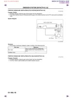
BODY CONTROL SYSTEM : Component Parts Location
INFOID:0000000011101644
RHD models
C
D
E
F
G
H
I
J
K
L
BCS
JMMIA1869ZZ
N
Behind of instrument lower panel
BCM
O
LHD models
P
Revision: 2014 December
BCS-7
D23
COMPONENT PARTS
[WITH INTELLIGENT KEY SYSTEM]
< SYSTEM DESCRIPTION >
JMMIA1980ZZ
Behind of instrument lower panel
BCM
POWER CONSUMPTION CONTROL SYSTEM
POWER CONSUMPTION CONTROL SYSTEM : Component Parts Location
INFOID:0000000011101645
RHD models
Revision: 2014 December
BCS-8
D23
COMPONENT PARTS
[WITH INTELLIGENT KEY SYSTEM]
< SYSTEM DESCRIPTION >
A
B
C
D
E
F
G
H
I
J
K
JMMIA1870ZZ
Combination meter
BCM
Refer to BCS-7, "BODY CONTROL
SYSTEM : Component Parts Location".
IPDM E/R
Refer to PCS-6, "Component Parts
Location".
L
Transfer control unit
Refer to DLN-11, "Component Parts
Location".
BCS
LHD models
N
O
P
Revision: 2014 December
BCS-9
D23
COMPONENT PARTS
[WITH INTELLIGENT KEY SYSTEM]
< SYSTEM DESCRIPTION >
JMMIA1981ZZ
Combination meter
Transfer control unit
Refer to DLN-11, "Component Parts
Location".
IPDM E/R
Refer to PCS-6, "Component Parts
Location".
BCM
Refer to BCS-7, "BODY CONTROL
SYSTEM : Component Parts Location".
Revision: 2014 December
BCS-10
D23
SYSTEM
[WITH INTELLIGENT KEY SYSTEM]
< SYSTEM DESCRIPTION >
SYSTEM
A
BODY CONTROL SYSTEM
BODY CONTROL SYSTEM : System Description
INFOID:0000000011101646
B
OUTLINE
• BCM (Body Control Module) controls the various electrical components. It inputs the information required to
the control from CAN communication and the signal received from each switch and sensor.
• BCM has combination switch reading function for reading the operation status of combination switches (light,
turn signal, wiper and washer) in addition to a function for controlling the operation of various electrical components. It also has the signal transmission function as the passed point of signal and the power saving control function that reduces the power consumption with the ignition switch OFF.
• BCM is equipped with the diagnosis function that performs the diagnosis with CONSULT and various settings.
BCM CONTROL FUNCTION LIST
System
Reference
Combination switch reading system
Signal buffer system
BCS-17, "SIGNAL BUFFER SYSTEM : System Description"
Power consumption control system
BCS-18, "POWER CONSUMPTION CONTROL SYSTEM : System Description"
Headlamp system
• EXL-21, "HEADLAMP SYSTEM : System Description" (LED
type headlamp)
• EXL-240, "HEADLAMP SYSTEM : System Description" (Halogen type headlamp)
Auto light system
EXL-24, "AUTO LIGHT SYSTEM : System Description"
Turn signal and hazard warning lamp system
• EXL-29, "TURN SIGNAL AND HAZARD WARNING LAMP
SYSTEM : System Description" (LED type headlamp)
• EXL-246, "TURN SIGNAL AND HAZARD WARNING LAMP
SYSTEM : System Description" (Halogen type headlamp)
Parking, license plate and tail lamps system
• EXL-31, "PARKING, LICENSE PLATE AND TAIL LAMP SYSTEM : System Description" (LED type headlamp)
• EXL-248, "PARKING, LICENSE PLATE AND TAIL LAMP SYSTEM : System Description" (Halogen type headlamp)
Front fog lamp system
• EXL-35, "FRONT FOG LAMP SYSTEM : System Description"
(LED type headlamp)
• EXL-252, "FRONT FOG LAMP SYSTEM : System Description" (Halogen type headlamp)
Exterior lamp battery saver system
• EXL-37, "EXTERIOR LAMP BATTERY SAVER SYSTEM :
System Description" (LED type headlamp)
• EXL-254, "EXTERIOR LAMP BATTERY SAVER SYSTEM :
System Description" (Halogen type headlamp)
Interior room lamp control system
INL-13, "INTERIOR ROOM LAMP CONTROL SYSTEM : System
Description"
Interior room lamp battery saver system
INL-17, "INTERIOR ROOM LAMP BATTERY SAVER SYSTEM :
System Description"
Illumination control system
INL-20, "ILLUMINATION CONTROL SYSTEM : System Description"
Front wiper and washer system
WW-11, "FRONT WIPER AND WASHER SYSTEM : System Description"
Rear window defogger system
• DEF-9, "WITH AUTO A/C : System Description" (With auto A/
C)
• DEF-10, "WITH MANUAL A/C : System Description" (Without
auto A/C)
Warning chime system
WCS-9, "WARNING CHIME SYSTEM : System Description"
BCS-11
D
E
F
BCS-13, "COMBINATION SWITCH READING SYSTEM : System Description"
Revision: 2014 December
C
G
H
I
D23
J
K
L
BCS
N
O
P
SYSTEM
[WITH INTELLIGENT KEY SYSTEM]
< SYSTEM DESCRIPTION >
System
Reference
Automatic air conditioning control system
HAC-21, "AUTOMATIC AIR CONDITIONING SYSTEM : System
Description"
Manual air conditioning control system
HAC-136, "System Description"
Power door lock system
DLK-22, "System Description"
Intelligent Key system
DLK-25, "INTELLIGENT KEY SYSTEM : System Description"
Engine start system
SEC-18, "INTELLIGENT KEY SYSTEM/ENGINE START FUNCTION : System Description"
Nissan Anti-Theft System (NATS)
SEC-24, "NISSAN ANTI-THEFT SYSTEM : System Description"
Vehicle security system
SEC-30, "VEHICLE SECURITY SYSTEM : System Description"
BODY CONTROL SYSTEM : Fail-safe
INFOID:0000000011190229
FAIL-SAFE CONTROL BY DTC
BCM performs fail-safe control when any DTC are detected.
Display contents of CONSULT
Fail-safe
B2013: ID DISCORD BCM-S/L
Inhibit engine cranking
B2014: CHAIN OF S/L-BCM
Inhibit engine cranking
B2192: ID DISCORD BCM-ECM
Inhibit engine cranking
B2193: CHAIN OF BCM-ECM
Inhibit engine cranking
B2195: ANTI-SCANNING
Inhibit engine cranking
B2198: NATS ANTENNA AMP
Inhibit engine cranking
B2557: VEHICLE SPEED
Inhibit steering lock
B2560: STARTER CONT RELAY
Inhibit engine cranking
B2601: SHIFT POSITION
Inhibit steering lock
B2602: SHIFT POSITION
Inhibit steering lock
B2603: SHIFT POSI STATUS
Inhibit steering lock
B2604: PNP/CLUTCH SW
Inhibit steering lock
B2605: PNP/CLUTCH SW
Inhibit steering lock
B2608: STARTER RELAY
Inhibit engine cranking
B2609: S/L STATUS
• Inhibit engine cranking
• Inhibit steering lock
B260B: STEERING LOCK UNIT
Inhibit steering lock
B260D: STEERING LOCK UNIT
Inhibit steering lock
B260F: ENG STATE SIG LOST
Inhibit engine cranking
B2612: S/L STATUS
• Inhibit engine cranking
• Inhibit steering lock
B2617: BCM
Inhibit engine cranking
B2619: BCM
Inhibit engine cranking
B261F: ASCD CNCL/CLTCH SW
Inhibit steering lock
B2620: NEUTRAL SW
Inhibit steering lock
B26E8: CLUTCH SW
Inhibit steering lock
B26EF: STRG LCK RELAY OFF
Inhibit engine cranking
B26F0: STRG LCK RELAY ON
Inhibit engine cranking
B26F1: IGN RELAY OFF
Inhibit engine cranking
B26F2: IGN RELAY ON
Inhibit engine cranking
B26F3: START CONT RLY ON
Inhibit engine cranking
Revision: 2014 December
BCS-12
D23
SYSTEM
[WITH INTELLIGENT KEY SYSTEM]
< SYSTEM DESCRIPTION >
Display contents of CONSULT
Fail-safe
A
B26F4: START CONT RLY OFF
Inhibit engine cranking
B26F7: BCM
Inhibit engine cranking by Intelligent Key system
U0415: VEHICLE SPEED
Inhibit steering lock
B
FAIL-SAFE CONTROL OF COMBINATION SWITCH READING FUNCTION CAUSED BY LOW
POWER SUPPLY VOLTAGE
If voltage of battery power supply lower, BCM maintains combination switch reading to the status when input
voltage is less than approximately 9 V.
NOTE:
When voltage of battery power supply is approximately 9 V or more, combination switch reading function
returns to normal operation.
C
D
COMBINATION SWITCH READING SYSTEM
COMBINATION SWITCH READING SYSTEM : System Description
E
INFOID:0000000011101648
SYSTEM DIAGRAM
F
G
H
I
J
K
JMMIA1871GB
NOTE:
*: TAIL LAMP switch links lighting switch 1ST and 2ND positions.
L
OUTLINE
• BCM reads the status of the combination switch (light, turn signal, wiper and washer) and recognizes the
status of each switch.
• BCM has a combination of 5 output terminals (OUTPUT 1 - 5) and 5 input terminals (INPUT 1 - 5). It reads a BCS
maximum of 20 switch status.
COMBINATION SWITCH MATRIX
N
O
P
Revision: 2014 December
BCS-13
D23
SYSTEM
[WITH INTELLIGENT KEY SYSTEM]
< SYSTEM DESCRIPTION >
Combination switch circuit
JMMIA0423GB
NOTE:
*: TAIL LAMP switch links lighting switch 1ST and 2ND positions.
Combination switch INPUT-OUTPUT system list
System
INPUT 1
INPUT 2
INPUT 3
INPUT 4
INPUT 5
OUTPUT 1
—
FR WASHER
FR WIPER LOW
TURN LH
TURN RH
OUTPUT 2
FR WIPER HI
—
FR WIPER INT
PASSING
HEADLAMP 1
OUTPUT 3
WIP VOLUME 1
—
—
HEADLAMP 2
HI BEAM
OUTPUT 4
—
WIP VOLUME 3
AUTO LIGHT
—
TAIL LAMP
OUTPUT 5
WIP VOLUME 2
—
—
FR FOG
—
NOTE:
Headlamp has a dual system switch.
COMBINATION SWITCH READING FUNCTION
Description
• BCM reads the status of the combination switch at 10 ms interval normally.
JPMIA0609GB
NOTE:
BCM reads the status of the combination switch at 60 ms interval when BCM is controlled at low power consumption control mode.
• BCM operates as follows and judges the status of the combination switch.
- It operates the transistor on OUTPUT side in the following order: OUTPUT 1 → 2 → 3 → 4 → 5, and outputs
voltage waveform.
- The voltage waveform of OUTPUT corresponding to the formed circuit is input into the interface on INPUT
side if any (1 or more) switches are ON.
Revision: 2014 December
BCS-14
D23
SYSTEM
[WITH INTELLIGENT KEY SYSTEM]
< SYSTEM DESCRIPTION >
- It reads this change of the voltage as the status signal of the combination switch.
A
B
C
D
E
F
JMMIA0326GB
Operation Example
In the following operation example, the combination of the status signals of the combination switch is replaced
as follows: INPUT 1 - 5 to “1 - 5” and OUTPUT 1 - 5 to “A - E”.
G
Example 1: When a switch (TAIL LAMP switch) is turned ON
• The circuit between OUTPUT 4 and INPUT 5 is formed when the TAIL LAMP switch is turned ON.
H
I
J
K
L
BCS
JMMIA0424GB
• BCM detects the combination switch status signal “5D” when the signal of OUTPUT 4 is input to INPUT 5.
• BCM judges that the TAIL LAMP switch is ON when the signal “5D” is detected.
N
Example 2: When some switches (TURN RH switch, TAIL LAMP switch) are turned ON
O
P
Revision: 2014 December
BCS-15
D23
SYSTEM
[WITH INTELLIGENT KEY SYSTEM]
< SYSTEM DESCRIPTION >
• The circuits between OUTPUT 1 and INPUT 5 and between OUTPUT 4 and INPUT 5 are formed when the
TURN RH switch and TAIL LAMP switch are turned ON.
JMMIA0425GB
• BCM detects the combination switch status signal “5AD” when the signals of OUTPUT 1 and OUTPUT 4 are
input to INPUT 5.
• BCM judges that the TURN RH switch and TAIL LAMP switch are ON when the signal “5AD” is detected.
WIPER INTERMITTENT DIAL POSITION
BCM judges the wiper volume dial 1 - 7 by the status of WIP VOLUME 1, 2 and 3 switches.
Wiper volume dial position
Switch status
WIP VOLUME 1
WIP VOLUME 2
WIP VOLUME 3
1
ON
ON
ON
2
ON
ON
OFF
3
ON
OFF
OFF
4
OFF
OFF
OFF
5
OFF
OFF
ON
6
OFF
ON
ON
7
OFF
ON
OFF
NOTE:
For details of wiper volume dial position, refer to WW-11, "FRONT WIPER AND WASHER SYSTEM : System
Description".
SIGNAL BUFFER SYSTEM
Revision: 2014 December
BCS-16
D23
SYSTEM
[WITH INTELLIGENT KEY SYSTEM]
< SYSTEM DESCRIPTION >
SIGNAL BUFFER SYSTEM : System Description
INFOID:0000000011101649
A
SYSTEM DIAGRAM
B
C
D
E
F
G
H
JMMIA1872GB
I
OUTLINE
BCM has the signal transmission function that outputs/transmits each input/received signal to each unit.
J
Signal transmission function list
Signal name
Stop lamp switch signal
Door switch signal
Input
Output
Stop lamp switch
Any door switch
Description
• TCM (CAN)
• Transfer control unit (CAN)
Inputs the stop lamp switch 1
signal and stop lamp switch 2
signal, and transmits it via CAN
communication.
• Combination meter (CAN)
• IPDM E/R (CAN)
Inputs the door switch signal
and transmits it via CAN communication.
Ignition switch ON signal
Push-button ignition switch
(Push switch)
IPDM E/R (CAN)
Inputs the push-button ignition
switch (push switch) signal and
transmits the ignition switch status judged with BCM via CAN
communication.
A/C ON signal
• A/C auto amp. (Auto A/C)
• A/C amp. (Manual A/C)
ECM (CAN)
Input A/C ON signal, and transmits it via CAN communication.
K
L
BCS
N
O
P
Revision: 2014 December
BCS-17
D23
SYSTEM
[WITH INTELLIGENT KEY SYSTEM]
< SYSTEM DESCRIPTION >
Signal name
Blower fan ON signal
Interlock/PNP switch signal
Input
Output
• A/C auto amp. (Auto A/C)
• A/C amp. (Manual A/C)
• Transmission range switch
(A/T models)
• Clutch interlock switch (M/T
models)
Description
ECM (CAN)
Input blower fan ON signal, and
transmits it via CAN communication.
IPDM E/R (CAN)
• Inputs the P/N position signal,
and transmits the interlock/
PNP switch signal via CAN
communication. (A/T models)
• Inputs the clutch interlock
switch signal, and transmits
the interlock/PNP switch signal via CAN communication.
(M/T models)
POWER CONSUMPTION CONTROL SYSTEM
POWER CONSUMPTION CONTROL SYSTEM : System Description
INFOID:0000000011101650
SYSTEM DIAGRAM
JMMIA1873GB
OUTLINE
• BCM incorporates a power saving control function that reduces the power consumption according to the
vehicle status.
• BCM switches the status (control mode) by itself with the power saving control function. It performs the sleep
request to each unit (IPDM E/R, combination meter and transfer control unit) that operates with the ignition
switch OFF.
Normal mode (wake-up)
- CAN communication is normally performed with other units
- Each control with BCM is operating properly
CAN communication sleep mode (CAN sleep)
- CAN transmission is stopped
- Control with BCM only is operating
Low power consumption mode (BCM sleep)
- Low power consumption control is active
- CAN transmission is stopped
LOW POWER CONSUMPTION CONTROL WITH BCM
BCM reduces the power consumption with the following operation in the low power consumption mode.
• The reading interval of the each switches changes from 10 ms interval to 60 ms interval.
Sleep mode activation
• BCM receives the sleep-ready signal (ready) from IPDM E/R, combination meter and transfer control unit via
CAN communication.
Revision: 2014 December
BCS-18
D23
SYSTEM
[WITH INTELLIGENT KEY SYSTEM]
< SYSTEM DESCRIPTION >
• BCM transmits the sleep wake up signal (sleep) to each unit when all of the CAN sleep conditions are fulfilled.
• Each unit stops the transmission of CAN communication with the sleep wake up signal. BCM is in CAN communication sleep mode.
• BCM is in the low power consumption mode and perform the low power consumption control when all of the
BCM sleep conditions are fulfilled with CAN sleep condition.
A
B
Sleep condition
CAN sleep condition
•
•
•
•
•
•
•
•
•
•
•
•
•
Receiving the sleep-ready signal (ready) from all units
1 minute after turning ignition switch OFF
Theft warning alarm: Not operation
Warning chime: Not operation
Intelligent Key system buzzer: Not operation
Stop lamp switch: OFF
Turn signal indicator lamp: Not operation
Exterior lamp: OFF
Door lock status: No change
CONSULT communication status: Not communication
Meter display signal: Non-transmission
Door switch status: No change
Rear window defogger: OFF
BCM sleep condition
C
D
• Interior room lamp battery saver: Time out*
• Nissan Anti-Theft System (NATS): Not operation
• Remote keyless entry receiver communication status: No communication
• ACC/ON indicator lamp: Not operation
E
F
NOTE:
*: Refer to INL-17, "INTERIOR ROOM LAMP BATTERY SAVER SYSTEM : System Description" for details of
the interior room lamp battery saver time.
Wake-up operation
• BCM transmits sleep wake up signal (wake up) to each unit when any condition listed below is established,
and then goes into normal mode from low power consumption mode.
• Each unit starts transmissions with CAN communication by receiving sleep wake up signals. Each unit transmit wake up signals to BCM with CAN communication to convey the start of CAN communication.
G
H
I
Wake-up condition
Wake-up condition
•
•
•
•
•
•
•
•
•
•
•
•
•
•
•
•
•
•
•
•
•
•
J
Receiving the sleep-ready signal (Not-ready) from any units
Push-button ignition switch (push switch): OFF→ ON
Hazard switch: ON
HI BEAM switch: OFF → ON, ON → OFF
PASSING switch: OFF → ON, ON → OFF
HEADLAMP 1 switch: OFF → ON, ON → OFF
HEADLAMP 2 switch: OFF → ON, ON → OFF
TAIL LAMP switch: OFF → ON
FR FOG switch: OFF → ON, ON → OFF
TURN RH switch: OFF → ON
TURN LH switch: OFF → ON
Driver door switch: OFF → ON, ON → OFF
Passenger door switch: OFF → ON, ON → OFF
Rear RH door switch: OFF → ON, ON → OFF
Rear LH door switch: OFF → ON, ON → OFF
Driver door request switch: OFF → ON
Passenger door request switch: OFF → ON
Stop lamp switch: ON
Door lock and unlock switch: NEUTRAL → LOCK, NEUTRAL → UNLOCK
Remote keyless entry receiver communication: Receiving
Front door lock assembly (driver side) (unlock sensor): OFF → ON, ON → OFF
Clutch interlock switch: OFF → ON
K
L
BCS
N
O
P
Revision: 2014 December
BCS-19
D23
DIAGNOSIS SYSTEM (BCM)
[WITH INTELLIGENT KEY SYSTEM]
< SYSTEM DESCRIPTION >
DIAGNOSIS SYSTEM (BCM)
COMMON ITEM
COMMON ITEM : CONSULT Function (BCM - COMMON ITEM) (With Intelligent Key)
INFOID:0000000011101651
APPLICATION ITEM
CONSULT performs the following functions via CAN communication with BCM.
Diagnosis mode
Function Description
Work Support
Changes the setting for each system function.
Self Diagnostic Result
Displays the diagnosis results judged by BCM.
CAN Diag Support Monitor
Monitors the reception status of CAN communication viewed from BCM.
Data Monitor
The BCM input/output signals are displayed.
Active Test
The signals used to activate each device are forcibly supplied from BCM.
Ecu Identification
The BCM part number is displayed.
Configuration
• Read and save the vehicle specification.
• Write the vehicle specification when replacing BCM.
SYSTEM APPLICATION
BCM can perform the following functions for each system.
NOTE:
It can perform the diagnosis modes except the following for all sub system selection items.
×: Applicable item
System
Sub system selection item
Diagnosis mode
Work Support
Data Monitor
Active Test
Door lock
DOOR LOCK
×
×
Rear window defogger
REAR DEFOGGER
×
×
Warning chime
BUZZER
×
×
Interior room lamp timer
INT LAMP
ì
ì
ì
Exterior lamp
HEAD LAMP
ì
ì
ì
Wiper and washer
WIPER
ì
ì
ì
Turn signal and hazard warning lamps
FLASHER
ì
ì
ì
ã Automatic A/C
• Manual A/C
AIR CONDITONER
• Intelligent Key system
• Engine start system
INTELLIGENT KEY
Combination switch
COMB SW
Body control system
BCM
NATS
IMMU
Interior room lamp battery saver
—
Theft warning alarm
×
×
×
×
×
×
×
BATTERY SAVER
×
×
×
×
×
TRUNK*
×
THEFT ALM
×
—
RETAINED PWR*
×
Signal buffer system
SIGNAL BUFFER
×
×
×
NOTE:
*: This item is displayed, but not used.
FREEZE FRAME DATA (FFD)
The BCM records the following vehicle condition at the time a particular DTC is detected, and displays on
CONSULT.
Revision: 2014 December
BCS-20
D23
DIAGNOSIS SYSTEM (BCM)
[WITH INTELLIGENT KEY SYSTEM]
< SYSTEM DESCRIPTION >
CONSULT screen item
Indication/Unit
Description
A
Vehicle Speed
km/h
Vehicle speed of the moment a particular DTC is detected
Odo/Trip Meter
km
Total mileage (Odometer value) of the moment a particular DTC is detected
SLEEP>LOCK
While turning BCM status from low power consumption mode to
normal mode (Power supply position is “LOCK”)
SLEEP>OFF
While turning BCM status from low power consumption mode to
normal mode (Power supply position is “OFF”.)
LOCK>ACC
While turning power supply position from “LOCK” to “ACC”
ACC>ON
While turning power supply position from “ACC” to “IGN”
RUN>ACC
While turning power supply position from “RUN” to “ACC” (Vehicle
is stopping and selector lever is except P position.)
CRANK>RUN
While turning power supply position from “CRANKING” to “RUN”
(From cranking up the engine to run it)
RUN>URGENT
While turning power supply position from “RUN“ to “ACC” (Emergency stop operation)
ACC>OFF
Vehicle Condition
OFF>LOCK
OFF>ACC
IGN Counter
Power supply position
status of the moment a
particular DTC is detected*
E
F
While turning power supply position from “ACC” to “OFF”
While turning power supply position from “OFF” to “LOCK”
While turning power supply position from “OFF” to “ACC”
G
While turning power supply position from “IGN” to “CRANKING”
OFF>SLEEP
While turning BCM status from normal mode (Power supply position is “OFF”.) to low power consumption mode
LOCK>SLEEP
While turning BCM status from normal mode (Power supply position is “LOCK”.) to low power consumption mode
LOCK
Power supply position is “LOCK”.
OFF
Power supply position is “OFF”.
ACC
Power supply position is “ACC”.
ON
Power supply position is “IGN”
ENGINE RUN
Power supply position is “RUN”.
CRANKING
Power supply position is “CRANKING”.
J
K
The number of times that ignition switch is turned ON after DTC is detected
• The number is 0 when a malfunction is detected now.
• The number increases like 1 → 2 → 3...38 → 39 after returning to the normal condition
whenever ignition switch OFF → ON.
• The number is fixed to 39 until the self-diagnosis results are erased if it is over 39.
N
O
INFOID:0000000011370720
BCM CONSULT FUNCTION
CONSULT performs the following functions via CAN communication with BCM.
DATA MONITOR
NOTE:
The following table includes information (items) inapplicable to this vehicle. For information (items) applicable
to this vehicle, refer to CONSULT display items.
BCS-21
L
BCS
DOOR LOCK
DOOR LOCK : CONSULT Function (BCM - DOOR LOCK)
H
I
NOTE:
*: Refer to the following for details at the power supply position.
• LOCK: Ignition switch OFF with steering locked
• OFF: Ignition switch OFF with steering unlocked
• ACC: Ignition switch ACC
• IGN: Ignition switch ON with engine stopped
• RUN: Ignition switch ON with engine running
• CRANKING: At engine cranking
Revision: 2014 December
C
D
ON>CRANK
0 - 39
B
D23
P
DIAGNOSIS SYSTEM (BCM)
[WITH INTELLIGENT KEY SYSTEM]
< SYSTEM DESCRIPTION >
Monitor Item
Contents
REQ SW-DR
Indicated [On/Off] condition of front door request switch (driver side)
REQ SW-AS
Indicated [On/Off] condition of front door request switch (passenger side)
REQ SW-BD/TR
NOTE:
This item is displayed, but cannot be monitored
DOOR SW-DR
Indicated [On/Off] condition of front door switch (driver side)
DOOR SW-AS
Indicated [On/Off] condition of front door switch (passenger side)
DOOR SW-RR
Indicated [On/Off] condition of rear door switch RH
NOTE:
For king cab models: this item is displayed, but cannot be monitored
DOOR SW-RL
Indicated [On/Off] condition of rear door switch LH
NOTE:
For king cab models: this item is displayed, but cannot be monitored
DOOR SW-BK
NOTE:
This item is displayed, but cannot be monitored
CDL LOCK SW
Indicated [On/Off] condition of lock signal from door lock and unlock switch
CDL UNLOCK SW
Indicated [On/Off] condition of unlock signal from door lock and unlock switch
KEY CYL LK-SW
NOTE:
This item is displayed, but cannot be monitored
KEY CYL UN-SW
NOTE:
This item is displayed, but cannot be monitored
ACTIVE TEST
Test item
Description
DOOR LOCK
This test is able to check door lock/unlock operation
• ALL LOCK: The all door lock actuators are locked
• DR UNLK: This item is displayed, but cannot be used
• OTR ULK: This item is displayed, but cannot be used
• ALL UNLK: The all door lock actuators are unlocked
• BD ULK: This item is displayed, but cannot be used
SUPER LOCK
NOTE:
This item is displayed, but cannot be used
DOOR LOCK IND
NOTE:
This item is displayed, but cannot be monitored
REAR WINDOW DEFOGGER
REAR WINDOW DEFOGGER : CONSULT Function (BCM - REAR DEFOGGER)
INFOID:0000000011370730
DATA MONITOR
NOTE:
The following table includes information (items) inapplicable to this vehicle. For information (items) applicable
to this vehicle, refer to CONSULT display items.
Monitor Item
Description
REAR DEF SW
Displays “Press (ON)/other (OFF)” status determined with the rear window defogger switch.
PUSH SW
Indicates [ON/OFF] condition of push switch.
ACTIVE TEST
Test Item
REAR DEFOGGER
Revision: 2014 December
Description
Rear window defogger operates when “ON” on CONSULT screen is touched.
BCS-22
D23
DIAGNOSIS SYSTEM (BCM)
[WITH INTELLIGENT KEY SYSTEM]
< SYSTEM DESCRIPTION >
BUZZER
A
BUZZER : CONSULT Function (BCM - BUZZER)
INFOID:0000000011370732
DATA MONITOR
B
NOTE:
The following table includes information (items) inapplicable to this vehicle. For information (items) applicable
to this vehicle, refer to CONSULT display items.
C
Display item
[Unit]
Description
D
PUSH SW
[On/Off]
Status of push-button ignition switch judged by BCM.
UNLK SEN-DR
[On/Off]
Status of unlock sensor judged by BCM.
VEH SPEED 1
[km/h]
Value of vehicle speed signal received from combination meter with CAN communication line.
TAIL LAMP SW
[On/Off]
Status of lighting switch judged by BCM using the combination switch readout function.
FR FOG SW
[On/Off]
Status of front fog lamp switch judged by BCM using the combination switch readout function.
DOOR SW-DR
[On/Off]
Status of driver side door switch judged by BCM.
CDL LOCK SW
[On/Off]
Status of door lock unlock switch judged by BCM.
E
F
G
H
ACTIVE TEST
I
Display item
[Unit]
LIGHT WARN ALM
Description
J
The light warning chime operation can be checked by operating the relevant function (On/Off).
NOTE:
Some items are not available according to vehicle specification.
K
INT LAMP
INT LAMP : CONSULT Function (BCM - INT LAMP)
INFOID:0000000011370727
L
WORK SUPPORT
Service item
SET I/L D-UNLCK INTCON
ROOM LAMP TIMER SET
ROOM LAMP ON TIME SET
Revision: 2014 December
Setting item
BCS
Setting
On*1
With the interior room lamp timer function
Off
Without the interior room lamp timer function
MODE 2
7.5 sec.
MODE 3*1
15 sec.
MODE 4
30 sec.
MODE 1
0.5 sec.
MODE 2*1
1 sec.
MODE 3
2 sec.
MODE 4
3 sec.
MODE 5
4 sec.
MODE 6
5 sec.
MODE 7
0 sec.
N
Sets the interior room lamp ON time. (Timer operating time)
O
P
Sets the interior room lamp gradual brightening time.
BCS-23
D23
DIAGNOSIS SYSTEM (BCM)
[WITH INTELLIGENT KEY SYSTEM]
< SYSTEM DESCRIPTION >
Service item
ROOM LAMP OFF TIME SET
Setting item
MODE 1
0.5 sec.
MODE 2*1
1 sec.
MODE 3
2 sec.
MODE 4
3 sec.
MODE 5
4 sec.
MODE 6
5 sec.
MODE 7
MODE 1*
R LAMP TIMER LOGIC SET
FOG LAMP OVERRIDE*2
Setting
Sets the interior room lamp gradual dimming time.
0 sec.
1
Interior room lamp timer activates with synchronizing all doors.
MODE 2
Interior room lamp timer activates with synchronizing the driver door
only.
On
With front fog override function
Off*1
Without front fog override function
*1: Factory setting
*2: For models without auto light system, this item is displayed but can not be used
DATA MONITOR
NOTE:
The following table includes information (items) inapplicable to this vehicle. For information (items) applicable
to this vehicle, refer to CONSULT display items.
Monitor item
[Unit]
Description
REQ SW -DR
[On/Off]
Indicated [On/Off] condition of door request switch (driver side)
REQ SW -AS
[On/Off]
Indicated [On/Off] condition of door request switch (passenger side)
REQ SW -RR
[On/Off]
NOTE:
The item is indicated, but not monitored.
REQ SW -RL
[On/Off]
NOTE:
The item is indicated, but not monitored.
PUSH SW
[On/Off]
Indicates [On/Off] condition of push-button ignition switch
UNLK SEN -DR
[On/Off]
Indicates [On/Off] condition of driver door UNLOCK status
DOOR SW-DR
[On/Off]
Indicated [On/Off] condition of front door switch (driver side)
DOOR SW-AS
[On/Off]
Indicated [On/Off] condition of front door switch (passenger side)
DOOR SW-RR
[On/Off]
Indicated [On/Off] condition of rear door switch RH*
DOOR SW-RL
[On/Off]
Indicated [On/Off] condition of rear door switch LH*
DOOR SW-BK
[On/Off]
NOTE:
The item is indicated, but not monitored
CDL LOCK SW
[On/Off]
Indicated [On/Off] condition of lock signal from door lock unlock switch
CDL UNLOCK SW
[On/Off]
Indicated [On/Off] condition of unlock signal from door lock unlock switch
KEY CYL LK-SW
[On/Off]
NOTE:
The item is indicated, but not monitored
Revision: 2014 December
BCS-24
D23
DIAGNOSIS SYSTEM (BCM)
[WITH INTELLIGENT KEY SYSTEM]
< SYSTEM DESCRIPTION >
Monitor item
[Unit]
Description
KEY CYL UN-SW
[On/Off]
NOTE:
The item is indicated, but not monitored
TRNK/HAT MNTR
[On/Off]
NOTE:
The item is indicated, but not monitored
RKE-LOCK
[On/Off]
Indicates [On/Off] condition of LOCK signal from Intelligent Key
RKE-UNLOCK
[On/Off]
Indicates [On/Off] condition of UNLOCK signal from Intelligent Key
A
B
C
D
*: For king cab models: this item is displayed, but cannot be monitored
ACTIVE TEST
Test item
Operation
INT LAMP
E
Description
On
Outputs the interior room lamp control signal.
Off
Stops the interior room lamp control signal.
F
HEADLAMP
HEADLAMP : CONSULT Function (BCM - HEAD LAMP) (LED Headlamp)
INFOID:0000000011370725
G
WORK SUPPORT
H
Service item
Setting item
MODE1*2
CUSTOM A/LIGHT SETTING*1
BATTERY SAVER SET
HEAD LIGHT TIMER*
AUTO LIGHT LOGIC SET*1
Normal
MODE2
More sensitive setting than normal setting (Turns ON earlier than normal operation)
MODE3
More sensitive setting than MODE2 (Turns ON earlier than MODE2)
MODE4
Less sensitive setting than normal setting (Turns ON later than normal operation)
On*2
Off
1
Setting
MODE1
I
J
With the exterior lamp battery saver function
Without the exterior lamp battery saver function
K
10 sec.
Sets follow me home function activating time
MODE2*2
30 sec.
MODE1*2
With twilight ON custom & with wiper INT, LO and HI
MODE2
With twilight ON custom & with wiper LO and HI
MODE3
With twilight ON custom & without
MODE4
Without twilight ON custom & with wiper INT, LO and HI
MODE5
Without twilight ON custom & with wiper LO and HI
MODE6
Without twilight ON custom & without
L
BCS
N
1
* : Without auto light system, this item cannot be used.
*2: Factory setting
O
DATA MONITOR
NOTE:
The following table includes information (items) inapplicable to this vehicle. For information (items) applicable
to this vehicle, refer to CONSULT display items.
Revision: 2014 December
BCS-25
D23
P